EP2202864A2 - Chargeur pour dispositif électronique, dispositif électronique et procédé de chargement - Google Patents
Chargeur pour dispositif électronique, dispositif électronique et procédé de chargement Download PDFInfo
- Publication number
- EP2202864A2 EP2202864A2 EP09180106A EP09180106A EP2202864A2 EP 2202864 A2 EP2202864 A2 EP 2202864A2 EP 09180106 A EP09180106 A EP 09180106A EP 09180106 A EP09180106 A EP 09180106A EP 2202864 A2 EP2202864 A2 EP 2202864A2
- Authority
- EP
- European Patent Office
- Prior art keywords
- charging
- electronic device
- power supply
- current value
- unit
- Prior art date
- Legal status (The legal status is an assumption and is not a legal conclusion. Google has not performed a legal analysis and makes no representation as to the accuracy of the status listed.)
- Withdrawn
Links
Images





Classifications
-
- H—ELECTRICITY
- H02—GENERATION; CONVERSION OR DISTRIBUTION OF ELECTRIC POWER
- H02J—ELECTRIC POWER NETWORKS; CIRCUIT ARRANGEMENTS OR SYSTEMS FOR SUPPLYING OR DISTRIBUTING ELECTRIC POWER; SYSTEMS FOR STORING ELECTRIC ENERGY
- H02J7/00—Circuit arrangements for charging or discharging batteries or for supplying loads from batteries
- H02J7/34—Parallel operation in networks using both storage and other DC sources, e.g. providing buffering
- H02J7/342—The other DC source being a battery actively interacting with the first one, i.e. battery to battery charging
-
- H—ELECTRICITY
- H02—GENERATION; CONVERSION OR DISTRIBUTION OF ELECTRIC POWER
- H02J—ELECTRIC POWER NETWORKS; CIRCUIT ARRANGEMENTS OR SYSTEMS FOR SUPPLYING OR DISTRIBUTING ELECTRIC POWER; SYSTEMS FOR STORING ELECTRIC ENERGY
- H02J7/00—Circuit arrangements for charging or discharging batteries or for supplying loads from batteries
Definitions
- Japanese Laid-Open Patent Publication No. 2006-243863 describes technology for sending input current of bus power, which is obtained from a USB bus, to a power supply line of an HDD block.
- a charging circuit uses some of the input current to charge a rechargeable battery.
- a step-up circuit increases the output voltage of the rechargeable battery, and the output current of the rechargeable battery is added to the current of the power supply line and supplied to the HDD block. This ensures that the HDD block is supplied with sufficient drive power while the value of the current flowing to the USB remain in accordance with the standardized specification.
- USB standard allows for two different currents to be supplied, 100 mA and 500 mA.
- An AC adapter incorporating a USB connector may be used to charge a USB-applicable electronic device.
- the AC adapter serves as the connection origin.
- the electronic device cannot perform USB communication and therefore cannot determine the specified current of the AC adapter.
- One embodiment of the present invention is a charger for an electronic device that charges a rechargeable battery arranged in the electronic device.
- the charger includes a detection unit which detects connection of another electronic device to the electronic device through a communication cable including a power supply line.
- a charging unit charges the rechargeable battery with power supply voltage from the power supply line of the communication cable.
- a measurement unit acquires a measurement value indicating a degree of a voltage drop of the power supply voltage occurred when the charging unit performs charging.
- a control unit instructs a charging current value for charging the rechargeable battery with the charging unit.
- the control unit monitors the measurement value obtained by the measurement unit while instructing the charging unit to increase the charging current value from an initial current value and determines the charging current value based on the monitored measurement value.
- a further embodiment of the present invention is an electronic device capable of using a rechargeable battery.
- the electronic device includes a charger which charges the rechargeable battery that is arranged in the electronic device.
- the charger includes a detection unit which detects connection of another electronic device to the electronic device through a communication cable including a power supply line.
- a charging unit charges the rechargeable battery with power supply voltage from the power supply line of the communication cable.
- a measurement unit acquires a measurement value indicating a degree of a voltage drop of the power supply voltage occurred when the charging unit performs charging.
- a control unit instructs a charging current value for charging the rechargeable battery with the charging unit.
- the control unit monitors the measurement value obtained by the measurement unit while instructing the charging unit to increase the charging current value from an initial current value and determines the charging current value based on the monitored measurement value.
- Another embodiment of the present invention is a method for charging a rechargeable battery arranged in an electronic device.
- the method includes detecting, by the electronic device, connection of another electronic device to the electronic device through a communication cable including a power supply line; starting, by the electronic device, charging of the rechargeable battery using a power supply voltage from the power supply line of the communication cable; acquiring, by the electronic device, a measurement value indicating a degree of a voltage drop of the power supply voltage occurred during charging; and determining, by the electronic device, a charging current value of the rechargeable battery based on the measurement value.
- the determining includes monitoring the measurement value during the charging while increasing the charging current value from an initial current value, and updating the charging current value based on the monitored measurement value.
- the electronic device is an electronic still camera 11.
- a release button 16 which a photographer pushes (i.e., activates) when initiating an image capturing operation with the electronic still camera 11, is arranged at the left end on the upper surface of the camera body 12 as viewed in Fig. 1 .
- a monitor such as a liquid crystal display (hereinafter referred to as "LCD 18") is arranged in the rear surface of the camera body 12 (see Fig. 3 ).
- a Universal Serial Bus (USB) connector 20 female connector is arranged in an inner wall surface, which is exposed when a opening a resin terminal cover 19 on one side (left side as viewed in Fig. 1 ) of the camera body 12.
- a USB connector 21 a male connector of a USB cable 21, which serves as a communication cable, is connectable to (insertable into) the USB connector 20.
- the electronic still camera 11 may be USB-connected by the USB cable 21 to another electronic device, which serves as a connection origin.
- the USB cable 21 has one USB connector 21 a, which is connected to the USB connector 20, and another USB connectors 21 b, which is connected to another electronic device.
- Examples of an electronic device that serves as the connection origin includes a personal computer (hereinafter referred to as "PC 22") and an AC adapter 23. It is only required that the other electronic device serving as the connection origin be applicable to USB communication and may be a Personal Digital Assistant (PDA), a mobile phone, a portable game machine, a USB hub, and the like.
- PDA Personal Digital Assistant
- the electronic still camera 11 When detecting a USB connection in a power OFF state (standby mode), the electronic still camera 11 charges a rechargeable battery 41 (shown in Fig. 3 ) with bus power supplied through the USB cable 21.
- the AC adapter 23 includes a plug 24, which is connectable to an outlet for commercial AC power (e.g., AC 100V), converts the AC power to DC power, and outputs direct current with a predetermined voltage (e.g., 5V).
- the AC adapter 23 supplies the direct current with the predetermined voltage (e.g., 5V) to the electronic still camera 11 through the USB cable 21, which is connected to its USB connector (not shown).
- the AC adapter 23 may be a genuine AC adapter 23a, which is sold for exclusive use to supply power to the electronic still camera 11, or a non-genuine AC adapter 23b.
- the standard-specified information of the genuine AC adapter 23a such as the rated current
- the known rated current is a predetermined value in the range of 500 mA to 1000 mA
- the standard-specified information of the non-genuine AC adapter 23b such as the rated current, is not known.
- USB When power supply voltage can be supplied as bus power from an upper level device (e.g.. USB host such as the PC 22 or a PDA) to a lower level device (USB device) through the USB cable 21 with the bus power method, USB is applicable to plug-and-play and also to hot plugging, which allows for connection and disconnection of the USB cable 21 in an active state.
- an upper level device e.g.. USB host such as the PC 22 or a PDA
- USB lower level device
- two currents, 100 mA and 500 mA are specified as the maximum current (specified current) that can be supplied from an electronic device serving as an upper level device (PC 22 etc.) to a lower level device (bus power device).
- the specified current 100 mA or 500 mA
- the power supply voltage (rated voltage) that is suppliable by the genuine AC adapter 23a is set to be outside the USB specified voltage range (4.40 V to 5.25 V in the present example) and greater than or equal to the rated voltage (fully charged voltage) of the rechargeable battery 41 (4.2 V in the present example). In the present example, a voltage exceeding 5.25 V cannot be used.
- the rated voltage of the genuine AC adapter 23a is set to be greater than the rated voltage (4.2 V) of the rechargeable battery 41 and less than the lower limit of the USB specified voltage (4.40 V).
- the rated voltage of the genuine AC adapter 23a is set at "4.3V".
- the electronic still camera 11 includes an engine 35, which performs various types of processing such as image processing.
- the electronic still camera 11 includes a main CPU 25 and a sub-CPU 26.
- the main CPU 25 is arranged in the engine 35 and executes predetermined control programs to centrally control various operations of the electronic still camera 11.
- the sub-CPU 26 serves as a control unit mainly responsible for power supply control.
- the main CPU 25 and the sub-CPU 26 are communicable with each other.
- An operation unit 27 including the above-mentioned release button 16 and the like, a motor control unit 28, a flash control unit 29, a DRAM 31 (frame memory), a flash memory 32 (nonvolatile memory), a memory card 33 (e.g., SD card), the LCD 18, and the USB connector 20 are connected to the main CPU 25.
- the electronic still camera 11 includes a variable optical system, which is formed by an optical lens group including the image capturing lens unit 13 (only the image capturing lens 13 is shown in Fig. 3 ), an aperture, a shutter, and the like.
- the motor control unit 28 performs focusing, aperture adjustment, shutter control, and the like in response to a command from the main CPU 25.
- the main CPU 25 performs a predetermined exposure calculation in response to a photoelectric converted signal from a light measurement element (not shown) to control the shutter and aperture based on the exposure calculation result when the shutter is released.
- the motor control unit 28 includes a lens drive motor, which is driven and controlled by a command from the main CPU 25.
- the motor control unit 28 drives the motor to drive the image capturing lens unit 13 (movable lens) with the motor and change the zoom magnification (focal length) and perform focusing.
- the motor control unit 28 drives an aperture motor to adjust the opening diameter of the aperture to obtain the aperture value that is obtained when the main CPU 25 performs a predetermined exposure calculation using the luminance of the captured subject that is detected from image data.
- the motor control unit 28 drives a shutter motor to drive and control the shutter to obtain an exposure time that is determined through the exposure calculation performed by the main CPU 25.
- the flash control unit 29 performs a light emission control on the flash 14 in accordance with a command from the main CPU 25.
- the main CPU 25 determines the color temperature of the necessary emission light based on color information of the ambient light acquired by the light measurement element. Then, the main CPU 25 transmits a light emission color control signal to the flash control unit 29 so that the flash 14 emits light in correspondence with the determined color temperature.
- the electronic still camera 11 includes an image capturing element 36.
- Light flux from an image-captured subject passes through the variable optical system.
- the image capturing element 36 forms an image from the light of the captured subject at an image side of the image capturing lens unit 13.
- the image capturing element 36 which includes a complementary metal oxide semiconductor (CMOS) image sensor or a charge coupled device (CCD) image sensor, stores signal charges corresponding to the subject image formed on an imaging plane and outputs the accumulated signal charges as an analog signal, which is referred to as a pixel signal.
- CMOS complementary metal oxide semiconductor
- CCD charge coupled device
- the output side of the image capturing element 36 is connected to a signal processing circuit 37.
- the signal processing circuit 37 includes an analog front end (AFE) and an A/D converter.
- the AFE which is controlled by the main CPU 25, performs sampling (correlation double sampling) on the pixel signal, which has undergone photoelectric conversion by the image capturing element 36, at a predetermined timing and amplifies the sampled result to a predetermined signal level based on, for example, ISO sensitivity.
- the A/D converter converts the amplified image signal (analog signal) output from the AFE portion to a digital signal and outputs the digital-converted image data to the engine 35.
- the engine 35 generates a predetermined image signal by performing image processing, such as contour compensation, gamma conversion, white balance processing, and the like, on the digital image signal output from the A/D converter.
- image processing such as contour compensation, gamma conversion, white balance processing, and the like
- the image signal generated by the engine 35 is temporarily stored in the DRAM 31, which functions as a buffer memory.
- the main CPU 25 reads the image data from the DRAM 31, performs JPEG data compression or on the data, and stores the compressed image data in a memory card 33.
- the main CPU 25 reads captured image data from the memory card 33, expands the image data, and stores the image data in the DRAM 31.
- the main CPU 25 also displays an image of the image data on the LCD 18 via an LCD drive circuit (not shown).
- the engine 35 includes a USB controller 39, which is connected to the USB connector 20.
- the USB controller 39 performs a communication complying with the USB communication protocol with the other electronic device, which serves as a connection origin.
- the sub-CPU 26 is supplied with power supply voltage Vbus so that the sub-CPU 26 detects connection of the USB connector 21 a (connection of another electronic device) to the USB connector 20. That is, the sub-CPU 26 detects USB connection when the power of the electronic still camera 11 is off.
- the sub-CPU 26 is connected to the power switch 17 and a power supply circuit 40.
- the power supply circuit 40 is connected to the rechargeable battery 41.
- the sub-CPU 26 controls the power supply circuit 40 based on an operation signal input from the power switch 17 to switch on or off the power of the electronic still camera 11. In a power on state, the power supply circuit 40 is driven by a command from the sub-CPU 26, a plurality of predetermined voltages are generated from the power supply voltage of the rechargeable battery 41, and each section of the electronic still camera 11 is supplied with the necessary power supply voltage.
- the sub-CPU 26 controls the power supply circuit 40 to switch off the power of the electronic still camera 11.
- the power supply circuit 40 stops outputting power supply voltage although it continues to supply voltage to some circuits such as the sub-CPU 26 or a timing counter.
- a lithium-ion battery or the like is used as the rechargeable battery 41.
- Other rechargeable batteries having a rated voltage that can be charged with USB specified voltage may also be used.
- the rechargeable battery 41 is removable from a battery box of the electronic still camera 11 and thus replaceable by the user.
- the rechargeable battery 41 may be fixed in the electronic still camera 11 and irremovable by the user.
- the power supply circuit 40 shown in Fig. 3 includes a charging circuit 42 for charging the rechargeable battery 41.
- the sub-CPU 26 and the power supply circuit 40 form a charger that charges the rechargeable battery 41.
- the sub-CPU 26 includes a flash memory 26a, which stores a charging control process routine illustrated in the flowchart of Fig. 5 . If a USB connection is detected when the power of the electronic still camera 11 is off, the sub-CPU 26 executes the program to perform the charging control on the rechargeable battery 41.
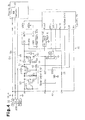
- Fig. 4 is a block diagram showing the engine 35, the sub-CPU 26, and the power supply circuit 40.
- the power supply circuit 40 includes a power supply IC 51, a reset IC 52, a charge control IC 53 serving as a charging unit, a first switch element S1, a second switch element S2, and a third switch element S3.
- the USB controller 39 in the engine 35 is connected to the USB connector 20 by a power supply line 54 of the power supply voltage Vbus, a D+ differential signal line 55, and a D-differential signal line 56.
- the USB cable 21 includes a Vbus power supply line and GND power supply line (both not shown) and a D+ differential signal line and D- differential signal line (both not shown).
- the Vbus power supply line and GND power supply line are respectively connected to a Vbus terminal and a GND terminal of the USB connector 20 when the USB connectors 20 and 21 a are connected.
- the D+ differential signal line and D- differential signal line are respectively connected to the D+ terminal and the D- terminal of the USB connector 20 when the USB connectors 20 and 21a are connected.
- a wire 57 branched from the power supply line 54 is connected to an interruption (INT) terminal of the sub-CPU 26.
- Node A in the wire 57 is connected to the VDD terminal of the power supply IC 51 via the first switch element S1 and a diode D1, which are connected in series.
- the rechargeable battery 41 has a positive electrode connected to the VDD terminal of the power supply IC 51 via the second switch element S2 and a grounded negative electrode.
- the gate terminal G of the second switch element S2 is connected to the anode terminal of the diode D1.
- the diodes in each switch element S1 and S2 are parasitic diodes.
- Node A and the gate terminal G of the third switch element S3 are connected via a resistor R3.
- the gate terminal G of the third switch element S3 is also connected to a Port 2 terminal (open drain) of the sub-CPU 26.
- the gate terminal G of the second switch element S2 is grounded via a resistor R4.
- the first to the third switch elements S1 to S3 are configured by a p-channel MOS field effect transistor (MOSFET).
- the reset IC 52 has an IN terminal connected to the source terminal S of the second switch element S2 and an OUT terminal connected to a Reset terminal of the sub-CPU 26.
- the Port 1 terminal of the sub-CPU 26 is connected to an Enable terminal of the power supply IC 51.
- the sub-CPU 26 opens the Port 2 terminal, which is connected to the gate terminal G of the third switch element S3.
- the first switch element S1 is deactivated and the voltage applied to the gate terminal G of the second switch element S2 has an L level. This deactivates the second switch element S2.
- the sub-CPU 26 determines whether or not the power supply voltage Vbatt of the rechargeable battery 41 input to the IN terminal of the reset IC 52 is greater than or equal to a predetermined voltage. When the power supply voltage Vbatt is greater than or equal to the predetermined voltage, the sub-CPU 26 sends an enable signal from the Port 1 terminal to the Enable terminal of the power supply IC 51. When the power supply voltage Vbatt is less than the predetermined voltage, the sub-CPU 26 does not output the enable signal to the power supply IC 51.
- the power supply IC 51 is driven based on the enable signal input from the sub-CPU 26.
- the power supply IC 51 when the enable signal is input to the Enable terminal, the power supply IC 51 generates a plurality of power supply voltages VDD2, ... , VDDn from the power supply voltage Vbus or the power supply voltage Vbatt input from the VDD terminal and outputs the power supply voltages from output terminals OUT2, ... OUTn.
- the voltage VDD2 is supplied to the main CPU 25, the voltage VDD3 is output to the motor control unit 28, and the voltage VDD4 is output to the flash control unit 29.
- the power supply IC 51 constantly supplies the power supply voltage VDD1 from the output terminal OUT1 to the sub-CPU 26 even when the power is off.
- the sub-CPU 26 is thus driven even when the power is turned off and is thereby capable of detecting the connection and disconnection of the USB cable 21 to and from the USB connector 20, detecting the operation of various operation switches (operation buttons), and processing the time measured by timing counter.
- the supply of power from the rechargeable battery 41 to the sub-CPU 26 is also stopped.
- the sub-CPU 26 stops functioning and is deactivated.
- the output of the Port 2 terminal becomes unstable (Hi-Z etc.).
- an H level voltage based on the power supply voltage Vbus is applied to the gate terminal G af the third switch element S3 via the resistor R3. This deactivates the third switch element S3.
- the first switch element S1 is activated and the second switch element S2 is deactivated.
- the sub-CPU 26 includes an A/D converter circuit 60.
- the rechargeable battery 41 incorporates a temperature sensor (not shown) and includes a temperature terminal T, which outputs a temperature detection signal of the temperature sensor.
- the A/D converter circuit 60 digitally converts an analog detection signal corresponding to the temperature of the rechargeable battery 41 output from the temperature terminal T to generate a digital signal, which is input to the sub-CPU 26.
- the sub-CPU 26 determines the temperature of the rechargeable battery 41. In this case, the sub-CPU 26 instructs the charge control IC 53 to charge the rechargeable battery 41 when the temperature of the rechargeable battery 41 is within a chargeable temperature range (e.g., 4D°C or less).
- the voltage at node C in the wire 57 (i.e., power supply voltage Vbus, which is connected to the power supply line 54, is input to the A/D converter circuit 60 via a wire 58.
- the sub-CPU 26 receives a digital value corresponding to the value of the power supply voltage Vbus as a measurement voltage Vm via the A/D converter circuit 60.
- the measurement voltage Vm corresponds to a measurement value.
- the wires 57 and 58 and the A/D converter circuit 60 form a measurement unit.
- the charge control IC 53 is an integrated circuit that controls the value of the charging current when charging the rechargeable battery 41.
- the VDD terminal of the charge control IC 53 is connected to node B in the wire 57.
- the power supply voltage Vbus is thus supplied to the VDD terminal of the charge control IC 53 when the USB connectors 20 and 21 a are connected.
- An OUT terminal of the charge control IC 53 is connected to the positive electrode of the rechargeable battery 41.
- An SIO terminal of the charge control IC 53 is connected to an SIO terminal of the sub-CPU 26.
- the sub-CPU 26 transmits in serial charging control command data from the SIO terminal to the SIO terminal of the charge control IC 53 to set a charging current value and instruct the charge control IC 53 to perform charging at the set current value.
- the charge control IC 53 When receiving a charging initiation command, the charge control IC 53 charges the rechargeable battery 41 while controlling the value of the charging current output from the OUT terminal so as to match the set current value based on the power (bus power) of the power supply voltage Vbus supplied to the VDD terminal.
- the charging control process will now be discussed.
- the charging control process is executed as shown in the flowchart of Fig. 5 .
- the charging control process of Fig. 5 is executed by the sub-CPU 26 regardless of whether the power of the electronic still camera 11 is on or off.
- step S10 the sub-CPU 26 determines whether or not connection of a USB cable has been detected.
- the sub-CPU 26 proceeds to step S20 when connection of a USB cable has been detected and waits until a connection is detected when the connection of a USB cable is not detested.
- the wire 57 and the sub-CPU 26 performing the determination of step S1C form a detection unit.
- step S20 the sub-CPU 26 determines whether or not the temperature of the rechargeable battery 41 is within the chargeable range.
- the sub-CPU 26 proceeds to step S30 when the temperature of the rechargeable battery 41 is within the chargeable range and terminates the charging control process routine when the temperature is not within the chargeable range (i.e., outside the chargeable range).
- step S30 the sub-CPU 26 acquires the measurement voltage Vm.
- step S40 the sub-CPU 26 determines whether or not the measurement voltage Vm is the rated voltage of the genuine AC adapter 23a (i.e., whether Vg1 ⁇ Vm ⁇ Vg2 is satisfied).
- the sub-CPU 26 determines that the electronic device serving as the connection origin is the genuine AC adapter 23a.
- Vg1 is the rated voltage 4.2 V of the rechargeable battery 41
- Vg2 is 4.39 V, which is less than the lower limit 4.40 V of the USB specified voltage.
- the rated voltage of the genuine AC adapter 23a is set to 4.3 V and thereby sets Vg1 ⁇ Vm ⁇ Vg2.
- the sub-CPU 26 proceeds to step S50 when Vg1 ⁇ Vm ⁇ Vg2 is satisfied, and proceeds to step S60 when Vg1 ⁇ Vm ⁇ Vg2 is not satisfied. If Vg1 ⁇ Vm ⁇ Vg2 is not satisfied, the sub-CPU 26 executes fallowing steps S60 to S120 to determine the appropriate charging current value Ib for charging the rechargeable battery 41.
- the sub-CPU 26 calculates an initial charging current Io.
- the rechargeable battery 41 is charged even when the electronic still camera 11 is turned on as long as there is enough bus power. In such a case, for example, when the LCD 18 is driven, the initial charging current Io is calculated by further subtracting the consumption current of the display system including the LCD 18.
- step S70 the sub-CPU 26 sets the charging current I and instructs the charge control IC 53 to start charging.
- the charging performed with the charging current I is referred to as "test charging”. Since the test charging is performed for the first time, the sub-CPU 26 sets the initial charging current Io as the charging current I.
- the charge controls IC 53 charges the rechargeable battery 41 with the initial charging current Io.
- step S90 the sub-CPU 26 determines whether or not the measurement voltage Vm is greater than or equal to a threshold value Vo (threshold voltage) (i.e., whether Vm ⁇ Vo is satisfied).
- the threshold value Vo is a value corresponding to the lowest voltage value of the measurement voltage Vm that guarantees the charging of the charge control IC 53 (charging unit).
- the threshold value Vo is set to include a slight margin so that the charging may be reliably guaranteed even if a slight voltage fluctuation or the like occurs. Thus, when Vm ⁇ Vo cannot be satisfied, the sub-CPU 26 determines that the monitored measurement voltage Vm is in an unstable range that cannot guarantee the charging of the charge control IC 53.
- the sub-CPU 26 determines that the monitored measurement voltage Vm is a value in a stable range that can guarantee the charging of the charge control IC 53. If determined that Vm ⁇ Vo is satisfied, the sub-CPU 26 proceeds to step 5100.
- the sub-CPU 26 increases the charging current I by ⁇ I, That is, the sub-CPU 26 increases the charging current I by one step from the initial charging current Io in step S100 to monitor the measurement voltage Vm while increasing the charging current I in steps by ⁇ I (e.g. 50 mA) during the test charging.
- the current value increment ⁇ I may be any value that allows for test charging to be performed for a number of times until the charging current I, which starts from the initial charging current Io, reaches the maximum current value 500 mA of the USB standard. However, the current value increment ⁇ I is preferably set to a predetermined value within a range of 10 to 100 mA.
- step S70 the sub-CPU 26 sets the charging current I instructs the charge control IC 53 to start charging. This time, the charging start command is performed with the current value (lo+ ⁇ I), which is set as the charging current I that has been incremented by the current value inclement ⁇ I from the initial charging current Io.
- the sub-CPU 26 repeats steps S70 to S110 until one of either the measurement voltage Vm becomes smaller than the threshold value Vo (Vm ⁇ Vo is not satisfied in S90) or the charging current exceed 500 mA (I ⁇ 500 mA is not satisfied) is satisfied while repetitively increasing the charging current I by the current value increment ⁇ I.
- Test charging is performed an n number of times while increasing the charging current I by ⁇ I from Io to Io+ ⁇ I, Io+2 ⁇ I, Io+3 ⁇ I, ..., and Io+(n-1) ⁇ I (where "n" indicates nth time). If either one of Vm ⁇ Vo (S90) and I ⁇ 500mA (S110) is not satisfied at the nth time, the sub-CPU 26 proceeds to step S120. That is, when Vm ⁇ Vo (S90) is not satisfied and the charging current value I is in an unstable range in which charging is unstable or when reaching the maximum current value 500 mA of the USB standard, the sub-CPU 26 proceeds to step S120.
- the charging current value Ib is the maximum value of the charging currents I that were used until the preceding test charging was performed and is a value that maintains the power supply voltage Vbus (measurement voltage Vm) in the range that guarantees stable charging.
- the sub-CPU 26 sets the charging current Ib and Instructs the charge control IC 53 to start charging in step S130.
- the charging (actual charging) of the rechargeable battery 41 is performed with the determined charging current Ib by the charge control IC 53. As a result, the rechargeable battery 41 is stably charged.
- the suppliable current of another electronic device serving as a connection origin is 100 mA, Vm ⁇ Vo becomes unsatisfied when the charging current value I has a relatively low current during the test charging, and the rechargeable battery 41 is either charged by a small charging current or not charged at all, If the suppliable current of another electronic device serving as the connection origin is 500 mA, Vm ⁇ Vo is not satisfied or I ⁇ 500 mA is not satisfied when the charging current value I is a relatively high current during the test charging, and the rechargeable battery 41 is charged with the relatively high preceding charging current Ib (Ib ⁇ 500).
- the condition of Vg1 ⁇ Vm ⁇ Vg2, which is for the genuine AC adapter 23a, is not satisfied.
- the appropriate charging current value Ib corresponding to the unknown specified current of the non-genuine AC adapter 23b is determined by performing the test charging (S60 to S120). As a result, the rechargeable battery 41 is stably charged even when the other electronic device serving as a connection origin is the non-genuine AC adapter 23b.
- the charging current Ib is obtained through calculations based on the known suppliable current lg (specified current value) of the genuine AC adapter 23a (S50).
- the rechargeable battery 41 is stably charged with the genuine AC adapter 23a.
- the first embodiment has the advantages described below.
- a second embodiment will now be discussed with reference to Fig. 6 .
- the second embodiment differs from the first embodiment in that the main CPU 25 is activated to acquire the standard-specified current information (specified power supply information) of another electronic device serving as the connection origin with the USB communication. Otherwise, the structure of the electronic still camera 11 is the same as the first embodiment. Thus, only the contents of the charging control process will be described below in detail.
- at least the main CPU 25, the sub-CPU 26, and the power supply circuit 40 form the charger for charging the rechargeable battery 41.
- step S210 when the sub-CPU 26 detects connection of the USB cable 21 (affirmative determination in step S210) and determines that the temperature of the rechargeable battery 41 is in a chargeable range (affirmative determination in step S220), the sub-CPU 26 proceeds to step S230 and activates the main CPU 25.
- the main CPU 25 When the main CPU 25 is activated (affirmative determination in step S240), the main CPU 25 performs USB communication in step S250.
- the other electronic device serving as the connection origin is a USB host (or upper level USB device) such as the PC 22, the main CPU 25 performs USB communication through the USB controller 39 with the other electronic device serving as the connection origin to acquire the suppliable current Iusb (specified current) from that other electronic device.
- the USB communication connection cannot be established if the other electronic device serving as the connection origin is an AC adapter 23.
- step S260 the sub-CPU 26 determines whether or not USB communication has been established. If USB communication has not been successful (affirmative determination in step S260), the sub-CPU 26 calculates the charging current Ib based on the suppliable current Iusb acquired through the USB communication by the main CPU 25 in step S270. In step S280, the sub-CPU 26 deactivates the main CPU 25. Then, the sub-CPU 26 sets the charging current Ib and instructs the charge control IC 53 to start charging in step S400. As a result, the rechargeable battery 41 is stably charged with the appropriate charging current Ib corresponding to the suppliable current lusb acquired from the other electronic device serving as the connection origin.
- the suppliable current Iusb e.g., information on whether 100 mA or 500 mA
- acquired through USB communication in step S270 corresponds to specified current value information (specified power supply information).
- step S260 If USB communication is not established in step S260 (negative determination in S260), the other electronic device serving as the connection origin is not a USB device and is an electronic device that cannot performs USB communication. Thus, the sub-CPU 26 determines that the other electronic device serving as the connection origin is an AC adapter. In the present embodiment, the sub-CPU 26 performing the determination process of step S260 forms a determination unit for determining that the other electronic device is an AC adapter when the power supply information acquiring unit cannot perform communication with the other electronic device.
- the main CPU 25 may function as a determination unit that notifies its determination result to the sub-CPU 26.
- the sub-CPU 26 deactivates the main CPU 25 in step S290 and acquires the measurement voltage Vm in step S300. Then, in step S310, the sub-CPU 26 determines whether or not the measurement voltage Vm is in the specified voltage range of the genuine AC adapter 23a (i.e., whether or not Vg1 ⁇ Vm ⁇ Vg2 is satisfied). The sub-CPU 26 proceeds to step S320 if Vg1 ⁇ Vm ⁇ Vg2 is satisfied and proceeds to step S330 if Vg1 ⁇ Vm ⁇ Vg2 is not satisfied.
- step S310 the sub-CPU 26 determines the appropriate charging current value with which the rechargeable battery 41 is to be charged through the processes of steps S330 to S390.
- the processes of S330 to S390 are similar to the processes of S60 to S120 in the first embodiment.
- the charging current Ib is appropriately determined, and the rechargeable battery 41 is stably charged.
- the measurement value differs from each of the above-described embodiments. More specifically, in each of the embodiments described above, the sub-CPU 26 controls the charging current amount Ib by directly using the measurement value (measurement voltage Vm). In the third embodiment, the sub-CPU 26 determines the voltage drop amount and the voltage drop rate based on the measurement (measurement voltages Vm and Vp) of the power supply voltage Vbus to control the charging current amount Ib using at least one of the voltage drop amount and the voltage drop rate as the measurement value. Otherwise, the structure of the electronic still camera 11 is the same as the first embodiment. Thus, only the contents of the charging control process will be discussed below in detail.
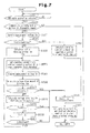
- steps S510 to S550 and S660 are similar to the processes of steps S10 to S50 and S130 of Fig. 5 .
- the sub-CPU 26 acquires the measurement voltage Vm (S530).
- the sub-CPU 26 calculates the charging current Ib based on the suppliable current Ig of the genuine AC adapter 23a (S550), and performs the setting of the charging current Ib and instructs the charge control IC 53 to start charging (S660) to charge the rechargeable battery with the supply voltage from the genuine AC adapter 23a.
- the voltage drop amount ⁇ V indicates the voltage drop amount represented by the difference between the measurement voltage Vm obtained before charging is started and the measurement voltage Vp obtained in the present test charging.
- the measurement voltage Vm in step S530 corresponds to the "initial power supply voltage”.
- the voltage drop amount ⁇ V of step S590 corresponds to the "voltage drop amount or the difference between the initial power supply voltage and the power supply voltage during charging".
- step S600 the sub-CPU 26 determines whether or not the voltage drop amount ⁇ V is greater than or equal to a threshold value ⁇ Vo. If the voltage drop amount ⁇ V is greater than or equal to the threshold value ⁇ Vo (set drop amount), this indicates that the power supply voltage Vbus has been lowered to an extent in which the charging of the rechargeable battery 41 becomes unstable. The sub-CPU 26 proceeds to step S610 if ⁇ V ⁇ Vo is not satisfied and proceeds to step S650 if ⁇ V2 ⁇ Vo is satisfied.
- Vpold is the previous measurement voltage Vp
- Vpnew is the present measurement voltage Vp
- ⁇ I is the incremented amount of the present charging current I from the preceding charging current I.
- n is the number of times test charging is performed.
- the ⁇ I is a constant in the test charging In which the charging current is increased by ⁇ I.
- the previous measurement voltage V n-1 is the power supply voltage Vbus measured when performing charging with charging current I n-1 .
- the present measurement voltage V n is the power supply voltage Vbus measured when performing charging with the charging current I n .
- the voltage drop rate Rv is a value indicating the proportion (ratio) of the voltage change amount between the previous measurement voltage V n-1 and the present measurement voltage V n for the change amount (incremented current value) ⁇ I of the previous charging current I n-1 and the present charging current I n .
- the charging current is raised by ⁇ I and the measurement voltage Vp (measurement value of power supply voltage Vbus) thereby suddenly falls for a large amount, this may indicate that the consumption current of the electronic still camera 11 has exceeded the USB specified current and the power supply voltage Vbus has become unstable. Therefore, in the present embodiment, the sub-CPU 26 determines that the charging current has entered the unstable range in which stable charging cannot be performed when the voltage drop rate Rv becomes greater than or equal to the threshold value Rvo (set threshold value).
- step S620 the sub-CPU 26 determines whether or not the voltage drop rate Rv is greater than or equal to the threshold value Rvo. The sub-CPU 26 proceeds to step S630 when Rv ⁇ Rvo is not satisfied and proceeds to step S650 when Rv ⁇ Rvo is satisfied.
- ⁇ I current value increment
- the sub-CPU 26 proceeds to step S650.
- the rechargeable battery 41 is stably charged with the charging current Ib that is determined in this manner.
- an affirmative determination in step S600 corresponds to a state in which "the voltage drop amount is greater than or equal to the set drop amount".
- the wires 57 and 58, the A/D converter circuit 60, and the sub-CPU 26 form a measurement unit for acquiring the voltage drop amount ⁇ V and the voltage drop rate Rv, which serve as measurement values.
- the CPU 70 includes the USB controller 39, the A/D converter circuit 60, the Reset terminal, the Port 1 terminal, the Port 2 terminal, the SID terminal, the IN terminal, and the like.
- the CPU 70 implements the functions of both the main CPU 25 and the sub-CPU 26 of the first to third embodiments.
- the power supply voltage VDD1 standby voltage is supplied from the power supply circuit 40 to the CPU 70 in a power off state so that the CPU 70 performs the detection of a USB connector connection, the detection of a switch operation, the counting process of the timing counter, and the like.
- the power supply voltages VDD2 to VDDn are generated by the power supply IC 51 based on the enable signal from the Port 1 terminal and output to the corresponding power supplying destinations.
- the voltage (power supply voltage Vbus) at node C in the wire 57, which is capable of supplying the power supply voltage Vbus, is input to the A/D converter circuit 60 through the wire 58.
- the CPU 70 acquires the measurement voltage Vm.
- the CPU 70 performs the charging control process in accordance with the flowchart shown in Fig. 5 of the first embodiment or the flowchart shown in Fig. 6 of the second embodiment.
- the CPU 70 may calculate the voltage drop amount ⁇ V and the voltage drop rate Rv from the measurement voltage Vm and perform the charge control through the flowchart shown in Fig. 7 of the third embodiment.
- the power supply circuit 40 shown in Fig. 8 has a structure similar to that shown in Fig. 4 .
- the CPU 70 forms the detection unit, the measurement unit, the control unit, the power supply information acquiring unit, and the determination unit.
- ⁇ i ⁇ I
- the sub-CPU 26 may activate the main CPU 25 when detecting a US8 connection to perform USB communication with the other electronic device that serves as the connection origin and determine the charging current lb based on the suppliable current (specified current) of that electronic device in the same manner as the second embodiment. That is, the processes of S230 to S290 shown in Fig. 6 may be added between S520 and S530 in Fig. 7 .
- the measurement voltage Vm in the first and the second embodiments may be further added as a measurement value in the third embodiment.
- the charging current that was in the stable range preceding the present charging current l may be used for the actual charging.
- the preceding charging current may be used for the actual charging.
- the preceding charging current may be used for the actual charging.
- the communication cable is not limited to a USB cable.
- an IEEE 1394 cable may be used.
- the electronic device including the charger of the present invention is not limited to the electronic still camera (digital still camera), and may be an electronic device such as a mobile phone, a PDA, a portable game machine, and the like.
- a first aspect is a charger for an electronic device that charges a rechargeable battery arranged in the electronic device.
- the charger includes a detection unit which detects connection of another electronic device to the electronic device through a communication cable including a power supply line.
- a charging unit charges the rechargeable battery with power supply voltage from the power supply line of the communication cable.
- a measurement unit acquires a measurement value indicating a degree of a voltage drop of the power supply voltage occurred when the charging unit performs charging.
- a control unit instructs a charging current value for charging the rechargeable battery with the charging unit.
- the control unit monitors the measurement value obtained by the measurement unit while instructing the charging unit to increase the charging current value from an initial current value and determines the charging current value based on the monitored measurement value.
- the control unit when the monitored measurement value enters an unstable range in which the charging of the charging unit is not guaranteed, the control unit preferably determines the charging current value to be in a range in which the measurement value does not enter the unstable range and instructs the charging unit to charge the rechargeable battery with the determined charging current value.
- the measurement unit preferably acquires a dropped power supply voltage resulting from the charging as the measurement value.
- the control unit preferably determines the charging current value so that the measurement value becomes greater than or equal to a threshold value.
- the measurement unit preferably acquires a voltage drop amount, which is a difference between an initial power supply voltage when the detection unit detects connection of the other electronic device and a power supply voltage during charging, as the measurement value.
- the control unit preferably decreases the charging current value when the voltage drop amount becomes greater than or equal to a set drop amount.
- the measurement unit when the control unit increases the charging current value from a previous value I n-1 to a present value I n , the measurement unit preferably calculates, based on a previous power supply voltage V n-1 and a present power supply voltage V n , a voltage drop rate (V n-1 -V n )/(I n-1 -I n ) as the measurement value.
- the control unit determines the charging current value so that the voltage drop rate does not exceed the set threshold value.
- the charger according to any one the first to fifth aspects, further comprising a power supply information acquiring unit which acquires specified power supply information of the other electronic device by communicating with the other electronic device through the communication cable.
- a determination unit determines that the other electronic device is an AC adapter when the power supply information acquiring unit cannot perform communication with the other electronic device.
- control unit preferably determines the charging current value in accordance with specified current value information contained in the specified power supply information when the power supply information acquiring unit performs communication with the other electronic device,
- the measurement unit preferably measures the power supply voltage when the detection unit detects connection of the other electronic device.
- the control unit preferably determines that the other electronic device is a standard known AC adapter and instructs the charging unit for a charging current value corresponding to known specified power supply information of the standard known AC adapter.
- An electronic device including the charger according to any one of the first to the eighth aspects.
- a method for charging a rechargeable battery arranged in an electronic device includes detecting, by the electronic device, connection of another electronic device to the electronic device through a communication cable including a power supply line; starting, by the electronic device, charging of the rechargeable battery using a power supply voltage from the power supply line of the communication cable; acquiring, by the electronic device, a measurement value indicating a degree of a voltage drop of the power supply voltage occurred during charging; and determining, by the electronic device, a charging current value of the rechargeable battery based on the measurement value.
- the determining step includes monitoring the measurement value during the charging while increasing the charging current value from an initial current value, and updating the charging current value based on the monitored measurement value.
Landscapes
- Engineering & Computer Science (AREA)
- Power Engineering (AREA)
- Charge And Discharge Circuits For Batteries Or The Like (AREA)
- Secondary Cells (AREA)
Applications Claiming Priority (1)
| Application Number | Priority Date | Filing Date | Title |
|---|---|---|---|
| JP2008331509A JP2010154692A (ja) | 2008-12-25 | 2008-12-25 | 電子機器における充電装置、電子機器及び充電方法 |
Publications (2)
| Publication Number | Publication Date |
|---|---|
| EP2202864A2 true EP2202864A2 (fr) | 2010-06-30 |
| EP2202864A3 EP2202864A3 (fr) | 2013-11-13 |
Family
ID=41796616
Family Applications (1)
| Application Number | Title | Priority Date | Filing Date |
|---|---|---|---|
| EP09180106.8A Withdrawn EP2202864A3 (fr) | 2008-12-25 | 2009-12-21 | Chargeur pour dispositif électronique, dispositif électronique et procédé de chargement |
Country Status (4)
| Country | Link |
|---|---|
| US (2) | US20100164440A1 (fr) |
| EP (1) | EP2202864A3 (fr) |
| JP (1) | JP2010154692A (fr) |
| CN (1) | CN101820177B (fr) |
Cited By (7)
| Publication number | Priority date | Publication date | Assignee | Title |
|---|---|---|---|---|
| EP2493048A1 (fr) * | 2011-02-23 | 2012-08-29 | Research In Motion Limited | Procédé et système pour détecter une capacité de courant électrique source d'alimentation électrique |
| CN103502828A (zh) * | 2011-04-01 | 2014-01-08 | 英特尔公司 | 用于测量充电电流的方法和装置 |
| US8793086B2 (en) | 2011-02-23 | 2014-07-29 | Blackberry Limited | Method and system for detecting power supply source electrical current capacity |
| CN104242365A (zh) * | 2013-06-19 | 2014-12-24 | 深圳富泰宏精密工业有限公司 | 便携式电子装置及使用方法 |
| EP2800235A4 (fr) * | 2011-12-28 | 2015-11-11 | Zte Corp | Terminal mobile et dispositif de charge et procédé correspondant |
| CN106532848A (zh) * | 2016-12-14 | 2017-03-22 | 惠州Tcl移动通信有限公司 | 一种基于移动终端的充电器检测时机获取控制方法及系统 |
| EP3159999A4 (fr) * | 2014-07-16 | 2017-06-28 | Huawei Technologies Co., Ltd. | Procédé, appareil et dispositif de charge rapide de dispositif électronique |
Families Citing this family (47)
| Publication number | Priority date | Publication date | Assignee | Title |
|---|---|---|---|---|
| US8358107B2 (en) * | 2007-12-31 | 2013-01-22 | Intel Corporation | Bidirectional power management techniques |
| JP5628022B2 (ja) * | 2009-12-28 | 2014-11-19 | パナソニック株式会社 | 電子機器及び給電制御方法 |
| JP2012029676A (ja) | 2010-07-07 | 2012-02-16 | Sony Corp | 核酸濃縮回収用カートリッジ、核酸濃縮回収方法、及び該カートリッジの製造方法 |
| US8321603B2 (en) * | 2010-07-28 | 2012-11-27 | Freescale Semiconductor, Inc. | Rechargeable device and method for determining universal serial bus port type |
| CN102087639B (zh) * | 2010-11-30 | 2015-05-20 | 中兴通讯股份有限公司 | 一种启动usb状态机的方法及终端 |
| TWI554887B (zh) * | 2010-12-30 | 2016-10-21 | 群邁通訊股份有限公司 | 電子裝置充電系統及方法 |
| JP5843129B2 (ja) * | 2011-04-26 | 2016-01-13 | 株式会社リコー | 画像処理装置 |
| US9148026B2 (en) * | 2011-09-30 | 2015-09-29 | Fairchild Semiconductor Corporation | Charger detection with proprietary charger support |
| KR101835007B1 (ko) * | 2011-10-25 | 2018-03-07 | 삼성전자주식회사 | 휴대용 단말기에서 충전 전류를 제어하기 위한 장치 및 방법 |
| US20130169847A1 (en) * | 2011-11-30 | 2013-07-04 | I-Star Entertainment Llc | Digital camera with a projector |
| JP5912513B2 (ja) * | 2011-12-22 | 2016-04-27 | ローム株式会社 | 充電回路およびそれを利用した電子機器 |
| FR2985053B1 (fr) * | 2011-12-22 | 2015-08-07 | Sagemcom Documents Sas | Dispositif de stockage et d'echange de donnees |
| JP5975662B2 (ja) * | 2012-02-06 | 2016-08-23 | キヤノン株式会社 | 画像形成装置及び画像形成装置の制御方法 |
| US9312576B2 (en) * | 2012-02-15 | 2016-04-12 | Htc Corporation | Portable electronic devices capable of obtaining charging current value of charger and charging method thereof |
| JP5301008B1 (ja) * | 2012-04-27 | 2013-09-25 | 株式会社東芝 | 電子機器、充電制御装置および充電制御方法 |
| CN103427124B (zh) * | 2012-05-14 | 2015-08-26 | 微宏动力系统(湖州)有限公司 | 电池组充电方法 |
| US20140036126A1 (en) * | 2012-08-03 | 2014-02-06 | Martin Barry Abrams | Digital video camera with a projector |
| JP2014050232A (ja) * | 2012-08-31 | 2014-03-17 | Nec Saitama Ltd | 充電装置、充電方法及び充電プログラム |
| TWI513168B (zh) * | 2012-12-20 | 2015-12-11 | Compal Electronics Inc | 電源轉換裝置 |
| TWI571734B (zh) | 2013-02-05 | 2017-02-21 | 新唐科技股份有限公司 | 電源管理電路與方法以及電腦系統 |
| CN103208661A (zh) * | 2013-04-24 | 2013-07-17 | 惠州Tcl移动通信有限公司 | 一种智能终端及其进行大电流充电的方法 |
| CN104253458B (zh) * | 2013-06-28 | 2018-06-15 | 富泰华工业(深圳)有限公司 | Usb充电线缆的性能测试系统、测试方法及电子装置 |
| TWI489734B (zh) * | 2013-12-20 | 2015-06-21 | 緯創資通股份有限公司 | 充電裝置以及充電系統 |
| CN103779907B (zh) | 2014-01-28 | 2016-11-23 | 广东欧珀移动通信有限公司 | 终端及其电池充电控制装置与方法 |
| PH12016501486B1 (en) | 2014-01-28 | 2024-01-05 | Guangdong Oppo Mobile Telecommunications Corp Ltd | Terminal, power adapter and method for handling charging anomaly |
| ES2880466T3 (es) * | 2014-01-28 | 2021-11-24 | Guangdong Oppo Mobile Telecommunications Corp Ltd | Adaptador de alimentación y terminal |
| CN103762702B (zh) | 2014-01-28 | 2015-12-16 | 广东欧珀移动通信有限公司 | 电子设备充电装置及其电源适配器 |
| US9158325B1 (en) * | 2014-04-22 | 2015-10-13 | Infineon Technologies Ag | Cable quality detection and power consumer devices |
| JP6355410B2 (ja) * | 2014-04-25 | 2018-07-11 | ローム株式会社 | 充電回路、パワーマネージメント回路、およびそれを用いた電子機器 |
| US10020665B2 (en) * | 2014-05-20 | 2018-07-10 | Intel Corporation | Power delivery system |
| WO2015180015A1 (fr) * | 2014-05-26 | 2015-12-03 | 华为技术有限公司 | Adaptateur d'alimentation, câble et chargeur |
| JP5866548B1 (ja) * | 2014-09-12 | 2016-02-17 | パナソニックIpマネジメント株式会社 | ウェアラブルカメラ |
| CN105790345A (zh) * | 2014-12-26 | 2016-07-20 | 中兴通讯股份有限公司 | 一种充电控制方法及装置 |
| CN110299737A (zh) | 2015-03-27 | 2019-10-01 | 广东欧珀移动通信有限公司 | 电力管理的方法、装置和电子设备 |
| WO2016154820A1 (fr) | 2015-03-27 | 2016-10-06 | 广东欧珀移动通信有限公司 | Procédé et appareil de commande de charge, et câble de charge |
| RU2678776C1 (ru) * | 2015-05-19 | 2019-02-01 | Хуавэй Текнолоджиз Ко., Лтд. | Способ зарядки, зарядное устройство, и терминал |
| CN104965376B (zh) * | 2015-07-30 | 2017-08-08 | 广东欧珀移动通信有限公司 | 一种终端相机闪光灯的调节方法及系统 |
| JP6714469B2 (ja) * | 2016-08-24 | 2020-06-24 | キヤノン株式会社 | 電子機器およびその制御方法 |
| KR102582596B1 (ko) | 2016-10-07 | 2023-09-25 | 삼성전자주식회사 | 배터리 충전 방법 및 전자 장치 |
| JP6916629B2 (ja) * | 2017-02-17 | 2021-08-11 | キヤノン株式会社 | 電子機器および制御方法 |
| JP6884000B2 (ja) * | 2017-02-17 | 2021-06-09 | キヤノン株式会社 | 電子機器およびその制御方法 |
| JP6939093B2 (ja) * | 2017-05-29 | 2021-09-22 | セイコーエプソン株式会社 | 書画カメラ、書画カメラの制御方法、及び、電子機器 |
| JP2019062690A (ja) * | 2017-09-27 | 2019-04-18 | パナソニックIpマネジメント株式会社 | 充電装置および電子機器 |
| CN113824167B (zh) * | 2020-06-19 | 2024-04-30 | 青岛海信移动通信技术有限公司 | 一种充电电路和充电方法 |
| CN114301140B (zh) * | 2021-12-31 | 2023-12-01 | 福建新大陆支付技术有限公司 | 一种基于pos的电池充电管理方法 |
| PT119135A (pt) * | 2023-12-15 | 2025-06-16 | Altice Labs S A | Sistema de deteção de adaptador de energia errado |
| TWI870193B (zh) * | 2024-01-04 | 2025-01-11 | 華碩電腦股份有限公司 | 電子裝置及其供電優化方法 |
Citations (1)
| Publication number | Priority date | Publication date | Assignee | Title |
|---|---|---|---|---|
| JP2006243863A (ja) | 2005-03-01 | 2006-09-14 | Sony Corp | 周辺装置 |
Family Cites Families (20)
| Publication number | Priority date | Publication date | Assignee | Title |
|---|---|---|---|---|
| JPH099624A (ja) | 1995-06-16 | 1997-01-10 | Nec Gumma Ltd | ノートパソコン用acアダプタ |
| JPH11234922A (ja) * | 1998-02-13 | 1999-08-27 | Sony Corp | 充電回路 |
| US7072360B2 (en) * | 2000-09-22 | 2006-07-04 | Narad Networks, Inc. | Network architecture for intelligent network elements |
| US6948000B2 (en) * | 2000-09-22 | 2005-09-20 | Narad Networks, Inc. | System and method for mapping end user identifiers to access device identifiers |
| US20020124111A1 (en) * | 2000-09-22 | 2002-09-05 | Narad Networks, Inc. | System and method for message transmission based on intelligent network element device identifiers |
| TW479393B (en) * | 2000-09-27 | 2002-03-11 | Acer Peripherals Inc | Automatic USB charging apparatus and its operating method |
| US7421594B2 (en) * | 2002-08-21 | 2008-09-02 | Fujitsu Limited | Bus power device and power-source control method |
| JP4153262B2 (ja) * | 2002-08-21 | 2008-09-24 | 富士通株式会社 | バスパワー装置 |
| JP4119711B2 (ja) | 2002-08-28 | 2008-07-16 | 株式会社アイ・オー・データ機器 | 情報伝達コネクタの電力供給機構及び情報伝達コネクタ |
| JP2004272829A (ja) * | 2003-03-12 | 2004-09-30 | Omron Corp | 誤接続判定方法および電子機器 |
| JP2007060778A (ja) * | 2005-08-23 | 2007-03-08 | Ricoh Co Ltd | 充電装置 |
| EP1780867B1 (fr) * | 2005-10-28 | 2016-11-30 | Black & Decker Inc. | Bloc batterie pour un outil de puissance sans raccord |
| KR100782271B1 (ko) * | 2005-11-28 | 2007-12-04 | 엘지전자 주식회사 | 휴대 단말기의 충전 제어 장치 및 방법 |
| US7834591B2 (en) * | 2006-02-16 | 2010-11-16 | Summit Microelectronics, Inc. | Switching battery charging systems and methods |
| JP2007288982A (ja) * | 2006-04-20 | 2007-11-01 | Nec Saitama Ltd | 充電回路およびその充電方法 |
| JP2008211950A (ja) | 2007-02-28 | 2008-09-11 | Nikon Corp | 電子機器 |
| WO2008131334A1 (fr) * | 2007-04-19 | 2008-10-30 | Summit Microelectronics, Inc. | Systèmes de chargement de batterie et procédés avec limite de courant réglable |
| JP4333777B2 (ja) * | 2007-05-22 | 2009-09-16 | ソニー株式会社 | 充電装置 |
| KR101397932B1 (ko) * | 2007-07-04 | 2014-05-22 | 삼성전자주식회사 | 외부 접속 장치 판별 방법 및 이를 이용하는 전자 장치 |
| CN101282045B (zh) * | 2008-04-28 | 2010-08-11 | 炬力集成电路设计有限公司 | 一种电池充电装置及其控制方法 |
-
2008
- 2008-12-25 JP JP2008331509A patent/JP2010154692A/ja active Pending
-
2009
- 2009-12-17 US US12/654,355 patent/US20100164440A1/en not_active Abandoned
- 2009-12-21 EP EP09180106.8A patent/EP2202864A3/fr not_active Withdrawn
- 2009-12-24 CN CN200910252596.3A patent/CN101820177B/zh active Active
-
2012
- 2012-08-31 US US13/601,760 patent/US8698460B2/en active Active
Patent Citations (1)
| Publication number | Priority date | Publication date | Assignee | Title |
|---|---|---|---|---|
| JP2006243863A (ja) | 2005-03-01 | 2006-09-14 | Sony Corp | 周辺装置 |
Cited By (15)
| Publication number | Priority date | Publication date | Assignee | Title |
|---|---|---|---|---|
| US8793086B2 (en) | 2011-02-23 | 2014-07-29 | Blackberry Limited | Method and system for detecting power supply source electrical current capacity |
| EP2493048A1 (fr) * | 2011-02-23 | 2012-08-29 | Research In Motion Limited | Procédé et système pour détecter une capacité de courant électrique source d'alimentation électrique |
| CN103502828B (zh) * | 2011-04-01 | 2016-07-06 | 英特尔公司 | 用于测量充电电流的方法和装置 |
| EP2694991A4 (fr) * | 2011-04-01 | 2014-10-08 | Intel Corp | Procédé et appareil pour mesurer un courant de charge |
| CN103502828A (zh) * | 2011-04-01 | 2014-01-08 | 英特尔公司 | 用于测量充电电流的方法和装置 |
| EP2800235A4 (fr) * | 2011-12-28 | 2015-11-11 | Zte Corp | Terminal mobile et dispositif de charge et procédé correspondant |
| US9450441B2 (en) | 2011-12-28 | 2016-09-20 | Zte Corporation | Mobile terminal, and device and method for charging same |
| CN104242365A (zh) * | 2013-06-19 | 2014-12-24 | 深圳富泰宏精密工业有限公司 | 便携式电子装置及使用方法 |
| CN104242365B (zh) * | 2013-06-19 | 2019-01-04 | 深圳富泰宏精密工业有限公司 | 便携式电子装置及使用方法 |
| EP3159999A4 (fr) * | 2014-07-16 | 2017-06-28 | Huawei Technologies Co., Ltd. | Procédé, appareil et dispositif de charge rapide de dispositif électronique |
| US10333326B2 (en) | 2014-07-16 | 2019-06-25 | Huawei Technologies Co., Ltd. | Devices and methods for fast charging using determined maximum charging current values |
| US11621568B2 (en) | 2014-07-16 | 2023-04-04 | Honor Device Co., Ltd. | Electronic device fast charging method, apparatus, and device |
| US12308672B2 (en) | 2014-07-16 | 2025-05-20 | Honor Device Co., Ltd. | Electronic device fast charging method, apparatus, and device |
| CN106532848A (zh) * | 2016-12-14 | 2017-03-22 | 惠州Tcl移动通信有限公司 | 一种基于移动终端的充电器检测时机获取控制方法及系统 |
| CN106532848B (zh) * | 2016-12-14 | 2020-09-22 | 惠州Tcl移动通信有限公司 | 一种基于移动终端的充电器检测时机获取控制方法及系统 |
Also Published As
| Publication number | Publication date |
|---|---|
| CN101820177B (zh) | 2014-08-20 |
| US8698460B2 (en) | 2014-04-15 |
| US20100164440A1 (en) | 2010-07-01 |
| JP2010154692A (ja) | 2010-07-08 |
| EP2202864A3 (fr) | 2013-11-13 |
| CN101820177A (zh) | 2010-09-01 |
| US20120326656A1 (en) | 2012-12-27 |
Similar Documents
| Publication | Publication Date | Title |
|---|---|---|
| EP2202864A2 (fr) | Chargeur pour dispositif électronique, dispositif électronique et procédé de chargement | |
| JP5843129B2 (ja) | 画像処理装置 | |
| US11239684B2 (en) | Electronic device and control method | |
| US9047073B2 (en) | System method for detecting a type of device wherein a potential level of the device determines if power should be supplied based on the type of the device | |
| US20180081326A1 (en) | Apparatus and control method for apparatus | |
| US11500438B2 (en) | Electronic apparatus and method for controlling the same | |
| US11189864B2 (en) | Electronic device and control method | |
| CN102263902A (zh) | 电子设备、附件和相机系统 | |
| US10886738B2 (en) | Electronic device and control method | |
| CN114865755A (zh) | 多电池电源及充放电方法和电子设备 | |
| CN114844182A (zh) | 充电电路、充电方法及电子设备 | |
| KR100584324B1 (ko) | 복합 단말기의 전원 제어 장치 | |
| US20190097276A1 (en) | Charging device and electronic device | |
| US20220037905A1 (en) | Electronic device and control method | |
| JP2011083093A (ja) | 充電制御方法及び充電制御回路 | |
| US7679321B2 (en) | Power circuit | |
| CN111886852B (zh) | 摄像装置 | |
| JP4116961B2 (ja) | バスパワード装置 | |
| JP2013080392A (ja) | 携帯装置のusb充電 | |
| CN102566209A (zh) | 成像设备和计算成像设备的可使用时间的方法 | |
| JP7769506B2 (ja) | 電子機器、制御方法およびプログラム | |
| EP1696571A1 (fr) | Dispositif alimenté par une batterie | |
| JP2018205836A (ja) | 電子機器及びその制御方法 | |
| US12085837B2 (en) | Adaptor device, imaging apparatus, and method for controlling same | |
| JP2022047802A (ja) | 電子機器、電池パック、制御方法およびプログラム |
Legal Events
| Date | Code | Title | Description |
|---|---|---|---|
| PUAI | Public reference made under article 153(3) epc to a published international application that has entered the european phase |
Free format text: ORIGINAL CODE: 0009012 |
|
| AK | Designated contracting states |
Kind code of ref document: A2 Designated state(s): AT BE BG CH CY CZ DE DK EE ES FI FR GB GR HR HU IE IS IT LI LT LU LV MC MK MT NL NO PL PT RO SE SI SK SM TR |
|
| AX | Request for extension of the european patent |
Extension state: AL BA RS |
|
| RAP1 | Party data changed (applicant data changed or rights of an application transferred) |
Owner name: NIKON CORPORATION |
|
| PUAL | Search report despatched |
Free format text: ORIGINAL CODE: 0009013 |
|
| AK | Designated contracting states |
Kind code of ref document: A3 Designated state(s): AT BE BG CH CY CZ DE DK EE ES FI FR GB GR HR HU IE IS IT LI LT LU LV MC MK MT NL NO PL PT RO SE SI SK SM TR |
|
| AX | Request for extension of the european patent |
Extension state: AL BA RS |
|
| RIC1 | Information provided on ipc code assigned before grant |
Ipc: H02J 7/00 20060101AFI20131008BHEP |
|
| 17P | Request for examination filed |
Effective date: 20140502 |
|
| RBV | Designated contracting states (corrected) |
Designated state(s): AT BE BG CH CY CZ DE DK EE ES FI FR GB GR HR HU IE IS IT LI LT LU LV MC MK MT NL NO PL PT RO SE SI SK SM TR |
|
| RAP1 | Party data changed (applicant data changed or rights of an application transferred) |
Owner name: NIKON CORPORATION |
|
| STAA | Information on the status of an ep patent application or granted ep patent |
Free format text: STATUS: THE APPLICATION HAS BEEN WITHDRAWN |
|
| 18W | Application withdrawn |
Effective date: 20151027 |