EP2202895A2 - Appareil de station de relais radio et procédé de relais radio - Google Patents
Appareil de station de relais radio et procédé de relais radio Download PDFInfo
- Publication number
- EP2202895A2 EP2202895A2 EP09178657A EP09178657A EP2202895A2 EP 2202895 A2 EP2202895 A2 EP 2202895A2 EP 09178657 A EP09178657 A EP 09178657A EP 09178657 A EP09178657 A EP 09178657A EP 2202895 A2 EP2202895 A2 EP 2202895A2
- Authority
- EP
- European Patent Office
- Prior art keywords
- station apparatus
- signal
- radio
- mobile station
- unit
- Prior art date
- Legal status (The legal status is an assumption and is not a legal conclusion. Google has not performed a legal analysis and makes no representation as to the accuracy of the status listed.)
- Withdrawn
Links
Images






Classifications
-
- H—ELECTRICITY
- H04—ELECTRIC COMMUNICATION TECHNIQUE
- H04B—TRANSMISSION
- H04B7/00—Radio transmission systems, i.e. using radiation field
- H04B7/14—Relay systems
- H04B7/15—Active relay systems
- H04B7/155—Ground-based stations
- H04B7/15528—Control of operation parameters of a relay station to exploit the physical medium
- H04B7/15542—Selecting at relay station its transmit and receive resources
-
- H—ELECTRICITY
- H04—ELECTRIC COMMUNICATION TECHNIQUE
- H04B—TRANSMISSION
- H04B7/00—Radio transmission systems, i.e. using radiation field
- H04B7/14—Relay systems
- H04B7/15—Active relay systems
- H04B7/155—Ground-based stations
- H04B7/15564—Relay station antennae loop interference reduction
- H04B7/15585—Relay station antennae loop interference reduction by interference cancellation
-
- Y—GENERAL TAGGING OF NEW TECHNOLOGICAL DEVELOPMENTS; GENERAL TAGGING OF CROSS-SECTIONAL TECHNOLOGIES SPANNING OVER SEVERAL SECTIONS OF THE IPC; TECHNICAL SUBJECTS COVERED BY FORMER USPC CROSS-REFERENCE ART COLLECTIONS [XRACs] AND DIGESTS
- Y02—TECHNOLOGIES OR APPLICATIONS FOR MITIGATION OR ADAPTATION AGAINST CLIMATE CHANGE
- Y02D—CLIMATE CHANGE MITIGATION TECHNOLOGIES IN INFORMATION AND COMMUNICATION TECHNOLOGIES [ICT], I.E. INFORMATION AND COMMUNICATION TECHNOLOGIES AIMING AT THE REDUCTION OF THEIR OWN ENERGY USE
- Y02D30/00—Reducing energy consumption in communication networks
- Y02D30/70—Reducing energy consumption in communication networks in wireless communication networks
Definitions
- the present invention relates to a radio relay station apparatus and a radio relay method for receiving a radio signal, which is transmitted and received between a base station apparatus and a mobile station apparatus, and sending the radio signal after amplifying the radio signal.
- a radio frequency (RF) direct amplification method that is of a non-regenerative relay method and a baseband regenerative relay method are known as a method for relaying the radio signal.
- the received radio signal is amplified without regeneration.
- the baseband regenerative relay method the received signal is returned to a baseband signal by demodulation and decoding, and coding and modulation are performed after the original signal is regenerated by correcting errors and the like.
- TMCC Transmission and Multiplexing Configuration Control
- the RF direct amplification method is a simple configuration which results in minimal processing delay.
- power consumption in the relay is increased because unnecessary signals that are not the relay target are also amplified.
- a frequency band occupancy in the relay is less efficient because the unnecessary signals that are not the relay target are also amplified.
- a radio relay method for relaying a radio signal in a radio relay station apparatus that relays the radio signal between a base station apparatus and a mobile station apparatus
- the radio relay method includes storing an identification of the mobile station apparatus, specifying a radio resource assigned to the mobile station apparatus, which is a radio resource in which a radio signal that should be amplified is transmitted, the radio resource assigned to the mobile station apparatus being indicated by control channel information sent from the base station apparatus, and receiving the radio signal between the base station apparatus and the mobile station apparatus.
- the radio relay method also includes amplifying the received signal, the received signal being transmitted on the specified radio resource, and sending the amplified signal in a form of the radio signal.
- FIG. 1 is an overall view illustrating a configuration of a radio relay station apparatus according to a first embodiment of the invention.
- a radio relay station apparatus 1 relays a radio signal that is sent from a base station apparatus (BS) to a mobile station apparatus (hereinafter also referred to as user equipment (UE)) on a downlink. That is, the radio relay station apparatus 1 receives the radio signal sent from the base station apparatus (BS) to the mobile station apparatus (UE), and sends the radio signal to the mobile station apparatus (UE) after amplifying the radio signal.
- the radio relay station apparatus 1 relays the radio signal sent from the mobile station apparatus (UE) to the base station apparatus (BS) on an uplink. That is, the radio relay station apparatus 1 receives the radio signal sent from the mobile station apparatus (UE) to the base station apparatus (BS), and sends the radio signal to the base station apparatus (BS) after amplifying the radio signal.
- the radio relay station apparatus 1 includes antennas 10 and 17, duplexers (DUP) 11 and 16, linear amplifiers 12 and 18, analog-digital conversion units (A/D) 13 and 19, Fourier transform units (FFT) 14 and 20, an inverse Fourier transform unit (IFFT) 21, a digital-analog conversion unit (D/A) 22, and a power amplifier 23.
- the radio relay station apparatus 1 also includes an amplifying unit 15, an identification information registering unit 24, an identification information database 25, and a radio resource specifying unit 26.
- the mobile station apparatus (UE) is connected to the base station apparatus (BS) by Orthogonal Frequency Division Multiple Access (OFDMA).
- OFDMA Orthogonal Frequency Division Multiple Access
- the mobile station apparatus (UE) and the base station apparatus (BS) may be communicating pursuant to a communication standard defined by Long Term Evolution (LTE) that is being standardized in the 3rd Generation Partnership Project (3GPP).
- LTE Long Term Evolution
- 3GPP 3rd Generation Partnership Project
- the radio relay station apparatus of the embodiments is not limited to that used in a communication system that is pursuant to LTE, but the radio relay station apparatus in the embodiments can be applied to various communication systems in which, using a control signal, the base station apparatus (BS) notifies the mobile station apparatus (UE) of a radio resource assigned to the mobile station apparatus (UE) on the uplink and/or the downlink.
- the antenna 10 receives the radio signal sent from the base station apparatus (BS) to the mobile station apparatus (UE) on the downlink.
- the linear amplifier 12 amplifies the received signal input through the duplexer 11.
- the analog-digital conversion unit 13 converts the signal amplified by the linear amplifier 12 into a digital signal.
- the Fourier transform unit 14 performs Fourier transform of an OFDMA signal converted into the digital signal by the analog-digital conversion unit 13, thereby converting the OFDMA signal into a symbol of each sub-carrier.
- the amplifying unit 15 converts the symbol of each sub-carrier, output from the Fourier transform unit 14, into the OFDMA signal by inverse Fourier transform.
- the amplifying unit 15 amplifies the OFDMA signal. A configuration of the amplifying unit 15 is described later.
- the antenna 17 sends the OFDMA signal, supplied through the duplexer 16 and amplified by the amplifying unit 15, to the mobile station apparatus (UE) .
- the antenna 17 receives the radio signal sent from the mobile station apparatus (UE) to the base station apparatus (BS) on the uplink.
- the linear amplifier 18 amplifies the received signal input through the duplexer 16.
- the analog-digital conversion unit 19 converts the signal amplified by the linear amplifier 18 into the digital signal.
- the Fourier transform unit 20 performs the Fourier transform of the OFDMA signal converted into the digital signal by the analog-digital conversion unit 19, thereby converting the OFDMA signal into the symbol of each sub-carrier.
- the inverse Fourier transform unit 21 converts the symbol of each sub-carrier, output from the Fourier transform unit 20, into the OFDMA signal by the inverse Fourier transform.
- the digital-analog conversion unit 22 converts the OFDMA signal output from the inverse Fourier transform unit 21 into the analog signal.
- the power amplifier 23 amplifies the analog-format OFDMA signal converted by the digital-analog conversion unit 22.
- the antenna 10 sends the OFDMA signal, supplied through the duplexer 11 and amplified by the power amplifier 23, to the base station apparatus (BS).
- the OFDMA signal is used by way of example. However, there is substantially no difference from a Single Carrier Frequency Division Multiple Access (SC-FDMA) signal that is used in an uplink communication method pursuant to LTE.
- SC-FDMA Single Carrier Frequency Division Multiple Access
- the identification information registering unit 24 obtains the identification information on the mobile station apparatus (UE), which is transmitted on the uplink.
- the identification information registering unit 24 registers the obtained identification information in the identification information database (DB) 25.
- the mobile station apparatus (UE) notifies the base station apparatus (BS) of the identification information on the mobile station apparatus (UE) through a random access channel (RACH) on the uplink.
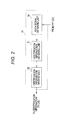
- FIG. 2 illustrates an example of a configuration of the identification information registering unit 24 of FIG. 1 .
- the identification information registering unit 24 includes an RANCH signal obtaining unit 30, an identification information obtaining unit 31, and an identification information writing unit 32.
- the RACH signal obtaining unit 30 obtains an RACH signal, transmitted through the random access channel, from a signal received from the mobile station apparatus (UE) on the uplink.
- the identification information obtaining unit 31 obtains the identification information on the mobile station apparatus (UE) of a source host.
- the identification information on the mobile station apparatus (UE) of the source host is included in the RACH signal obtained by the RANCH signal obtaining unit 30.
- the identification information writing unit 32 writes the identification information obtained by the identification information obtaining unit 31 in the identification information database 25 as the identification information on the mobile station apparatus that relays communication with the base station apparatus (BS) through the radio relay station apparatus 1.
- the identification information registering unit 24 registers the mobile station apparatus (UE) located within a range capable of communicating with the radio relay station apparatus 1 in the identification information database 25 as the mobile station apparatus (UE) whose communication with the base station apparatus (BS) is relayed by the radio relay station apparatus 1.
- the radio resource specifying unit 26 specifies a radio resource used in the transmission of the signal that should be amplified by the radio relay station apparatus 1 in the OFDMA signal received from the base station apparatus (BS).
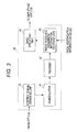
- FIG. 3 illustrates an example of a configuration of the radio resource specifying unit 26 of FIG. 1 .
- the radio resource specifying unit 26 includes a control signal obtaining unit 40, a demodulator 41, a decoder 42, a radio resource assignment information obtaining unit 43, and a band specifying unit 44.
- the control signal obtaining unit 40 obtains a control signal sent from the base station apparatus (BS) to the mobile station apparatus (UE) on the downlink.
- the demodulator 41 demodulates the control signal obtained from the control signal obtaining unit 40, and the decoder 42 decodes the control signal.
- the radio resource assignment information obtaining unit 43 obtains identification information on each mobile station apparatus (UE) connected to the base station apparatus (BS) and radio resource assignment information for providing an instruction of a frequency band assigned on the downlink to each mobile station apparatus (UE) from the decoded control signal.
- the radio resource assignment information obtaining unit 43 reads the identification information on the mobile station apparatus (UE), which is registered as the mobile station apparatus relayed by the radio relay station apparatus 1 from the identification information baseband 25.
- the radio resource assignment information obtaining unit 43 compares the identification information included in the decoded control signal and the identification information on the mobile station apparatus (UE) registered in the identification information database 25.
- the radio resource assignment information obtaining unit 43 obtains the radio resource assignment information that is stored in control information while correlated with the identification information, when the identification information included in the control signal is matched with the identification information registered in the identification information database 25.
- the radio resource assignment information obtaining unit 43 identifies the frequency band assigned to the mobile station apparatus (UE) registered in the identification information database 25 according to the radio resource assignment information.
- the band specifying unit 44 specifies the frequency band used in the transmission of the identification information as the frequency band that should be amplified by the amplifying unit 15. In a period during which the data is sent on the downlink in the frequency band assigned to each mobile station apparatus (UE), the band specifying unit 44 specifies the frequency band identified by the radio resource assignment information obtaining unit 43 as the frequency band that should be amplified by the amplifying unit 15.
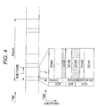
- FIG. 4 illustrates an example of a frame format of the radio signal.
- the frame format expresses a frame format of the radio signal on the downlink defined by LTE.
- One frame includes plural sub-frames, and one sub-frame includes a control signal portion 50 and a data portion 51.
- a control channel is mapped in the control signal portion 50.
- the control channel includes a broadcast channel (BCH) through which broadcast information is transmitted, a common control channel (CCH) through which control information shared by each mobile station apparatus (UE) is transmitted, and a dedicated control channel (CCH#1 to CCH#n) through which control information on each of mobile station apparatuses #1 to #n is transmitted.
- the common control channel CCH includes the identification information on the mobile station apparatus (UE), in which the sending data is included in the data portion 51 of the sub-frame.
- the dedicated control channels CCH#1 to CCH#n respectively include pieces of information for indicating the frequency bands assigned to the mobile station apparatuses #1 to #n whose pieces of identification information are specified in the common control channel CCH.
- Data channels (DCH#1 to DCH#n) assigned to the mobile station apparatuses #1 to #n, respectively, are mapped in the data portion 51.
- FIG. 5 illustrates an example of a configuration of the amplifying unit 15 of FIG. 1 .
- the amplifying unit 15 amplifies the signal in the frequency band specified by the band specifying unit 44 in the OFDMA signal that is converted into the signal expressing the symbol of each sub-carrier by the Fourier transform unit 14.
- the amplifying unit 15 includes a multiplier 60, an inverse Fourier transform unit 61, a digital-analog conversion unit 62, and a power amplifier 63.
- the band specifying unit 44 may output the band specifying information to the amplifying unit 15 as a coefficient that is multiplied by the symbol of each sub-carrier output from the Fourier transform unit 14.
- the band specifying information may include a coefficient of non-zero as a coefficient for the symbol of each sub-carrier corresponding to the amplified frequency band and zero as a coefficient for other symbols.
- the multiplier 60 multiplies the symbol of each sub-carrier output from the Fourier transform unit 14 and the band specifying information.
- the inverse Fourier transform unit 61 converts an operation result of the multiplier 60 into the OFDMA signal by the inverse Fourier transform.
- the digital-analog conversion unit 62 converts the OFDMA signal output from the inverse Fourier transform unit 61 into the analog signal.
- the power amplifier 63 amplifies the analog-format OFDMA signal converted by the digital-analog conversion unit 62 and outputs the analog-format OFDMA signal to the duplexer 16.
- the operation result of the multiplier 60 includes only the symbol of the sub-carrier corresponding to the frequency band specified by the band specifying unit 44, and other symbols are masked. Accordingly, the power amplifier 63 amplifies only the radio signal that is transmitted in the frequency band specified by the band specifying unit 44.
- FIG. 6 is a flowchart illustrating an operation of the radio relay station apparatus 1 of FIG. 1 .
- the identification information registering unit 24 obtains the identification information on the mobile station apparatus (BS) located within the range capable of communicating with the radio relay station apparatus 1 from the random access channel on the uplink.
- the identification information registering unit 24 registers the obtained identification information as the identification information on the mobile station apparatus (BS) of the relay target in the identification information database 25.
- Step S2 the radio relay station apparatus 1 receives the signal on the downlink.
- Step S3 the control signal obtaining unit 40, demodulator 41, and decoder 42 of the radio resource specifying unit 26 demodulate and decode the control signal included in the signal received in Step S2.
- the control signal obtaining unit 40, the demodulator 41, and the decoder 42 demodulate and decode the control signal portion 50.
- the radio resource assignment information obtaining unit 43 obtains the frequency band assigned to the mobile station apparatus (UE) registered in the identification information database 25, from the decoded control signal. For example, when the frame format of FIG. 4 is used, the radio resource assignment information obtaining unit 43 may obtain the identification information on the mobile station apparatus, which is included in the decoded control information on the common control channel (CCH). The radio resource assignment information obtaining unit 43 compares the identification information obtained from the control information and the identification information registered in the identification information database 25. When one of the pieces of identification information obtained from the control information is matched with the identification information registered in the identification information database 25, the radio resource assignment information obtaining unit 43 obtains the band information from the control information on the dedicated control channel for the mobile station apparatus (UE) in the identification information.
- CCH common control channel
- the band specifying unit 44 specifies the frequency band used in the transmission of the identification information as the frequency band that should be amplified by the amplifying unit 15 in the period during which the identification information is set on the downlink.
- the band specifying unit 44 specifies the frequency band identified by the radio resource assignment information obtaining unit 43 as the frequency band that should be amplified by the amplifying unit 15 in the period during which the data is sent on the downlink in the frequency band assigned to each mobile station apparatus (UE).
- Step S6 the amplifying unit 15 amplifies the frequency band specified by the band specifying unit 44 in the received signal.
- the radio relay station apparatus 1 sends the amplified radio signal on the downlink. Then the radio relay station apparatus 1 returns the processing to Step S2.
- only the frequency band used in the data for the mobile station apparatus (UE) registered as the relay target in the identification information database 25 is amplified in the signal of the data portion 51 of the sub-frame on the downlink of FIG. 4 , so that power consumption can be reduced in the power amplifier 63.
- only the frequency band used in the data for the mobile station apparatus (UE) registered in the identification information database 25 is amplified, so that the amplification of the unnecessary band can be eliminated to reduce the generation of the interference between the mobile station apparatuses (UE). Further, the demodulation processing and the decoding processing need not be performed on the data portion 51, so that the processing delay can be reduced.
- FIG. 7 is an overall view illustrating a configuration of a radio relay station apparatus according to a second embodiment of the invention.
- the radio relay station apparatus 1 of the second embodiment only the data that is sent from the mobile station apparatus (UE) registered in the identification information database 25 is relayed in the pieces of data sent on the uplink from the mobile station apparatuses (UE).
- the components similar to those of FIG. 1 are designated by the same reference numerals, and the descriptions are not repeated.
- the radio relay station apparatus 1 includes an inverse Fourier transform unit 27, a digital-analog conversion unit 28, and a power amplifier 29.
- the radio relay station apparatus 1 includes an amplifying unit 70.
- the inverse Fourier transform unit 27 converts the symbol of each sub-carrier output from the Fourier transform unit 14 into the OFDMA signal by the inverse Fourier transform.
- the digital-analog conversion unit 28 converts the OFDMA signal output from the inverse Fourier transform unit 27 into the analog signal.
- the power amplifier 29 amplifies the analog format OFDMA signal converted by the digital-analog conversion unit 28.
- the antenna 17 sends the OFDMA signal, supplied through the duplexer 16 and amplified by the power amplifier 29, to the mobile station apparatus (UE).
- the radio resource specifying unit 26 specifies the frequency band used in the transmission of the uplink signal from the mobile station apparatus (UE) as the frequency band that should be amplified by the amplifying unit 70.
- FIG. 8 illustrates an example of a configuration of the radio resource specifying unit 26 of FIG. 7 .
- the radio resource specifying unit 26 includes a control signal obtaining unit 71, a demodulator 72, a decoder 73, a radio resource assignment information obtaining unit 74, a sending time control unit 75, and a band specifying unit 76.
- the control signal obtaining unit 71 obtains the control signal that sent on the downlink from the base station apparatus (BS) to the mobile station apparatus (UE).
- the demodulator 72 demodulates the control signal obtained by the control signal obtaining unit 71, and the decoder 73 decodes the control signal.
- the radio resource assignment information obtaining unit 74 obtains sending permission information, in which the base station apparatus (BS) permits each mobile station apparatus (UE) to send the signal on the uplink, from the decoded control signal.
- the sending permission information includes time information for indicating a time the base station apparatus (BS) permits each mobile station apparatus (UE) to send the signal on the uplink and frequency band information on the frequency band used to send the signal. For example, in LTE, a UL grant signal may be used as the sending permission information.
- the radio resource assignment information obtaining unit 74 reads the identification information on the mobile station apparatus, which is registered as the mobile station apparatus relayed by the radio relay station apparatus 1, from the identification information database 25.
- the radio resource assignment information obtaining unit 74 compares the identification information included in the decoded control signal and the identification information on the mobile station apparatus (BS) registered in the identification information database 25.
- the radio resource assignment information obtaining unit 74 obtains the sending permission information that is stored in the control signal while correlated with the identification information.
- the radio resource assignment information obtaining unit 74 identifies the time each mobile station apparatus (UE) registered in the identification information database 25 is permitted to send the signal and the frequency band information on the frequency band used to send the signal according to the sending permission information.
- the sending time control unit 75 controls a time the band specifying unit 76 outputs the band specifying information to the amplifying unit 70 according to the sending time identified by the radio resource assignment information obtaining unit 74.
- the band specifying unit 76 outputs the band specifying information for specifying the band amplified by the amplifying unit 70 to the amplifying unit 70 in the sending time identified by the radio resource assignment information obtaining unit 74.
- the amplifying unit 70 is similar to the amplifying unit of FIG. 5 , and the amplifying unit 70 amplifies the signal in the frequency band specified by the band specifying unit 76 in the OFDMA signal that is converted into the signal expressing the symbol of each sub-carrier by the Fourier transform unit 20.
- FIG. 9 is a flowchart illustrating an operation of the radio relay station apparatus 1 of FIG. 7 .
- the identification information registering unit 24 registers the identification information on the mobile station apparatus (BS) located within the range capable of communicating with the radio relay station apparatus 1 in the identification information database 25.
- the radio relay station apparatus 1 receives the signal on the downlink.
- the control signal obtaining unit 71, demodulator 72, and decoder 73 of the radio resource specifying unit 26 demodulates and decodes the control signal included in the signal received in Step S2.
- the radio resource assignment information obtaining unit 74 obtains the sending permission information on the mobile station apparatus (UE) registered in the identification information database 25 from the decoded control signal.
- the radio resource assignment information obtaining unit 74 identifies the time each mobile station apparatus (UE) registered in the identification information database 25 is permitted to send the signal and the frequency band information on the frequency band used to send the signal according to the sending permission information.
- Step S14 the radio relay station apparatus 1 receives the signal on the uplink.
- Step S15 the sending time control unit 15 determines whether the current time reaches the sending time identified by the radio resource assignment information obtaining unit 74. The processing returns to Step S14 when the current time does not reach the sending time (N in Step S15), and the processing goes to Step S16 when the current time reaches the sending permission time (Y in Step S15).
- Step S16 the band specifying unit 76 outputs the band specifying information for specifying the frequency band identified in Step S13 to the amplifying unit 70 in the sending time identified by the radio resource assignment information obtaining unit 74.
- Step S17 the amplifying unit 70 amplifies the frequency band specified by the band specifying unit 76 in the received signal.
- Step S18 the radio relay station apparatus 1 sends the amplified radio signal on the uplink. Then the radio relay station apparatus 1 returns the processing to Step S11.
- the radio relay station apparatus 1 of FIG. 7 includes the components similar to those of the radio relay station apparatus of FIG. 1 , whereby the radio relay station apparatus 1 of FIG. 7 may relay only the data sent to the mobile station apparatus (UE) registered in the identification information database 25 in the pieces of data on the downlink like the radio relay station apparatus of FIG. 1 .
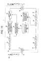
- FIG. 10 is an overall view illustrating a configuration of a radio relay station apparatus according to a third embodiment of the invention.
- the radio relay station apparatus 1 of the third embodiment includes a self interference suppression processing unit 80 as a downlink signal processing circuit.
- the self interference suppression processing unit 80 suppresses self interference in the received downlink signal.
- the components similar to those of FIG. 1 are designated by the same reference numerals, and the descriptions are not repeated.
- the self interference suppression processing unit 80 delays a time necessary for the loop of the signal component sent from the antenna 17 in a receiving circuit, and the self interference suppression processing unit 80 removes the delayed signal component from the received signal.
- the operation result of the multiplier 60 of FIG. 5 may be used in the interference suppression processing.
- the radio relay station apparatus 1 relays only the data sent to the mobile station apparatus (UE) of the relay target in the pieces of data transmitted on the downlink, thereby reducing the interference between the mobile station apparatus (UE).
- the self interference of the sending signal in the target mobile station apparatus (UE) is reduced to further improve the signal quality.
- the similar self interference suppression processing unit may be provided in the uplink signal processing circuit according to the second embodiment of FIG. 7 .
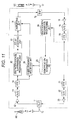
- FIG. 11 is an overall view illustrating a configuration of a radio relay station apparatus according to a fourth embodiment of the invention.
- the radio relay station apparatus 1 of the fourth embodiment includes a delay adjusting unit 81.
- the delay adjusting unit 81 delays the received signal input to the amplifying unit 15 for the time the radio resource specifying unit 26 demodulates, and decodes the control signal on the downlink to specify the frequency band to be amplified, and the delay adjusting unit 81 absorbs the delay of the frequency band specification with respect to the received signal input to the amplifying unit 15. According to the fourth embodiment of the invention, the delay of the frequency band specification generated in actually mounting the radio resource specifying unit 26 is absorbed.
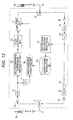
- FIG. 12 is an overall view illustrating a configuration of a radio relay station apparatus according to a fifth embodiment of the invention.
- the self interference suppression processing unit 80 performs self interference processing on the OFDMA signal of a time-domain signal output from the analog-digital conversion unit 13.
- the amplifying unit 15 amplifies the OFDMA signal converted into the digital-format signal while the OFDMA signal is kept the time-domain signal.
- the OFDMA signal is the RF signal converted into the digital-format signal by the analog-digital conversion unit 13.
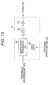
- FIG. 13 illustrates an example of a configuration of the amplifying unit 15 of FIG. 12 .
- the amplifying unit 15 includes an inverse Fourier transform unit 61, a digital-analog conversion unit 62, a power amplifier 63, and a convolution processing unit 82.
- the inverse Fourier transform unit 61 converts the band specifying information output from the band specifying unit 44 into the time-domain signal by the inverse Fourier transform.
- the convolution processing unit 82 performs filtering processing for passing the received signal in the specified band by performing convolution operation between the received signal of the time-domain signal output from the delay adjusting unit 81 and the time-domain signal output from the inverse Fourier transform unit 61.
- the digital-analog conversion unit 62 converts an output signal of the convolution processing unit 82 into an analog signal.
- the power amplifier 63 amplifies the analog-format OFDMA signal converted by the digital-analog conversion unit 62, and the power amplifier 63 outputs the amplified OFDMA signal to the duplexer 16.
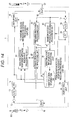
- FIG. 14 is an overall view illustrating a configuration of a radio relay station apparatus according to a sixth embodiment of the invention.
- the mobile station apparatus (UE) sends a preamble signal when the connection to the base station apparatus (BS) is started.
- the base station apparatus (BS) sends a random access response message for the preamble signal.
- the mobile station apparatus (UE) sends the random access message including an identification number thereof.
- the radio relay station apparatus 1 When receiving the preamble signal, the radio relay station apparatus 1 tentatively registers the mobile station apparatus (UE) that sends the preamble signal. When the mobile station apparatus (UE) sends the random access message, the radio relay station apparatus 1 obtains the identification number of the mobile station apparatus (UE), which is included in the random access message, and the radio relay station apparatus 1 registers the identification number of the mobile station apparatus (UE) in the identification information database 25.
- the radio relay station apparatus 1 includes a preamble receiving processing unit 90, a random access response message receiving processing unit 91, and a random access message receiving processing unit 92.
- the preamble receiving processing unit 90 detects the preamble signal that is transmitted on the uplink from the mobile station apparatus (UE). When detecting the preamble signal, the preamble receiving processing unit 90 registers a preamble pattern included in the preamble signal as the information for identifying the tentatively-registered mobile station apparatus (UE) in the identification information database 25. The preamble receiving processing unit 90 notifies the radio resource specifying unit 26 of the preamble pattern.
- FIG. 15 illustrates an example of a configuration of the radio resource specifying unit 26 of FIG. 14 .
- the radio resource specifying unit 26 includes a control signal obtaining unit 100, a demodulator 101, a decoder 102, and a broadcast channel (BCH) detecting unit 103.
- BCH broadcast channel
- the radio resource specifying unit 26 includes a DL radio resource assignment information obtaining unit 104, a random access response message relay control unit 105, a DL sending time control unit 106, and a DL band specifying unit 107.
- the radio resource specifying unit 26 includes a UL radio resource assignment information obtaining unit 108, a random access message relay control unit 109, a UL sending time control unit 110, a UL band specifying unit 111, and a preamble relay processing unit 112.
- the control signal obtaining unit 100 obtains the control signal that is sent on the downlink from the base station apparatus (BS) to the mobile station apparatus (UE).
- the demodulator 101 demodulates the control signal obtained by the control signal obtaining unit 100, and the decoder 102 decodes the control signal.
- the broadcast channel detecting unit 103 detects broadcast information included in the decoded control signal.
- the broadcast information includes a sending time the mobile station apparatus (UE) is permitted to send the preamble signal and information on the frequency band.
- the broadcast channel detecting unit 103 supplies the sending time the mobile station apparatus (UE) is permitted to send the preamble signal and information on the frequency band to the preamble relay processing unit 112.
- the broadcast information includes information for indicating an interval T1 from the time the base station apparatus (BS) receives the preamble signal until transmitting the random access response message in response to the preamble signal.
- the broadcast information includes information for indicating an interval T2 from the time the random access response message is received until the mobile station apparatus (UE) should send the random access message.
- the broadcast channel detecting unit 103 supplies the information for indicating an interval T1 from the time the base station apparatus (BS) receives the preamble signal until transmitting the random access response message in response to the preamble signal to the random access response message control unit 105.
- the broadcast channel detecting unit 103 supplies the information for indicating an interval T2 from the time the random access response message is received until the mobile station apparatus (UE) should send the random access message to the random access message control unit 109.
- the DL radio resource assignment information obtaining unit 104 obtains the frequency band assigned to the mobile station apparatus (BS) registered in the identification information database 25 from the control signal decoded by the decoder 102.
- the band specifying unit 107 specifies the frequency band identified by the DL radio resource assignment information obtaining unit 104 and the frequency band used in the transmission of the identification information as the frequency band that should be amplified by the amplifying unit 15.
- the random access response message relay control unit 105 determines the time the random access response message arrives based on the time information for indicating the time interval T1, which is supplied from the broadcast channel detecting unit 103, and the random access response message relay control unit 105 notifies the DL sending time control unit 106, the random access response message receiving processing unit 91, and the random access message relay control unit 109 of the determined time. In relaying the random access response message, the random access response message relay control unit 105 controls the DL band specifying unit 107 such that all the frequency bands used on the downlink are specified as the band amplified by the amplifying unit 15.
- the DL sending time control unit 106 controls the time the DL band specifying unit 107 outputs the band specifying information to the amplifying unit 15 in relaying the random access response message.
- the DL band specifying unit 107 outputs the band specifying information for specifying all the frequency bands used on the downlink to the amplifying unit 15 in the sending time specified by the random access response message relay control unit 105.
- the amplifying unit 15 amplifies the random access response message by amplifying all the frequency bands used on the downlink in the sending time of the random access response message.
- the UL radio resource assignment information obtaining unit 108 obtains the sending permission information on the mobile station apparatus (UE) registered in the identification information database 25.
- the UL sending time control unit 110 controls the time the UL band specifying unit 111 outputs the band specifying information to the amplifying unit 70 according to the sending time identified by the UL radio resource assignment information obtaining unit 108.
- the UL band specifying unit 111 outputs the band specifying information for specifying the band that should be amplified to the amplifying unit 70 in the sending time identified by the UL radio resource assignment information obtaining unit 108.
- the preamble relay processing unit 112 supplies the information for indicating the sending time in which the sending of the preamble signal is permitted, which is specified in the broadcast information, to the UL sending time control unit 110. In relaying the preamble signal, the preamble relay processing unit 112 controls the UL band specifying unit 111 such that the frequency band in which the sending of the preamble signal is permitted is specified as the band amplified by the amplifying unit 70.
- the UL sending time control unit 110 controls the UL band specifying unit 111 such that the UL band specifying unit 111 outputs the band specifying information to the amplifying unit 70 in the time the preamble signal can be sent.
- the UL band specifying unit 111 outputs the band specifying information for specifying the frequency band in which the sending of the preamble signal is permitted to the amplifying unit 70 in the preamble signal sending time specified by the broadcast information.
- the amplifying unit 70 amplifies the frequency band used in the transmission of the preamble signal on the uplink according to the band specifying information by the UL band specifying unit 111.
- the random access message relay control unit 109 determines the time the random access message arrives from the mobile station apparatus (UE) based on the time the random access response message supplied from the random access response message relay control unit 105 arrives and the time information for indicating the time interval T2, which is supplied from the broadcast channel detecting unit 103. From the random access response message receiving processing unit 91, the random access message relay control unit 109 may obtain the information for indicating the sending time the random access message is sent.
- the random access message relay control unit 109 supplies the information for indicating the time the random access message is sent.
- the random access message relay control unit 109 controls the UL band specifying unit 111 such that all the frequency bands used on the uplink are specified as the band amplified by the amplifying unit 15.
- FIG. 16 illustrates an example of a configuration of the random access response message receiving processing unit 91 of FIG. 14 .
- the random access response message sent from the base station apparatus (BS) to the mobile station apparatus (UE) includes information for specifying the frequency band in which the mobile station apparatus (UE) sends the random access message in response to the random access response message.
- the random access response message may include information for specifying the time the random access message is sent.
- the random access response message receiving processing unit 91 includes a data channel signal obtaining unit 120, a demodulator 121, a decoder 123, and a radio resource assignment information obtaining unit 124.
- the data channel signal obtaining unit 120 obtains the data channel signal sent on the downlink from the base station apparatus (BS) to the mobile station apparatus (UE).
- the demodulator 121 modulates the data channel signal obtained by the data channel signal obtaining unit 120, and the decoder 123 decodes the data channel signal.
- the radio resource assignment information obtaining unit 124 obtains the information for specifying the frequency band used to send the random access message from the random access response message included in the decoded data channel signal.
- the radio resource assignment information obtaining unit 124 supplies the information for specifying the frequency band used to send the random access message to the random access message receiving processing unit 92.
- the radio resource assignment information obtaining unit 124 may obtain the information for specifying the random access message sending time from the random access response message.
- the radio resource assignment information obtaining unit 124 may supply the information for specifying the random access message sending time to the random access message relay control unit 109.
- the UL sending time control unit 110 controls the time the UL band specifying unit 111 outputs the band specifying information to the amplifying unit 70 in relaying the random access message.
- the UL band specifying unit 111 outputs the band specifying information for specifying all the frequency bands used on the uplink to the amplifying unit 70 in the sending time specified by the random access message relay control unit 109.
- the amplifying unit 70 amplifies the random access message by amplifying all the frequency bands used on the uplink in the random access message sending time.
- FIG. 17 illustrates an example of a configuration of the random access message receiving processing unit 92 of FIG. 14 .
- the random access message receiving processing unit 92 includes a data channel signal obtaining unit 130, a demodulator 131, a decoder 132, and an identification information obtaining unit 133.
- the data channel signal obtaining unit 130 obtains the information for specifying the frequency band used to send the random access message from the random access response message receiving processing unit 91.
- the data channel signal obtaining unit 130 obtains the sent data channel signal in the time the random access message supplied from the random access message relay control unit 109 arrives in the specified frequency band.
- the demodulator 131 demodulates the data channel signal obtained by the data channel signal obtaining unit 130, and the decoder 132 decodes the data channel signal.
- the identification information obtaining unit 133 obtains the identification information on the mobile station apparatus (UE) that sends the random access message from the random access message included in the decoded data channel signal, and the identification information obtaining unit 133 supplies the identification information to the identification information registering unit 24.
- UE mobile station apparatus
- FIG. 18 illustrates an example of a configuration of the identification information registering unit 24 of FIG. 14 .
- the identification information registering unit 24 includes an identification information obtaining unit 31 and an identification information writing unit 32.
- the identification information obtaining unit 31 obtains the identification information from the random access message receiving processing unit 92.
- the identification information writing unit 32 writes the identification information obtained by the identification information obtaining unit 31 as the identification information on the mobile station apparatus whose communication with the base station apparatus (BS) is relayed by the radio relay station apparatus 1 in the identification information database 25.
- the identification information writing unit 32 erases the tentative registration of the mobile station apparatus (UE) registered by the preamble receiving processing unit 90.
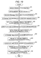
- FIG. 19 is a flowchart illustrating an example of identification information obtaining processing of the mobile station apparatus
- FIG. 20 illustrates an example of the identification information obtaining processing of the mobile station apparatus.
- Step S20 when the radio relay station apparatus 1 receives the broadcast information, the broadcast channel detecting unit 103 detects the broadcast information.
- the broadcast channel detecting unit 103 supplies the sending time in which the sending of the preamble signal is permitted and the information on the frequency band to the preamble relay processing unit 112.
- the broadcast information includes the sending time in which the sending of the preamble signal is permitted and the information on the frequency band.
- the broadcast channel detecting unit 103 supplies the interval T1 from the time the base station apparatus (BS) receives the preamble signal until sending the random access response message to the random access response message control unit 105.
- the broadcast information includes the interval T1.
- the broadcast channel detecting unit 103 supplies the interval T2 from the time the mobile station apparatus (UE) receives the random access response message until sending the random access message to the random access message control unit 109.
- the broadcast information includes the interval T2.
- Step S23 the radio relay station apparatus 1 receives the preamble signal.
- a time t1 expresses the time the preamble signal is received.
- the preamble relay processing unit 112, the UL sending time control unit 110, and the UL band specifying unit 111 controls the amplifying unit 70 such that the signal on the uplink is amplified in the sending time in which the sending of the preamble signal is permitted and a frequency band 140.
- Step S24 the random access response message relay control unit 105 determines a time t2 the random access response message arrives based on the time information for indicating the time interval T1 supplied from the broadcast channel detecting unit 103.
- Step S25 the random access response message relay control unit 105, the DL sending time control unit 106, and the DL band specifying unit 107 amplify the radio signals in all the bands used on the downlink in a sub-frame 141 in which the random access response message is sent.
- Step S26 the random access response message receiving processing unit 91 demodulates and decodes the random access response message received by the radio relay station apparatus 1.
- Step S27 the radio resource assignment information obtaining unit 124 of the random access response message receiving processing unit 91 obtains the information for specifying the frequency band used to send the random access message.
- the radio resource assignment information obtaining unit 124 may obtain the information for specifying the sending time of the random access message.
- the random access message relay control unit 109 determines a time t3 the random access message arrives based on the sending time of the random access response message and the time information for indicating the time interval T2 supplied from the broadcast channel detecting unit 103.
- the random access message relay control unit 109 may use a random access message sending time t3 imparted in the random access response message.
- Step S29 the random access message relay control unit 109, the UL sending time control unit 110, and the DL band specifying unit 111 amplify the radio signals of all the bands used on the uplink in the sub-frame 142 in which the random access message is sent.
- the random access message receiving processing unit 92 demodulates and decodes the random access message received by the radio relay station apparatus 1.
- the identification information obtaining unit 133 of the random access message receiving processing unit 92 obtains the identification information of the mobile station apparatus (UE).
- the random access message includes the identification information of the mobile station apparatus (UE).
- the identification information registering unit 24 registers the obtained identification information as the identification information of the mobile station apparatus (UE) that should be relayed by the radio relay station apparatus 1 in the identification information database 25.
- the radio relay station apparatus 1 of the sixth embodiment relays a control signal 144 and data 145, which are included in a sub-frame 143 on the downlink at a time t4.
- the radio relay station apparatus 1 of the sixth embodiment relays data 147 on the uplink at a time t5 according to the sending permission information included in the control signal 144 of the sub-frame 143.
- the radio relay station apparatus 1 can be used in a system in which the identification information on the mobile station apparatus UE is imparted in the random access message.
- the processing delay may be suppressed because only the control channel information is referred to in order to learn the radio resource assigned to the mobile station apparatus.
- the radio resource assigned to the target mobile station apparatus because the radio resource assigned to the target mobile station apparatus is relayed, the necessity to relay unnecessary signals that are not the relay target may be eliminated, and the power consumption may be reduced to improve the frequency use efficiency.
- the invention also provides a computer program or a computer program product for carrying out any of the methods described herein, and a computer readable medium having stored thereon a program for carrying out any of the methods described herein.
- a computer program embodying the invention may be stored on a computer-readable medium, or it could, for example, be in the form of a signal such as a downloadable data signal provided from an Internet website, or it could be in any other form.
Landscapes
- Engineering & Computer Science (AREA)
- Computer Networks & Wireless Communication (AREA)
- Signal Processing (AREA)
- Mobile Radio Communication Systems (AREA)
- Radio Relay Systems (AREA)
Applications Claiming Priority (1)
| Application Number | Priority Date | Filing Date | Title |
|---|---|---|---|
| JP2008331008A JP5439810B2 (ja) | 2008-12-25 | 2008-12-25 | 無線信号中継装置及び無線信号中継方法 |
Publications (2)
| Publication Number | Publication Date |
|---|---|
| EP2202895A2 true EP2202895A2 (fr) | 2010-06-30 |
| EP2202895A3 EP2202895A3 (fr) | 2011-01-05 |
Family
ID=42077487
Family Applications (1)
| Application Number | Title | Priority Date | Filing Date |
|---|---|---|---|
| EP09178657A Withdrawn EP2202895A3 (fr) | 2008-12-25 | 2009-12-10 | Appareil de station de relais radio et procédé de relais radio |
Country Status (4)
| Country | Link |
|---|---|
| US (1) | US20100167768A1 (fr) |
| EP (1) | EP2202895A3 (fr) |
| JP (1) | JP5439810B2 (fr) |
| CN (1) | CN101764644A (fr) |
Families Citing this family (15)
| Publication number | Priority date | Publication date | Assignee | Title |
|---|---|---|---|---|
| CA2807345C (fr) * | 2010-08-13 | 2017-01-03 | Fujitsu Limited | Systeme de communication sans fil, station de base, station de relais et methode de communication sans fil |
| CN105515635B (zh) * | 2010-08-13 | 2019-02-15 | 富士通互联科技有限公司 | 无线通信系统、基站、中继站以及无线通信方法 |
| WO2012059555A1 (fr) * | 2010-11-03 | 2012-05-10 | Telefonaktiebolaget L M Ericsson (Publ) | Suppression d'auto-brouillage dans des relais mimo à duplex intégral |
| WO2012096615A1 (fr) * | 2011-01-11 | 2012-07-19 | Telefonaktiebolaget L M Ericsson (Publ) | Configuration de bande passante et rapport pour liaisons relais |
| GB201201915D0 (en) | 2012-02-03 | 2012-03-21 | Nec Corp | Mobile communications device and system |
| CN104350779B (zh) * | 2012-04-09 | 2019-02-15 | 瑞典爱立信有限公司 | 管理不确定的测量时机 |
| IL222786A (en) * | 2012-11-01 | 2016-09-29 | Elta Systems Ltd | Enable Boost to Downlink channels on a cellular communication system |
| CN104144517B (zh) * | 2013-05-10 | 2019-05-10 | 中兴通讯股份有限公司 | 一种随机接入方法及系统 |
| SG10201709666PA (en) | 2013-05-23 | 2017-12-28 | Elta Systems Ltd | Receiver, system and method for frequency diversity communications using beacon and methods useful in conjunction therewith |
| CN106131962B (zh) * | 2015-05-05 | 2019-11-15 | 苹果公司 | Wlan ofdma中的控制信道 |
| WO2017044143A1 (fr) * | 2015-09-11 | 2017-03-16 | Intel IP Corporation | Accès de réseau radio de dispositifs pouvant être portés |
| US12047999B2 (en) | 2019-08-01 | 2024-07-23 | Qualcomm Incorporated | Access procedure configuration of a millimeter wave repeater |
| US12101165B2 (en) | 2019-08-01 | 2024-09-24 | Qualcomm Incorporated | Access procedure of smart directional repeaters |
| US12107661B2 (en) * | 2019-08-01 | 2024-10-01 | Qualcomm Incorporated | Control method for smart repeaters |
| US12309830B2 (en) | 2020-03-23 | 2025-05-20 | Qualcomm Incorporated | Access procedure configuration of a millimeter wave repeater |
Citations (4)
| Publication number | Priority date | Publication date | Assignee | Title |
|---|---|---|---|---|
| US6718158B1 (en) | 1998-05-14 | 2004-04-06 | Nokia Networks Oy | Method of monitoring operation of cellular radio system |
| US20080063097A1 (en) | 2004-09-29 | 2008-03-13 | Matsushita Electric Industrial Co., Ltd. | Radio Communication Device and Radio Communication Method |
| WO2008050425A1 (fr) | 2006-10-25 | 2008-05-02 | Fujitsu Limited | Station de base radio, station relais, système de communication radio, et procédé de communication radio |
| WO2009093406A1 (fr) | 2008-01-25 | 2009-07-30 | Ntt Docomo, Inc. | Système de transmission à relais, station de base, station de relais et procédé |
Family Cites Families (14)
| Publication number | Priority date | Publication date | Assignee | Title |
|---|---|---|---|---|
| US5459761A (en) * | 1992-06-29 | 1995-10-17 | Motorola, Inc. | Intelligent repeater for trunked communications |
| FI108098B (fi) * | 1994-03-03 | 2001-11-15 | Nokia Networks Oy | Menetelmä suorakanavalla liikennöivän tilaaja-aseman hallitsemiseksi, radiojärjestelmä ja tilaaja-asema |
| JP2671864B2 (ja) * | 1995-05-12 | 1997-11-05 | 日本電気株式会社 | 無線通信システム |
| US5697052A (en) * | 1995-07-05 | 1997-12-09 | Treatch; James E. | Cellular specialized mobile radio system |
| JP3041324B1 (ja) * | 1999-06-10 | 2000-05-15 | 三菱電機株式会社 | 無線中継装置 |
| JP2002271241A (ja) * | 2001-03-06 | 2002-09-20 | Matsushita Electric Ind Co Ltd | 中継装置 |
| US6907093B2 (en) * | 2001-08-08 | 2005-06-14 | Viasat, Inc. | Method and apparatus for relayed communication using band-pass signals for self-interference cancellation |
| JP4526303B2 (ja) * | 2004-05-27 | 2010-08-18 | 日本テレビ放送網株式会社 | ギャップフィラー装置、及びデジタル放送信号の再送信方法 |
| KR20060005925A (ko) * | 2004-07-14 | 2006-01-18 | 에스케이 텔레콤주식회사 | Tdd방식과 ofdm 변조 방식을 이용하는 이동통신망의 rf 중계기에서 전송 신호를 분리하는 스위칭타이밍 신호 생성 방법 및 시스템 |
| US8045918B2 (en) * | 2004-09-02 | 2011-10-25 | Samsung Electronics Co., Ltd. | Proxy mobile station using assignable mobile identifier to access a wireless network |
| JP4952138B2 (ja) * | 2006-08-17 | 2012-06-13 | 富士通株式会社 | 中継局、無線基地局及び通信方法 |
| KR101276339B1 (ko) * | 2006-09-29 | 2013-06-18 | 한국전자통신연구원 | 기지국과 단말을 중계하는 장치 및 방법, 그리고 기지국 |
| JP2008227973A (ja) * | 2007-03-13 | 2008-09-25 | Japan Radio Co Ltd | 中継装置 |
| US20090122744A1 (en) * | 2007-11-09 | 2009-05-14 | Alexander Maltsev | Selective relaying for wireless networks |
-
2008
- 2008-12-25 JP JP2008331008A patent/JP5439810B2/ja not_active Expired - Fee Related
-
2009
- 2009-12-07 US US12/632,387 patent/US20100167768A1/en not_active Abandoned
- 2009-12-10 EP EP09178657A patent/EP2202895A3/fr not_active Withdrawn
- 2009-12-24 CN CN200910266324A patent/CN101764644A/zh active Pending
Patent Citations (5)
| Publication number | Priority date | Publication date | Assignee | Title |
|---|---|---|---|---|
| US6718158B1 (en) | 1998-05-14 | 2004-04-06 | Nokia Networks Oy | Method of monitoring operation of cellular radio system |
| US20080063097A1 (en) | 2004-09-29 | 2008-03-13 | Matsushita Electric Industrial Co., Ltd. | Radio Communication Device and Radio Communication Method |
| WO2008050425A1 (fr) | 2006-10-25 | 2008-05-02 | Fujitsu Limited | Station de base radio, station relais, système de communication radio, et procédé de communication radio |
| WO2009093406A1 (fr) | 2008-01-25 | 2009-07-30 | Ntt Docomo, Inc. | Système de transmission à relais, station de base, station de relais et procédé |
| EP2247143A1 (fr) | 2008-01-25 | 2010-11-03 | NTT DoCoMo, Inc. | Système de transmission à relais, station de base, station de relais et procédé |
Also Published As
| Publication number | Publication date |
|---|---|
| CN101764644A (zh) | 2010-06-30 |
| JP2010154314A (ja) | 2010-07-08 |
| JP5439810B2 (ja) | 2014-03-12 |
| EP2202895A3 (fr) | 2011-01-05 |
| US20100167768A1 (en) | 2010-07-01 |
Similar Documents
| Publication | Publication Date | Title |
|---|---|---|
| EP2202895A2 (fr) | Appareil de station de relais radio et procédé de relais radio | |
| JP6629851B2 (ja) | ワイヤレス通信デバイスにおける電力消費を低減するための動的な帯域幅切替え | |
| KR102127836B1 (ko) | 엘티이기반 이동통신시스템에서 낮은 피에이피알을 가지는 향상된 하향링크 전송 방법 | |
| JP5869836B2 (ja) | 受信装置、送信装置及び無線通信方法 | |
| KR101385695B1 (ko) | 이동 통신 시스템, 중계국 장치, 기지국 장치, 무선 중계 방법, 및 컴퓨터 판독 가능 매체 | |
| JP6837994B2 (ja) | モデム装置及び通信システム | |
| EP3179648A1 (fr) | Dispositif de station de base, dispositif terminal et circuit intégré | |
| KR20190081421A (ko) | 대역내 전이중 송수신 방법 및 장치 | |
| US11502708B2 (en) | Digital pre-distorter training | |
| US10856324B2 (en) | Scheduling method and device | |
| US20170230210A1 (en) | Interference cancellation in radio transceivers | |
| US10840955B2 (en) | Method and apparatus for cancelling interference signal in wireless communication system | |
| CN106465475A (zh) | 基站装置、终端装置以及通信方法 | |
| KR20060112586A (ko) | 동일채널 중계기 및 그 방법 | |
| KR20150110763A (ko) | 사용자 장비 간의 신호 송신 방법 및 장치 | |
| EP2443759A1 (fr) | Procédés de gestion d'un processus de transmission et appareils de communication les utilisant | |
| CN103780300A (zh) | 信号处理方法、装置及系统 | |
| EP3179763A1 (fr) | Dispositif de station de base, dispositif de terminal, et procédé | |
| JP6629427B2 (ja) | モデム装置、通信システム及びサブキャリアの処理方法 | |
| JP2016058962A (ja) | 無線通信デバイス | |
| US20120281583A1 (en) | Communication apparatus and communication method | |
| EP2139184B1 (fr) | Appareil de suppression de pic, procédé de suppression de pic, et dispositif de communication sans fil | |
| CN101754261A (zh) | 一种信号检测方法、系统和设备 | |
| US20140056213A1 (en) | Radio relay method, base station, and radio communication system | |
| CN112688699A (zh) | 一种抗谐波干扰的方法及装置、系统 |
Legal Events
| Date | Code | Title | Description |
|---|---|---|---|
| PUAI | Public reference made under article 153(3) epc to a published international application that has entered the european phase |
Free format text: ORIGINAL CODE: 0009012 |
|
| AK | Designated contracting states |
Kind code of ref document: A2 Designated state(s): AT BE BG CH CY CZ DE DK EE ES FI FR GB GR HR HU IE IS IT LI LT LU LV MC MK MT NL NO PL PT RO SE SI SK SM TR |
|
| AX | Request for extension of the european patent |
Extension state: AL BA RS |
|
| PUAL | Search report despatched |
Free format text: ORIGINAL CODE: 0009013 |
|
| AK | Designated contracting states |
Kind code of ref document: A3 Designated state(s): AT BE BG CH CY CZ DE DK EE ES FI FR GB GR HR HU IE IS IT LI LT LU LV MC MK MT NL NO PL PT RO SE SI SK SM TR |
|
| AX | Request for extension of the european patent |
Extension state: AL BA RS |
|
| RIC1 | Information provided on ipc code assigned before grant |
Ipc: H04B 7/26 20060101ALI20101130BHEP Ipc: H04B 7/155 20060101AFI20100413BHEP |
|
| 17P | Request for examination filed |
Effective date: 20110629 |
|
| 17Q | First examination report despatched |
Effective date: 20110914 |
|
| GRAP | Despatch of communication of intention to grant a patent |
Free format text: ORIGINAL CODE: EPIDOSNIGR1 |
|
| RIC1 | Information provided on ipc code assigned before grant |
Ipc: H04B 7/155 20060101AFI20120323BHEP |
|
| STAA | Information on the status of an ep patent application or granted ep patent |
Free format text: STATUS: THE APPLICATION IS DEEMED TO BE WITHDRAWN |
|
| 18D | Application deemed to be withdrawn |
Effective date: 20120905 |