EP2202955A2 - Appareil de traitement d'images, appareil d'impression et procédé de traitement d'images - Google Patents
Appareil de traitement d'images, appareil d'impression et procédé de traitement d'images Download PDFInfo
- Publication number
- EP2202955A2 EP2202955A2 EP09015905A EP09015905A EP2202955A2 EP 2202955 A2 EP2202955 A2 EP 2202955A2 EP 09015905 A EP09015905 A EP 09015905A EP 09015905 A EP09015905 A EP 09015905A EP 2202955 A2 EP2202955 A2 EP 2202955A2
- Authority
- EP
- European Patent Office
- Prior art keywords
- processing
- image
- data
- print data
- Prior art date
- Legal status (The legal status is an assumption and is not a legal conclusion. Google has not performed a legal analysis and makes no representation as to the accuracy of the status listed.)
- Withdrawn
Links
- 238000012545 processing Methods 0.000 title claims abstract description 208
- 238000007639 printing Methods 0.000 title claims description 113
- 238000003672 processing method Methods 0.000 title claims description 8
- 238000000034 method Methods 0.000 claims description 44
- 238000004364 calculation method Methods 0.000 claims description 20
- 238000001914 filtration Methods 0.000 claims description 19
- 238000012937 correction Methods 0.000 claims description 8
- 238000009826 distribution Methods 0.000 abstract description 93
- 239000000976 ink Substances 0.000 abstract description 64
- 230000008859 change Effects 0.000 abstract description 10
- 230000008569 process Effects 0.000 description 21
- 238000010586 diagram Methods 0.000 description 19
- 238000004891 communication Methods 0.000 description 17
- 230000015654 memory Effects 0.000 description 15
- 230000006870 function Effects 0.000 description 14
- 238000009792 diffusion process Methods 0.000 description 12
- 238000007641 inkjet printing Methods 0.000 description 11
- 238000010276 construction Methods 0.000 description 9
- 238000013139 quantization Methods 0.000 description 9
- 230000000295 complement effect Effects 0.000 description 7
- 230000015572 biosynthetic process Effects 0.000 description 6
- 238000006243 chemical reaction Methods 0.000 description 6
- 230000001965 increasing effect Effects 0.000 description 6
- 238000012546 transfer Methods 0.000 description 6
- 239000003086 colorant Substances 0.000 description 5
- 230000000694 effects Effects 0.000 description 4
- 230000002093 peripheral effect Effects 0.000 description 4
- 230000002708 enhancing effect Effects 0.000 description 3
- 239000011159 matrix material Substances 0.000 description 3
- 230000015556 catabolic process Effects 0.000 description 2
- 238000006731 degradation reaction Methods 0.000 description 2
- 230000009931 harmful effect Effects 0.000 description 2
- 238000004519 manufacturing process Methods 0.000 description 2
- 230000004048 modification Effects 0.000 description 2
- 238000012986 modification Methods 0.000 description 2
- 238000012935 Averaging Methods 0.000 description 1
- 230000008901 benefit Effects 0.000 description 1
- 230000003139 buffering effect Effects 0.000 description 1
- 230000007547 defect Effects 0.000 description 1
- 239000006185 dispersion Substances 0.000 description 1
- 230000035620 dolor Effects 0.000 description 1
- 230000001788 irregular Effects 0.000 description 1
- 230000007246 mechanism Effects 0.000 description 1
- 230000006386 memory function Effects 0.000 description 1
- 238000004321 preservation Methods 0.000 description 1
- 230000004044 response Effects 0.000 description 1
- 239000007787 solid Substances 0.000 description 1
- 238000003860 storage Methods 0.000 description 1
- 230000001360 synchronised effect Effects 0.000 description 1
Images









Classifications
-
- H—ELECTRICITY
- H04—ELECTRIC COMMUNICATION TECHNIQUE
- H04N—PICTORIAL COMMUNICATION, e.g. TELEVISION
- H04N1/00—Scanning, transmission or reproduction of documents or the like, e.g. facsimile transmission; Details thereof
- H04N1/23—Reproducing arrangements
-
- H—ELECTRICITY
- H04—ELECTRIC COMMUNICATION TECHNIQUE
- H04N—PICTORIAL COMMUNICATION, e.g. TELEVISION
- H04N1/00—Scanning, transmission or reproduction of documents or the like, e.g. facsimile transmission; Details thereof
- H04N1/40—Picture signal circuits
- H04N1/405—Halftoning, i.e. converting the picture signal of a continuous-tone original into a corresponding signal showing only two levels
Definitions
- the present invention relates to an image processing apparatus, a printing apparatus, and an image processing method, and particularly, to a print data generating configuration that enables an image print to have a tolerance for image quality degradation against variations of print characteristics between printing elements of a print head, a fluctuation in scanning of the print head, a conveying error of a print medium and the like.
- an inkjet print system which ejects ink from an ejection opening as the printing element to form dots on a print medium.
- Such an inkjet printing apparatus is classified into a full line type and a serial type depending particularly on a difference in construction of the print head.
- the full line type printing apparatus is provided with the print head which includes printing elements arranged over a range corresponding to a width of the print medium conveyed and is used in a fixed state at printing.
- the print medium is conveyed in a direction, which intersects the array direction of the printing elements, relative to the print head used in the fixed state and ink is ejected to the print medium in a predetermined frequency from the print head to form an image.
- Such a full line type printing apparatus can form the image at a relatively high speed and is suitable for office use.
- a print head scans a print medium, ink is ejected thereon at a predetermined frequency during the scanning, and a conveying operation conveying the print medium in a direction intersecting with the scanning direction of the print head is performed for each scan to form an image.
- a serial type printing apparatus can be manufactured in a relatively small size and at low costs and is suitable for personal use.
- a plurality of printing elements arranged in the print head contain a certain degree of variations in the manufacturing process. These variations appear as variations of ejection characteristics such as an ejection amount or an ejection direction of ink to produce irregular shapes of dots formed on the print medium, as a result possibly creating uneven density or stripes on an image.
- a so-called multi-pass printing system is employed in the serial type inkjet printing apparatus, for example.
- the multi-pass printing pixels to which the print head can perform printing in one-time printing main scan are distributed to a plurality of scans of the print head between which a conveying operation of the print medium is performed so as to make different printing elements used in the plurality of scans for performing the printing operation.
- This allows the variations in ejection characteristics in the plurality of the printing elements to be dispersed into the plurality of scans for completing the image, enabling the uneven density to be indistinctive.
- This multi-pass print system can be also applied to the full line type printing apparatus.
- Fig. 1 two lines of printing elements in regard to ink of the same color are arranged in a conveying direction of the print medium, thereby enabling the dot line formed in the conveying direction to be shared and printed by the two printing element lines.
- the variation of the printing elements in one printing element line is dispersed into 1/2, enabling the uneven density due to the variation to be indistinctive.
- print data of the image are distributed into plural times of printing scans or a plurality of print heads (printing element lines) for completing the image. Conventionally most of the times this distribution is carried out by using a mask pattern in which a pixel ("1") permitting printing a dot and a pixel ("0") not permitting printing a dot are in advance defined corresponding to an individual printing element.
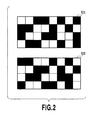
- Fig. 2 is a diagram showing an example of a mask pattern used in a multi-pass print for completing a printing by two times of scans (hereinafter, also called "pass") in the serial system.
- black areas each show a pixel ("1") permitting printing of a dot
- white areas each show a pixel ("0") not permitting printing of a dot
- number 501 denotes a mask pattern used in a scan of first pass
- number 502 denotes a mask pattern used in a scan of second pass.
- the pattern 501 and the pattern 502 are complementary with each other in regard to print permitting pixels (or print non-permitting pixels), and therefore, dots constituting an image to be completed are formed in any one of the first pass and second pass.
- a logical product is carried out for each pixel between image data to be completed and the above patterns and thus the result becomes binary data according to which respective printing elements actually executes printing in each pass.
- Japanese Patent Laid-Open No. H07-052390(1995 ) describes a method of producing a mask pattern in which print permitting pixels and print non-permitting pixels are arranged at a random.
- the print data can be expected to be distributed substantially equally to the plural scans and the plural printing element lines even in the print data of any image.
- Japanese Patent Laid-Open No. H06-191041 (1994 ) describes a method in which the fixed mask pattern as shown in Fig. 2 is not used, but print data ("1") of plural pixels to be printed continuously in a main scan direction or in a sub scan direction are distributed to be printed in different scans as many as possible.
- Fig. 3 is diagrams showing an arrangement of print pixels of binary image data and the result in which the print pixels are distributed to two scans according to the method described in Japanese Patent Laid-Open No. H06-191041(1994 ).
- the dots continuous in a main scan direction and in a sub scan direction are distributed equally to different scans.
- a plane of dots (one circle) printed in the precedent scan and a plane of dots (double circle) printed in the subsequent scan are shifted by an amount corresponding to one pixel from each other in any one of a main scan direction and a sub scan direction.
- the dots (one circle) printed in the precedent scan and the dots (double circle) printed in the subsequent scan completely overlap to generate white areas on the print medium, and the white areas lower the density of image.
- the shift is not as large as one pixel, the fluctuations in the distance between the neighboring dots and the overlapped portion have a large impact on a coverage of dots to the white areas of the print medium, finally on the image density.
- the shift between the planes changes with the fluctuation in the distance between the print medium and the ejection opening surface (the distance from a sheet) or the fluctuation in the conveying amount of the print medium, the density of the uniform image also changes with these fluctuations, which results in being recognized as density unevenness.
- Japanese Patent Laid-Open No. 2000-103088 describes a method of producing print data for enhancing the above robustness. More specifically, this producing method has paid attention on a fact that the fluctuation in the image density due to the print position shift is, as described in detail in Fig. 3 , caused by that binary print data distributed to plural times of scans or plural nozzle lines are completely complementary with each other. For reducing the extent of the above complementarity, the distribution of the image data to the plural times of the scans or the plural nozzle lines is carried out in a state of multi-valued data before binarizing and the multi-valued data after distributed are independently binarized.
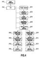
- Fig. 4 is a block diagram showing a control configuration example for realizing data distribution described in Japanese Patent Laid-Open No. 2000-103088 .
- This figure shows an example of distributing print data to two print heads (two nozzle lines).
- Multi-valued image data received from a host computer 2001 are subject to various kinds of image processing (2004 to 2006), and thereafter, a multi value SMS section 2007 generates data for a first print head and data for a second print head based on the data that has been subjected to the various kinds of image processing.
- Specially the same multi-valued image data to which the image processing has been executed are prepared as the data for the first print head and the data for the second print head.
- a distribution coefficient of 0.55 is used to the data for the first print head and a distribution coefficient of 0.45 is used to the data for the second print head to execute the conversion processing.
- the content of binarization processing to be executed later can be made different between the data for the first print head and the data for the second print head.
- overlaps of dots by the first print head and dots by the second print head finally formed can be generated in a certain ratio.
- Japanese Patent Laid-Open NO. 2000-103088 describes, in addition to an example where the distribution coefficient varies between the data for the first print head and the data for the second print head, an example where an error diffusion matrix used in error diffusion processing as binarization processing or threshold values in the error diffusion matrix varies.
- the multivalued data converted as above are transferred to a first binarization processing section 2010 and a second binarization processing section 2011.
- the binarization processing is executed by an error diffusion method using an error diffusion matrix and threshold values, and the binarized image data are stored respectively in a first band memory 2012 and in a second band memory 2013.
- the first and second print heads eject ink according to the binary data stored in the respective band memories to perform printing.
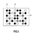
- Fig. 5 is a diagram showing an arrangement of dots on the print medium which are printed according to the aforementioned processing described in Japanese Patent Laid-Open No. 2000-103088 .
- a black circle 21 shows a dot printed by the first print head
- a white circle 22 shows a dot printed by the second print head
- a circle 23 shown in a hatched line shows a dot printed in an overlapped manner by the first print head and the second print head.
- a plane of dots printed in the first print head and a plane of dots printed in the second print head are shifted by an amount corresponding to one pixel from each other in any one of a main scan direction or a sub scan direction.
- dots printed in an overlapped manner by both the first print head and the second print head are newly increased, but there exist also dots where the dot composed of two dots which are already printed in the overlapped manner is separated. Accordingly, when the determination is made based upon an area having a certain breadth, the coverage of the dots to the white area does not change so much, therefore not inviting a change of the image density.
- the overlap of the dots is generated in a certain rate while basically eliminating complementarity or exclusiveness of dot formation by different scans or different print heads.
- Japanese Patent Laid-Open No. 2006-231736 describes the print data generation similar to that in Japanese Patent Laid-Open No. 2000-103088 . Specifically, in the same way as Japanese Patent Laid-Open No. 2000-103088 , the distribution coefficients are made different between the plural scans or between the plural printing element lines at the time of distributing the multi-valued image data to the plural scans or the plural printing element lines. In Japanese Patent Laid-Open No. 2006-231736 , the distribution coefficient varies in accordance with pixel positions.
- the distribution coefficients of two print heads vary in a linear way, in a periodical way, in a sinusoidal wave way, and in a combined wave way of a high frequency and a low frequency to the pixel position in a main scan direction, thereby restricting banding or color unevenness in the multi-pass printing.
- a printing apparatus which has properties of high-quality and multi-color and further, a relatively wide printing width of 60 inches, for example, and further, high speeding of the print speed is in progress.
- the multi-color and the printing to a large scale of sheet, however, there occurs the problem that the image processing is complicated and a circuit scale or a memory capacity increases in proportion to the number of colors or print width and also the cost increases.
- high speed of the printing speed increases a load of the image processing and also increases costs.
- the present invention provides an image processing apparatus, a printing apparatus, and an image processing method which enables generation of print data with reducing a processing load as much as possible and capable of enhancing robustness.
- the present invention in a first aspect provides an image processing apparatus as specified in claims 1 to 6.
- the present invention in a second aspect provides a printing apparatus as specified in claims 7 to 9.
- the present invention in a third aspect provides an image processing method as specified in claim 10.
- division and gradation lowering of an image are carried out not only by a first processing effective in robustness but also by a second processing, in accordance with channel information specifying the image.
- Fig. 1 is a perspective view showing the construction of an inkjet printing apparatus using a full line type print head according to a third embodiment of the present invention
- Fig. 2 is a diagram showing an example of a mask pattern used in a multi-pass print for completing a print by twice scans in a serial print system;
- Fig. 3 is diagrams showing an arrangement of print pixels in binary image data according to the conventional example and the result obtained by distributing the print pixels to twice scans according to the method described in Japanese Patent Laid-Open No. H06-191041(1994 );
- Fig. 4 is a block diagram showing a control construction example for realizing data distribution described in Japanese Patent Laid-Open No. 2000-103088 ;
- Fig. 5 is a diagram showing an arrangement of dots printed on a print medium according to the aforementioned processing described in Japanese Patent Laid-Open No. 2000-103088 ;
- Fig. 6 is a perspective view explaining a schematic construction of a serial type inkjet printing apparatus used in a first embodiment of the present invention
- Fig. 7 is a block diagram showing the control construction in the inkjet printing apparatus shown in Fig. 6 ;
- Fig. 8 is a block diagram showing mainly a detailed construction in an image processing section 603 shown in Fig. 7 ;
- Fig. 9 is a flow chart showing selection processing by a channel selection section 803 shown in Fig. 8 ;
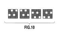
- Fig. 10 is a diagram showing an example of four patterns complementary with each other;
- Fig. 11 is a flow chart showing the processing executed by a channel selection section 803 according to a second embodiment of the present invention.
- Fig. 12 is a flow chart showing the processing executed by a channel selection section according to a modification in the second embodiment of the present invention.
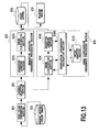
- Fig. 13 is a block diagram explaining a function of an image processing section 603 according to a third embodiment of the present invention.
- Figs. 14A and 14B are diagrams each showing a filter calculation, wherein 14A shows coefficients in the filter calculation and 14B shows the calculation result;
- Fig. 15 is diagrams showing the output result (binary data before filtering) of a gradation lowering section 8042 in the third embodiment and the result (data after filtering) after the above filtering processing is executed to this output result.
- Fig. 6 is a perspective view explaining a schematic structure of a serial type inkjet printing apparatus used in a first embodiment of the present invention.
- a print head 105 is mounted on a carriage 104 that moves at a constant speed in a main scan direction and ejects ink according to print data in a frequency corresponding to the constant speed.
- a conveying roller 704 and an auxiliary roller 703 rotate and a print medium P held between these rollers and between a feeding roller 705 and an auxiliary roller 706 is conveyed in a sub scan direction by an amount corresponding to a print width by the print head 105.
- This scan and the conveying operation are intermittently repeated to print an image on the print medium P step by step.
- the print head 105 includes print heads of black (K), cyan (C), magenta (M) and yellow (Y) which are located in a main scan direction shown in the figure and plurality of ejection openings are arranged in a sub scan direction in the print heads of the respective colors.
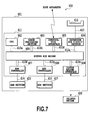
- Fig. 7 is a block diagram showing the control configuration in the aforementioned inkjet printing apparatus.
- a printer 600 is generally configured of a controller 601 and a printer engine 618.
- the controller 601 receives a print instruction and image data for printing from a host computer such as a personal computer and converts the received image data into binary data of a printable form at the printer engine 618 and outputs the binary data.
- the controller 601 is provided with a CPU 602, an image processing section 603, a printer engine interface section 604, a communication interface section 605, an expansion bus circuit section 606, a RAM controller 607, and a ROM controller 608. Further, each of these sections is connected through respective bus lines 610a to 610g to a system bus bridge 609.
- these sections are realized as an image formation controller ASIC (Application Specified Integrated Circuit) 611 enclosed by one package as a system LSI.
- the controller 601 is constructed to include an expansion slot 612 to which a function expansion unit is mounted, a RAM section 615 and a ROM section 617, and besides, a control section (not shown), a display section, a power circuit section and the like.
- the CPU 602 controls the entire controller 601, and reads out and executes programs such as the control procedure stored in the ROM section 617 or the RAM section 615. For example, controlling the image processing section 603 is performed for converting image data received from the host apparatus into print data as binary data. In addition, the CPU 602 performs control of the communication interface section 605, interpretation of communication protocol, control of the printer engine interface section 604 for transferring print data generated by the image processing section 603 to the printer engine 618, and the like.
- the image processing section 603 is configured to convert image data received from the host apparatus into print data printable in the printer engine 618 and the detailed configuration for the conversion will be explained in Fig. 8 and the subsequent figures.
- the printer engine interface section 604 is a section of transmitting and receiving data between the controller 601 and the printer engine 618. Specifically, the printer engine interface section 604 has a DMAC (direct memory access controller). In consequence, binary data generated by the image processing section 603 and stored in the RAM section 615 are read out through the RAM controller 607 sequentially and can be transferred to the printer engine 618.
- DMAC direct memory access controller
- the communication interface section 605 transmits and receives data to and from a host apparatus such as a personal computer or a work station and stores image data received from the host apparatus in the RAM section 615 through the RAM controller 607.
- a communication system of the communication interface section 605 may adopt any system of high-speed serial communication such as USB and IEEE 1394, parallel communication such as IEEE 1284 or network communication such as 100BASE-TX. In addition, a combination of these communication systems may be adopted. Further, not only wired communication systems, but also wireless communication systems may be adopted.
- the expansion bus circuit section 606 controls a function expansion unit mounted to an expansion slot 612. For example, the expansion bus circuit section 606 performs control of transmitting data through an expansion bus 613 to the function expansion unit and control of receiving data outputted from the function expansion unit.
- a communication unit for providing a communication function to the host apparatus such as USB, IEEE 1394, IEEE 1284 or network communication, a hard disc drive unit for providing a large capacity memory function or the like can be mounted to the expansion slot 612.
- the image processing section 603, the communication interface section 605, and the expansion bus circuit section 606 each have DMAC in the same way as the printer engine interface section 604 and can issue a memory access demand.
- the RAM controller 607 controls the RAM section 615 connected through the RAM bus 614 to the image formation controller ASIC 611.
- the RAM controller 607 relays data written in and read out between the CPU 602, each section having the DMAC, and the RAM section 615.
- the RAM controller 607 generates control signals necessary in accordance with a reading-out demand or a writing-in demand from the CPU 602 and the each section to realize the writing-in to the RAM section 615 or the reading-out from the RAM section 615.
- the ROM controller 608 controls the ROM section 617 connected through the ROM bus 616 to the image formation controller ASIC 611.
- the ROM controller 608 generates a control signal necessary in accordance with a reading-out demand from the CPU 602 to read out the control procedure or the data in advance stored in the ROM section 617 and transmits back the read content through the system bus bridge 609 to the CPU 602.
- the ROM controller 608 generates a necessary control signal to rewrite the content in the ROM section 617.
- the system bus bridge 609 is provided with a function connecting the respective sections constituting the image formation controller ASIC 611 and besides, adjusts the bus right in a case where access demands are issued from a plurality of sections simultaneously.
- the system bus bridge 609 can appropriately adjust the access demands according to a priority in advance assigned.
- the RAM section 615 is constructed of synchronous DRAM or the like and stores control procedure programs executed by the CPU 602 or temporarily stores image formation data generated at the image processing section 603 and provides a function such as a work memory of the CPU 602. In addition, the RAM section 615 performs temporary buffering of image data which the communication interface section 605 receives from the host apparatus and temporarily stores data from the function expansion unit connected through the expansion bus 613.
- the ROM section 617 is constructed of a flash memory or the like and stores parameters necessary for the control procedure and the printer control executed by the CPU 602.
- the flash memory is an electrically rewritable and nonvolatile device and can rewrite the control procedure and the parameters according to determined sequence.
- each circuit section is provided with a resister setting an operation mode or the like and the CPU 602 can set an operation mode or the like of each circuit section through a resister access bus (not shown).
- the printer engine 618 is, as in the case of the major construction shown in Fig. 6 , a print mechanism for printing an image on a print medium based upon binary data transmitted from the controller 601.
- Fig. 8 is a block diagram showing mainly a detailed configuration of the image processing section 603 shown in Fig. 7 .
- the received image data are stored in the memory buffer 801.
- the image data are formed of multi-valued data of red (R), green (G), and blue (B) which are expressed by 256 gradations of 8 bits per one pixel, for example.
- the data stored in the memory buffer 801 are transferred to a CMYK color conversion section 802 one pixel by one pixel in a predetermined timing to be converted into image data having a density value of multi value (256 gradations of 8 bits) corresponding to colors of ink used in the printing apparatus. This brings generation of print data used in each of two times of scans in a multi-pass printing which completes a print on the same area with two times of scans in the inkjet printing apparatus shown in Fig. 6 .
- the channel selection section 803 selects whether the subsequent processing to the image data is executed by image distribution precedence processing (first processing) or by gradation lowering precedence processing (second processing), in accordance with channel information of the image data. That is, the channel selection section 803 sends the image data to the image distribution precedence processing section 804 or the gradation lowering precedence processing section 805 in accordance with the selection result of the channel selection section.
- the "channel" means information for identifying image data and the information is distinguished by a color of ink or an ink ejection amount used in a printing in the present embodiment.
- the colors of inks used in printing are composed of black (K), cyan (C), magenta (M) and yellow (Y) and the image data is defined for each ink color
- four channels exist.
- the channel can be distinguished by the ejection amount.
- the distinction by the ink color is combined to the distinction of the ejection amount, the channel number is total of twelve as four colors x three kinds.
- an example distinguished by the ink color will be explained.
- Fig. 9 is a flow chart showing the selection processing by the channel selection section 803.
- the channel selection section 803 first determines at step S 701 whether or not a channel of the image data for which the selection is executed is a channel of the ink color that is previously set. When it is determined that the channel of the image data for the selection is the channel of the set ink color, the process goes to step S702, wherein the image data are transferred to the image distribution precedence processing section 804. On the other hand, when it is determined that the channel of the image data for the selection is not the channel of the set ink color, the process goes to step S703, wherein the image data are transferred to the gradation lowering precedence processing section 805.
- the setting of the ink color for the channel is as follows. Although it depends on matters composing the ink, for example, in printing with the color of ink having high density or low brightness, if printing positions of dots are shifted, a change in density of an image to be printed easily becomes large. Therefore, in the present embodiment, regarding channels of C, M and K inks showing relatively high density or low brightness among ink of C, M, K, and Y, the image distribution precedence processing section 804 of higher robustness is selected.
- the gradation lowering precedence processing section 805 is selected.
- the gradation lowering precedence processing section 805 is selected.
- multi-valued image data transferred to the gradation lowering precedence processing section 805 is subjected to gradation lowering (quantizing) processing by a gradation lowering section 8051 (second gradation lowering means).
- the multi-valued image data are converted into binary data. That is, data of 256 gradation values of 8 bits are subjected to the gradation lowering processing to be data of 2 gradation values of 1 bit.
- the binary print data are distributed or divided to image data of two planes corresponding to two scans of the print head for completing the printing, by the image distribution section 8052 (second distribution means).
- the aforementioned gradation lowering processing may use a quantization method such as an error diffusion process or a dither process generally known.
- the image distribution method of the image distribution section 8052 is also not limited in particular.
- the mask pattern as shown in Fig. 2 may be used or the random mask pattern described in Japanese Patent Laid-Open No. H07-052390(1995 ) may be used. Further, random series or random regular may be used. Further, as described in Japanese Patent Laid-Open No. H06-191041 (1994 ), it may be determined for each pixel to which plane the print pixel should be distributed while confirming the plane for printing the print pixels continuous in a main scan direction or in a sub scan direction.
- the multi-valued image data transferred to the image distribution precedence processing section 804 are first divided into image data of two planes (first divided image and second divided image) corresponding to two scans of the print head for completing the printing, by the image distribution section 8041 (first distribution means).
- an event of dividing multi-valued image data into plural planes is also called an event of distributing the multi-valued image data to the plural planes.
- This distribution can be performed by a distribution method described in Japanese Patent Laid-Open No. 2000-103088 or Japanese Patent Laid-Open No. 2006-231736 described before, for example, by a method of making the distribution coefficient different between planes for giving certain robustness to an image to be printed.
- the multi-valued image data distributed as described above are subject to gradation lowering processing in each plane by the gradation lowering section 8042 (first gradation lowering means).
- the method of the gradation lowering in use may adopt an error diffusion process or a dither process generally known.
- the multi-valued image data are equally distributed (to equal distribution coefficient) at the above distribution processing and at the process of the gradation lowering, as described in Japanese Patent Laid-Open No. 2000-103088 , the threshold value in the error diffusion or the content of the error diffusion itself may be made different between the planes to give the robustness to the print data.
- the print data of the two planes subjected to gradation lowering process by any of the image distribution precedence processing section 804 or the gradation lowering precedence processing section 805 are once stored in the print buffer 806 corresponding to each plane. Thereafter, ink is ejected from the print head in the printer engine 618 based on the print data stored in each print buffer 806 for performing the printing.
- the image distribution precedence processing section 804 for which the robustness is considered, for all the channels can restrict an increase in the processing load due to executing the gradation lowering processing after the distribution processing to each of the plural divided images. More specifically, since the gradation lowering processing is executed to one image data for each divided image in the image distribution precedence processing, the processing performance or the processing load needed in the image processing system is increased. On the other hand, since the gradation lowering processing of one time may be executed to one image data in the gradation lowering precedence processing, the processing performance or the processing load needed in the image processing system is lower in the gradation lowering precedence processing.
- the image distribution precedence processing is executed only to data of the color of ink identified as in the case of the present embodiment, making it possible to reduce the performance or the load required for the image processing system. According to the image processing method of the present embodiment thus, the printing of a uniform image excellent in robustness can be performed while restricting the load in the image processing system.
- the example explained above relates to the multi-pass print of two-pass, but the present invention can be applied also to the print by more multi-pass numbers.
- the multi-valued image for example, 256 values
- the image distribution section 8052 in the gradation lowering precedence processing section 805 the image data which has been subjected to the gradation lowering processing by using four mask patterns having a complementary relation with each other as shown in Fig. 10 can be distributed to four planes, for example.
- a second embodiment of the present invention relates to the processing of image data of channels distinguished based on an ink ejection amount and executes the processing similar to the process shown in the image processing shown in Fig. 8 in the printing apparatus shown in Fig. 6 of the above first embodiment.
- Fig. 11 is a flow chart showing the processing executed by the channel selection section 803 in the present embodiment.
- the channel selection section 803 determines at step S901 whether or not a channel of the image data for which the selection is executed is a channel of the ink ejection amount that is previously set.
- three kinds of ink ejection amounts of 1p1, 1.5p1 and 2p1 are possible.
- the processing in the image processing section 603 generates the print data for each print head.
- the channel selection section 803 makes determination using the channel of the ink ejection amount of 2p1 as a criterion among the three kinds of the ejection amounts.
- step S901 When it is determined at step S901 that the channel of the image data is the channel of the set ink ejection amount of 2p1, the process goes to step S902, wherein the image data for selection are transferred to the image distribution precedence processing section 804.
- step S901 when it is determined at step S901 that the channel of the image data is not the channel of the set ink ejection amount, that is, when it is determined that the channel of the image data is a channel of the ejection amount of 1p1 or 1.5p1, the process goes to step S903, wherein the image data for selection are transferred to the gradation lowering precedence processing section 805.
- the image distribution precedence processing excellent in robustness is selected.
- the image distribution precedence processing is thus executed only to the image data of the set ink ejection amount, thereby making it possible to output a uniform image excellent in robustness while reducing the load in the image processing system.
- the ink ejection amount to be set is one ejection amount of 2p1, but plural ejection amounts may be set, and by defining a channel of the ink ejection amount set in accordance with a combination of the ink color, the above effect can be further increased.
- any of the image distribution precedence processing and the gradation lowering precedence processing may be selected for the plurality of channels of processing image data depending on a combination of the ink color and the ink ejection amount.
- the color of ink is determined (S1001). When it is determined that the dolor of ink is the set color of ink (YES), the process moves to step S1003.
- step S1001 determines NO and the result of determination of the ejection amount (S1002) is a set ejection amount (YES)
- the process moves to step S1004.
- steps S1003 processes for image data of C and M inks moves to step S1003.
- a process for image data of Y ink is controlled to move to step S1004 in the case that the ejection amount is 2 pl.
- Processes for image data of Y ink which corresponds to the ejection amounts of 1 pl and 1.5 pl are controlled to move to step S1005.
- the determination of color of ink and the determination of ejection amount are combined to select the process properly.
- processes to be executed for the combination of a color of ink and an ejection amount may be previously selected to generate a table and the process to be executed may be determined based on the table of the color of ink and the ejection amount.
- a third embodiment of the present invention relates to a printing apparatus using a full line type print head in which two print heads perform the print operation similar to the multi-pass printing.
- Fig. 1 shows the general construction of a full line type inkjet printing apparatus according to the present embodiment.
- the print medium P receives a sheet fed by the feeding roller 705 and the auxiliary roller 706, the print medium P is conveyed in the direction of the feeding roller 704 and the auxiliary roller 703 and is conveyed in a sub scan direction at a predetermined speed while being held by the two pairs of the rollers.
- Ink is ejected onto the print medium to be thus conveyed from respective ejection openings of the print head 105 arranged in a main scan direction, at a certain frequency corresponding to the conveying speed of the print medium.
- the print head 105 includes the full line type print heads for ejecting ink of cyan (C), magenta (M), yellow (Y) and black (K) which are arranged to form two lines of the print heads for each color at a certain interval in a sub scan direction.
- the image data of each of K, C, M and Y are distributed to two planes (data of the divided images) corresponding to the two print heads of each color, and in a line of pixels connected in a sub-scan direction, dots are formed with ink ejected from ejection openings of the two print heads for each color.
- Fig. 13 is a block diagram for explaining a function of the image processing section 603 according to the present embodiment.
- the configuration other than the image distribution precedence processing section 809 is the same as the aforementioned embodiment.
- the channel selection section transfers the image data of each of C, M and K to the image distribution precedence processing section 809 and transfers the image data of Y to the gradation lowering precedence processing section 805.
- the image distribution precedence processing section 809 of the present embodiment makes the robustness of the image for which printing is completed by two print heads of each color of C, M and K more appropriate.
- the image distribution precedence processing section 809 of the present embodiment will be explained.
- the multi-valued image data transferred from the channel selection section 803 to the image distribution precedence processing section 809 are distributed to two planes by the image distribution section 8041.
- a correction value which a restriction information calculation section 8044 generates based on print quantity data stored in the print quantity buffer is, as described in Fig. 14 and the subsequent figures, added to multi valued (256 values) data of the second plane.
- the image distribution section 8041 corrects the multi-valued data by adding the correction value as described later and thereby, a certain complementary relation can be brought between the binary data obtained by quantizing the corrected multi-valued data and binary data of the other plane.
- the multi-valued data are sent to the gradation lowering section 8042 without the correction processing.
- the processing result of the first plane at the gradation lowering section 8042 is sent to the print buffer 806, as well as the print quantity buffer 8043 to be stored therein as the print quantity.
- the distribution itself in the image distribution section 8041 is equally made to the two planes in the present embodiment (the distribution coefficient is 0.5 in any plane). It should be noted that the distribution coefficient is not limited thereto, but as described in Japanese Patent Laid-Open No. 2000-103088 , the distribution coefficient may be made different between the planes or as described in Japanese Patent Laid-Open No. 2006-231736 , the distribution coefficient may be made different according to the pixel position.
- the gradation lowering section 8042 executes binarization processing by the error diffusion process for each plane of each color. More specifically, the gradation lowering section 8042 of the present embodiment executes the processing of converting the multi-valued image having 256 gradation values of eight bits into binary data of the lower gradation value as 2 gradation values of one bit. It should be noted that the gradation value lowered data obtained by the gradation lowering processing is not limited to the binary data without mentioning.
- the multi-valued image may be converted into so-called index data of 16 gradation values of four bits.
- the index data correspond to a dot arrangement pattern of the number of dots corresponding to the gradation value and the arrangement of the dots to be printed is defined by fixing the index data.
- a method of the gradation lowering is not limited to the error diffusion process, but the other binarization process such as a dither process may be employed.
- the print data of C, M and K binarized by the gradation lowering section 8042 are sent to the print buffer 806.
- the restriction information calculation section 8044 generates and updates the restriction information for the print data of the first plane for each of C, M, K stored in the print quantity buffer 8043. Specifically, the restriction information calculation section 8044 performs a filter calculation (filtering) to the binary data of the first plane of each color obtained from the print quantity buffer.
- Fig. 14A and 14B are diagrams showing a filter calculation, wherein Fig. 14A shows coefficients of the filter calculation and Fig. 14B shows the calculation result.
- a pixel shown in a hatched line is an object pixel defined as a processing object by the gradation lowering section 8042 and the restriction information calculation section 8044 distributes the result of the binarization to the peripheral pixels based on a coefficient of each pixel shown in Fig. 14A .
- the result of the binarization is "1" (dot print)
- the result obtained by multiplying 256 by the coefficient of each pixel is defined as a value of each pixel.
- the result obtained by multiplying 0 by the coefficient of each pixel is defined as a value of each pixel.
- the pixel corresponding to the object pixel is the largest and the next largest value is distributed to pixels positioned at the upward and downward sides and at the right and left sides of the object pixel.
- Fig. 15 is diagrams showing the output result (binary data before filtering) of the gradation lowering section 8042 and the result (data after filtering) after executing the filtering processing to the output result.
- a solid image having relatively low density is binarized and as a result the binary data "1" (dot print) exists in each of pixels existing away by a constant interval vertically and horizontally (binary data before filtering).
- the each pixel of the binary data is made be the object pixel and distributed to the peripheral pixels to obtain an arrangement of multi valued (256 values) data in which a value of the pixel corresponding to the object pixel is maximum.
- a difference is taken for each pixel between the multi-valued data after filtering obtained as the above and the multi-valued data (data outputted from the image distribution section 8041 to the gradation lowering section 8042) before being subject to gradation lowering processing (binarization) at the gradation lowering section 8042. Thereby, print quantity information of the plane as the processing object at this time is generated.
- Density is preserved between the multi-valued data (brightness values of 0 to 255 of red (R), green (G), and blue (B)) outputted from the image distribution section 8041 and the multi-valued data (brightness values of 0 to 255 of red (R), green (G), and blue (B)) converted from the data binarized at the gradation lowering section 8042. More specifically, even if the difference exists in a pixel unit, the density (here, brightness value of red (R), green (G) and blue (B) as the average pixel value) in a case of averaging the values of pixels of entire plane is reserved. Therefore, the difference in density between both the multi-valued data in the entire plane is 0.
- the difference taken between the multi-valued data after the filtering and the multi-valued data before the quantizing becomes 0 as the whole plane.
- the difference between the multi-valued data after the filtering and the multi-valued data before the quantizing can be a value other than 0 in the pixel unit, the difference has a tendency to be large in a pixel which is determined to print dot also after binarization (pixel where the binary data is "1").
- the restriction information calculation section 8044 subtracts the multi-valued data before the binarization from the multi-valued data after filtering to generate the restriction information.
- the generated restriction information for the plane of processing object is added to the restriction information generated at the plane so far and this added result is updated as the restriction information. It should be noted that in the processing to the two planes corresponding to two print heads of each color in the present embodiment, the restriction information is simply generated based on the binary data of the first plane.
- the image data distribution processing only is executed for the image data of the first plane among the image data obtained through the channel selection section 803. This distribution processing is executed to obtain about half of the value of multi-valued data of each color. That is, the distribution coefficient is set to 0.5 to obtain the multi-valued image data of the first plane.
- the processing similar to the image data distribution processing for the first plane described above is first executed for each color. That is, the multi-valued image data after the distributing, which is half of the value of the multi-valued data for each color, is obtained. Next, a value of the restriction information obtained in regard to the first plane is converted to be a minus value and the minus value of the restriction information is added to the multi-valued image data as the correction value for each corresponding pixel.
- the binary data of the pixel defined as "1" (dot print) in the quantization result of the multi-valued data for the first plane is a value which is not 0 in the generation processing of the restriction information in regard to the object pixel and the peripheral pixels.
- this restriction information is added as a minus value to the multi-valued data of the second plane.
- the pixel of the second plane the value of which is made small by the above addition, probability of becoming a binary data of "1" (dot print) in the quantization (gradation lowering) by the gradation lowering section 8042 is lower depending on the extent of the value made small. More specifically, in an arrangement of the dots printed according to the binary data of the first plane and the second plane, it is possible to control a ratio in which the dots by the first plane and the dots by the second plane are overlapped to be formed, according to the aforementioned filter calculation. As a result, the ratio of the dots formed in the overlapped manner can be restricted to be smaller as compared to the method described in Japanese Patent Laid-Open No. 2000-103088 .
- a size (filter size) of the area where the coefficients are arranged in the filter calculation also may affect the complementarity between the planes.
- the coefficients of the filter may be appropriately defined, for example, according to the content of the image to be printed, including an event that all the coefficients of the peripheral pixels other than the object pixel are made 0.
- the multi-valued data after the filtering may be stored in the print quantity buffer 8043 as the restriction information with no change.
- the result found by subtracting the restriction information of the first plane from the image data (distribution coefficient 1.0) before distribution at the image distribution section 8041 is used as the image data of the second plane after the distribution. This is because the restriction information is obtained by subtracting the multi-valued data found by multiplying the image data before the distribution by the distribution coefficients of the first plane, from the multi-valued data after filtering.
- the image distribution section 8041 converts the restriction information obtained in regard to the first plane to a minus value and adds the minus value to the multi-valued data found by multiplying the image data before the distribution by the distribution coefficients for the second plane, as the correction value for each corresponding pixel.
- the image distribution section 8041 adds the multi-valued data found by multiplying the image data before the distribution by the distribution coefficients for the first plane, to the multi-valued data found by multiplying the image data before the distribution by the distribution coefficients for the second planes.
- the multi-valued data after filtering obtained in regard to the first plane is subtracted.
- the image distribution section 8041 may only subtract the multi-valued data after filtering obtained at the first plane from the multi-valued data before the distribution in regard to the second plane.
- a ratio of the pixels where the dots formed by plural print heads or plural times of scans are overlapped to be printed can be restricted to be small.
- the gradation lowering of the first plane is executed by a method where the dots are arranged to disperse appropriately, thereby making it possible to appropriately disperse the dot arrangement of the plane where the result of the quantization is reflected.
- Appropriate dispersion of the dot arrangement means that a low frequency component in the space frequency measured in regard to the dot arrangement is low and can be realized by any of conventionally known methods.
- a texture due to the dot arrangement in the individual plane is confirmed and this texture is possibly recognized as a harmful effect of an image.
- the load in the image processing system can be reduced by selection in response to the channel by the channel selection section 803.
- a printing apparatus with multicolor and a wide print width of 60 inches is provided.
- the storage area of the print quantity buffer 8043 storing the print quantity is large in such a device, increasing the memory capacity and the cost. Therefore, in regard to the channel of the ink color in which the effect of the image distribution precedence processing is relatively small, the gradation lowering precedence processing which does not require the print quantity buffer 8043 is selected. Thereby, the print quantity buffer 804 can eliminate the capacity thereof by the corresponding quantity.
- the transfer area between the gradation lowering section 8042 and the print quantity buffer 8043 and the transfer area between the print quantity buffer 8043 and the restriction information calculation section 8044 can be also reduced.
- the uniform image excellent in robustness can be outputted while restricting the load of the image processing system.
- the image distribution section 8041 distributes the inputted multi-valued image data to M pieces of planes from the first plane to the M-th plane.
- the gradation lowering section 8042 sequentially integrates the results by executing the gradation lowering from the first plane to the (M -1) -th plane to predetermined pixel positions in the print quantity buffer 8043.
- the dot is difficult to be printed by the M-th print scan. That is, in all of the first plane (first print scan) to the M-th plane (M-th print scan), M kinds of gradation lowering signals corresponding to each of the M times of print scans are outputted so that dots are printed in such a manner as to be dispersed exclusively with each other.
- the application order of the print quantity buffer 8043 and the restriction information calculation section 8044 may be reversed. In this case, the restriction information calculation section 8044 sequentially integrates the results by executing the filtering processing from the first plane to the (M -1)-th plane to predetermined pixel positions in the print quantity buffer 8043.
- the filter used at the restriction information calculation section 8044 is, as shown in Fig. 14A , an isotropic weighted average filter having the area of 3 pixels x 3 pixels and in which the coefficients are arranged concentrically, but is not limited thereto.
- a wider square having an area of 5 pixels x 5 pixels or 7 pixels x 7 pixels may be used, but an an1sotropic filter having an area of 5 pixels x 7 pixels or 5 pixels x 9 pixels and in which filter coefficients are arranged elliptically may be used.
- the filter having band pass characteristics or bypass characteristics may be used instead of the form of the filter having the robustness.
- the present embodiment is, in the same way as the first embodiment, constructed so that the channel selection section 803 selects the subsequent processing in accordance with the set ink color among plural channels for processing the image data, but is not limited thereto.
- the subsequent processing may be selected in accordance with the set ink ejection amount as in the case of the second embodiment or the subsequent processing may be selected in accordance with the ink color and the ink ejection amount, the similar effect can be obtained.
- each of the first and second embodiments explains the serial type printing apparatus
- the third embodiment explains the full line type printing apparatus, but the processing methods of all the embodiments can be appropriately applied to the full line type or the serial type printing apparatus.
- the printing apparatus with the inkjet system is used, but the present invention is not limited to such a device. Any printing apparatus with a dot alignment system having plural printing elements for printing dots on the print medium and with a dot alignment system expressing an image by the arrangement of the dots can suitably adopt the present invention.
- the image processing apparatus executing the featuring image processing of the present invention is explained taking the printing apparatus having the image processing function as an example, but the present invention is not limited to such a construction.
- the present invention may be constructed so that the image processing is executed by the host apparatus and the print data after gradation lowering are input to the printing apparatus.
- the present invention may be constructed so that an image photographed by a digital camera or the like or a graphic image is directly input to a printing apparatus without through a host apparatus and all of the image processing including the processing explained in the above embodiments are executed by the printing apparatus.
- the host apparatus serves as the image processing apparatus in the present invention and in the latter case, the printing apparatus serves as the image processing apparatus in the present invention.
- aspects of the present invention can also be realized by a computer of a system or apparatus (or devices such as a CPU or MPU) that reads out and executes a program recorded on a memory device to perform the functions of the above-described embodiment(s), and by a method, the steps of which are performed by a computer of a system or apparatus by, for example, reading out and executing a program recorded on a memory device to perform the functions of the above-described embodiment(s).
- the program is provided to the computer for example via a network or from a recording medium of various types serving as the memory device (e.g., computer-readable medium).
Landscapes
- Engineering & Computer Science (AREA)
- Multimedia (AREA)
- Signal Processing (AREA)
- Ink Jet (AREA)
- Record Information Processing For Printing (AREA)
- Facsimile Image Signal Circuits (AREA)
Applications Claiming Priority (1)
| Application Number | Priority Date | Filing Date | Title |
|---|---|---|---|
| JP2008329966A JP5164826B2 (ja) | 2008-12-25 | 2008-12-25 | 画像処理装置および画像処理方法 |
Publications (2)
| Publication Number | Publication Date |
|---|---|
| EP2202955A2 true EP2202955A2 (fr) | 2010-06-30 |
| EP2202955A3 EP2202955A3 (fr) | 2010-12-22 |
Family
ID=42102879
Family Applications (1)
| Application Number | Title | Priority Date | Filing Date |
|---|---|---|---|
| EP09015905A Withdrawn EP2202955A3 (fr) | 2008-12-25 | 2009-12-22 | Appareil de traitement d'images, appareil d'impression et procédé de traitement d'images |
Country Status (4)
| Country | Link |
|---|---|
| US (1) | US8477397B2 (fr) |
| EP (1) | EP2202955A3 (fr) |
| JP (1) | JP5164826B2 (fr) |
| CN (1) | CN101866431B (fr) |
Families Citing this family (6)
| Publication number | Priority date | Publication date | Assignee | Title |
|---|---|---|---|---|
| CN101977772B (zh) * | 2008-01-22 | 2013-04-10 | 佳能株式会社 | 喷墨记录装置及喷墨记录方法 |
| JP5366561B2 (ja) | 2009-01-07 | 2013-12-11 | キヤノン株式会社 | 画像処理装置および画像処理方法 |
| JP5791242B2 (ja) | 2010-07-21 | 2015-10-07 | キヤノン株式会社 | インクジェット記録装置、インクジェット記録方法及びインクジェット記録ヘッド |
| US10052897B2 (en) | 2014-05-28 | 2018-08-21 | Hewlett-Packard Development Company, L.P. | Arranging image data segments in printing devices |
| JP6606389B2 (ja) | 2015-09-29 | 2019-11-13 | キヤノン株式会社 | 記録制御装置、記録装置、及びデータ処理方法 |
| CN109191429B (zh) * | 2018-07-26 | 2022-06-14 | 中国科学院福建物质结构研究所 | 一种基于机器视觉的3d打印喷嘴检测方法 |
Citations (1)
| Publication number | Priority date | Publication date | Assignee | Title |
|---|---|---|---|---|
| US20080137146A1 (en) | 2006-08-28 | 2008-06-12 | Canon Kabushiki Kaisha | Image data generating apparatus, image printing apparatus, and image data generating method |
Family Cites Families (16)
| Publication number | Priority date | Publication date | Assignee | Title |
|---|---|---|---|---|
| JP3229454B2 (ja) | 1992-10-16 | 2001-11-19 | キヤノン株式会社 | インクジェット記録方法およびインクジェット記録装置 |
| US6042212A (en) | 1993-06-30 | 2000-03-28 | Canon Kabushiki Kaisha | Ink-jet recording apparatus and method using asynchronous masks |
| JP3176182B2 (ja) | 1993-06-30 | 2001-06-11 | キヤノン株式会社 | 記録装置、インクジェット記録装置及び記録装置の制御方法 |
| US5818474A (en) | 1993-06-30 | 1998-10-06 | Canon Kabushiki Kaisha | Ink-jet recording apparatus and method using asynchronous masks |
| JP4620817B2 (ja) * | 1998-05-29 | 2011-01-26 | キヤノン株式会社 | 画像処理装置および画像処理方法 |
| JP3902898B2 (ja) * | 1999-11-29 | 2007-04-11 | キヤノン株式会社 | 画像形成方法、画像形成装置及び画像処理方法 |
| JP2001150701A (ja) * | 1999-11-29 | 2001-06-05 | Canon Inc | 画像形成装置、画像形成方法及び画像処理方法 |
| JP4560193B2 (ja) | 2000-09-29 | 2010-10-13 | キヤノン株式会社 | データ処理方法及びデータ処理装置 |
| DE60209421T2 (de) | 2001-11-06 | 2006-11-09 | Canon K.K. | Tintenstrahldruckvorrichtung und Korrekturverfahren für ein Bild |
| JP2004328160A (ja) * | 2003-04-22 | 2004-11-18 | Canon Inc | 画像形成装置及びその制御方法 |
| JP4574163B2 (ja) * | 2003-12-12 | 2010-11-04 | キヤノン株式会社 | インクジェット記録装置及びインクジェット記録方法 |
| JP2006231736A (ja) | 2005-02-25 | 2006-09-07 | Seiko Epson Corp | 画像処理装置、画像形成装置、画像処理方法およびプログラム |
| JP2006338269A (ja) * | 2005-06-01 | 2006-12-14 | Canon Inc | 記録システム、記録方法、記録装置、及びドライバ |
| US7506950B2 (en) | 2006-04-11 | 2009-03-24 | Canon Kabushiki Kaisha | Data processing apparatus, printing apparatus and method of creating mask pattern |
| KR101090060B1 (ko) * | 2006-11-14 | 2011-12-07 | 삼성전자주식회사 | 그레이 이미지의 보정이 가능한 화상형성장치 및화상형성방법 |
| JP4838704B2 (ja) * | 2006-12-27 | 2011-12-14 | キヤノン株式会社 | 画像形成装置およびその制御方法 |
-
2008
- 2008-12-25 JP JP2008329966A patent/JP5164826B2/ja not_active Expired - Fee Related
-
2009
- 2009-12-17 US US12/640,741 patent/US8477397B2/en not_active Expired - Fee Related
- 2009-12-22 EP EP09015905A patent/EP2202955A3/fr not_active Withdrawn
- 2009-12-25 CN CN200910247055.1A patent/CN101866431B/zh not_active Expired - Fee Related
Patent Citations (1)
| Publication number | Priority date | Publication date | Assignee | Title |
|---|---|---|---|---|
| US20080137146A1 (en) | 2006-08-28 | 2008-06-12 | Canon Kabushiki Kaisha | Image data generating apparatus, image printing apparatus, and image data generating method |
Also Published As
| Publication number | Publication date |
|---|---|
| EP2202955A3 (fr) | 2010-12-22 |
| CN101866431B (zh) | 2013-03-20 |
| US20100165390A1 (en) | 2010-07-01 |
| JP2010149385A (ja) | 2010-07-08 |
| JP5164826B2 (ja) | 2013-03-21 |
| US8477397B2 (en) | 2013-07-02 |
| CN101866431A (zh) | 2010-10-20 |
Similar Documents
| Publication | Publication Date | Title |
|---|---|---|
| JP5434015B2 (ja) | 印刷装置 | |
| US8743420B2 (en) | Image processor and image processing method | |
| US8462387B2 (en) | Image processing device, printing apparatus, and image processing method | |
| US8477397B2 (en) | Print data generating configuration that enables an image print to have a tolerance for image quality degradation against variations of print characteristics between printing elements of a print head | |
| US8896883B2 (en) | Image processing apparatus, printing apparatus, and image processing method | |
| JP2010076216A (ja) | 印刷装置および印刷方法 | |
| JP5127626B2 (ja) | 画像処理装置および画像処理方法 | |
| JP5994919B2 (ja) | 印刷装置、印刷方法、および、コンピュータープログラム | |
| JP2015143013A (ja) | インクジェット記録装置、インクジェット記録方法および画像処理装置 | |
| JP5521337B2 (ja) | 印刷装置、印刷方法、コンピュータープログラムおよび記録媒体 | |
| US20160173724A1 (en) | Printing apparatus, printing method, program, and image processing apparatus | |
| US9053407B2 (en) | Image processing apparatus and image processing method | |
| US8482800B2 (en) | Image processing apparatus and image processing method | |
| JP2009269240A (ja) | 画像形成装置及び画像形成方法 | |
| EP2207338A2 (fr) | Appareil de traitement d'images, appareil d'impression et procédé de traitement d'images | |
| JP5564771B2 (ja) | 印刷装置、印刷方法、コンピュータプログラム、記録媒体、印刷媒体、および、プリンタ | |
| US8488198B2 (en) | Image processing apparatus and image processing method | |
| JP5341420B2 (ja) | 画像処理装置及び画像処理方法 | |
| JP2013136250A (ja) | 印刷装置および印刷方法 | |
| JP2010081058A (ja) | 画像処理システムおよび画像処理方法 | |
| JP2010064326A (ja) | 印刷装置および印刷方法 |
Legal Events
| Date | Code | Title | Description |
|---|---|---|---|
| PUAI | Public reference made under article 153(3) epc to a published international application that has entered the european phase |
Free format text: ORIGINAL CODE: 0009012 |
|
| AK | Designated contracting states |
Kind code of ref document: A2 Designated state(s): AT BE BG CH CY CZ DE DK EE ES FI FR GB GR HR HU IE IS IT LI LT LU LV MC MK MT NL NO PL PT RO SE SI SK SM TR |
|
| AX | Request for extension of the european patent |
Extension state: AL BA RS |
|
| PUAL | Search report despatched |
Free format text: ORIGINAL CODE: 0009013 |
|
| AK | Designated contracting states |
Kind code of ref document: A3 Designated state(s): AT BE BG CH CY CZ DE DK EE ES FI FR GB GR HR HU IE IS IT LI LT LU LV MC MK MT NL NO PL PT RO SE SI SK SM TR |
|
| AX | Request for extension of the european patent |
Extension state: AL BA RS |
|
| 17P | Request for examination filed |
Effective date: 20110622 |
|
| 17Q | First examination report despatched |
Effective date: 20111222 |
|
| STAA | Information on the status of an ep patent application or granted ep patent |
Free format text: STATUS: THE APPLICATION IS DEEMED TO BE WITHDRAWN |
|
| 18D | Application deemed to be withdrawn |
Effective date: 20131112 |