EP2203000B1 - Correction adaptatif de gain de rétroaction - Google Patents
Correction adaptatif de gain de rétroaction Download PDFInfo
- Publication number
- EP2203000B1 EP2203000B1 EP09180287.6A EP09180287A EP2203000B1 EP 2203000 B1 EP2203000 B1 EP 2203000B1 EP 09180287 A EP09180287 A EP 09180287A EP 2203000 B1 EP2203000 B1 EP 2203000B1
- Authority
- EP
- European Patent Office
- Prior art keywords
- feedback
- hearing aid
- signal
- gain
- filter
- Prior art date
- Legal status (The legal status is an assumption and is not a legal conclusion. Google has not performed a legal analysis and makes no representation as to the accuracy of the status listed.)
- Active
Links
Images


Classifications
-
- H—ELECTRICITY
- H04—ELECTRIC COMMUNICATION TECHNIQUE
- H04R—LOUDSPEAKERS, MICROPHONES, GRAMOPHONE PICK-UPS OR LIKE ACOUSTIC ELECTROMECHANICAL TRANSDUCERS; ELECTRIC HEARING AIDS; PUBLIC ADDRESS SYSTEMS
- H04R25/00—Electric hearing aids
- H04R25/45—Prevention of acoustic reaction, i.e. acoustic oscillatory feedback
- H04R25/453—Prevention of acoustic reaction, i.e. acoustic oscillatory feedback electronically
-
- H—ELECTRICITY
- H04—ELECTRIC COMMUNICATION TECHNIQUE
- H04R—LOUDSPEAKERS, MICROPHONES, GRAMOPHONE PICK-UPS OR LIKE ACOUSTIC ELECTROMECHANICAL TRANSDUCERS; ELECTRIC HEARING AIDS; PUBLIC ADDRESS SYSTEMS
- H04R25/00—Electric hearing aids
- H04R25/30—Monitoring or testing of hearing aids, e.g. functioning, settings, battery power
- H04R25/305—Self-monitoring or self-testing
-
- H—ELECTRICITY
- H04—ELECTRIC COMMUNICATION TECHNIQUE
- H04R—LOUDSPEAKERS, MICROPHONES, GRAMOPHONE PICK-UPS OR LIKE ACOUSTIC ELECTROMECHANICAL TRANSDUCERS; ELECTRIC HEARING AIDS; PUBLIC ADDRESS SYSTEMS
- H04R25/00—Electric hearing aids
- H04R25/70—Adaptation of deaf aid to hearing loss, e.g. initial electronic fitting
Definitions
- the present invention relates to a method for performing adaptive feedback cancelation in a hearing aid.
- a hearing aid comprises an input transducer, an amplifier and a receiver unit.
- This whistling problem has been known for many years and in the standard literature on hearing aids it is commonly referred to as feedback, ringing, howling or oscillation.
- EP 1 439 736 A discloses a feedback cancellation unit in audio systems e.g. hearing aid.
- the feedback cancelation unit provided between an output of a hearing aid processor and an input of a subtractor includes an adaptive filter having filter coefficients and a slowly varying filter for providing constant factors along the physical feedback path. Based on the filter coefficient of the adaptive filter a maximum stable gain value is set up for the hearing aid processor.
- the unit provides rapid correction to the feedback path model when the hearing aid goes unstable by slowly tracking the perturbations such as chewing, sneezing or using a telephone hand set in the feedback path. It also reduces computational burden as adaptive gain value is updated instead of complete set of zero filter coefficients.
- Feedback thus limits the maximum stable gain that is achievable in a hearing aid.
- Some traditional approaches to avoid this feedback problem utilizes a feedback cancellation unit by which the feedback path is adaptively estimated and a feedback cancelling signal is generated and subtracted from the input signal to the hearing aid. Hereby as much as 10 dB additional gain is achievable before the onset of whistling.
- the gain of the feedback cancellation signal will either be too large, in which case the feedback is overcompensated to such an extent that the hearing aid gain will not be adequate, or too small, in which case the gain of the signal will exceed the maximum stable gain limit and whistling may occur.
- One object of the present invention is to provide a method with improved feedback cancellation.
- a first aspect of the present invention relates to a hearing aid comprising an input transducer for generating an audio signal, a feedback model configured for modelling a feedback path of the hearing aid, a subtractor for subtracting an output signal from the feedback model from the audio signal to form a compensated audio signal, a signal processor that is connected to an output of the subtractor for processing the compensated audio signal to perform hearing loss compensation, and a receiver that is connected to an output of the signal processor for converting the processed compensated audio signal into a sound signal.
- the hearing aid may be a multi-band hearing aid performing hearing loss compensation differently in different frequency bands, thus accounting for the frequency dependence of the hearing loss of the intended user.
- the audio signal from the input transducer is divided into two or more frequency channels or bands; and, typically, the audio signal is amplified differently in each frequency band.
- a compressor may be utilized to compress the dynamic range of the audio signal in accordance with the hearing loss of the intended user.
- the compressor performs compression differently in each of the frequency bands varying not only the compression ratio, but also the time constants associated with each band.
- the time constants refer to the attack and release time constants.
- the hearing aid may further comprise an adaptive feedback gain correction unit for gain adjustment in the processing of the compensated audio signal based on an estimate of the residual error of the output signal from the feedback model.
- the hearing aid may have attack and release filters configured for smoothing process parameters in the adaptive feedback gain correction unit.
- the feedback model may comprise an adaptive feedback cancellation filter.
- the estimate of the residual error may be based on the filter coefficients of the adaptive feedback cancellation filter.
- the estimate of the residual error may be based on monitoring of the output signal of the adaptive feedback cancellation filter.
- the estimate of the residual error could, in an alternative embodiment, be based on the signal power level of the output signal of the adaptive feedback cancellation filter.
- the residual error may be based on the filter coefficients of the adaptive feedback cancellation filter as well as on the signal power level of the output signal of the adaptive feedback cancellation filter
- the gain adjustment may be performed separate from hearing loss compensation.
- the signal processor may be configured to perform multi-band hearing loss compensation in a set of frequency bands.
- the estimate of the residual error may then be based on an estimate A k of the residual error in each of the frequency bands k.
- the feedback model e.g. an adaptive filter, adapting to changes in the feedback path may be a broad band model, i.e. the model operates substantially in the entire frequency range of the hearing aid, or in a significant part of the frequency range of the hearing aid without being divided into a set of frequency bands, and thus, the estimate of the residual error may be based on an estimate of an adaptive broad-band contribution ⁇ to the estimate.
- the feedback model may be divided into a set of frequency bands for individual modelling of the feedback path in each frequency band.
- the estimate of the residual error may be based on an estimate of an adaptive contribution ⁇ m to the estimate in each frequency band m of the feedback model.
- the frequency bands m of the feedback model and the frequency bands k of the hearing loss compensation may be identical, but preferably, they are different, and preferably the number of frequency bands m of the feedback model is less than the number of frequency bands of the hearing loss compensation.
- a second aspect of the present invention relates to a method in a hearing aid comprising an input transducer for generating an audio signal, a feedback model configured for modelling a feedback path of the hearing aid, a subtractor for subtracting an output signal from the feedback model from the audio signal to form a compensated audio signal, a signal processor that is connected to an output of the subtractor for processing the compensated audio signal to perform hearing loss compensation, and a receiver that is connected to an output of the signal processor for converting the processed compensated audio signal into a sound signal.
- the method may further comprise the steps of estimating the residual error of the feedback path modelling performed by the feedback model, and adjusting a gain of the compensated audio signal based on the estimate.
- the feedback model may comprise an adaptive feedback cancellation filter, and in this case the method may further comprise the steps of monitoring the filter coefficients of the adaptive feedback cancellation filter, and estimating the residual error based on the monitoring.
- the step of gain adjustment may be performed before performing hearing loss compensation.
- the present invention relates to a hearing aid according to claim 1.
- the present invention relates to a method according to claim 12.
- the adjustment of the gain parameter of the signal processor may be determined bandwise in a plurality of frequency bands or determined in a broad band, and may be performed bandwise in a plurality of frequency bands.
- the adjustment of the gain parameter of the signal processor may be determined band-wise in a plurality of frequency bands or determined in a broad band, and may be performed in a broad band.
- the feedback cancellation may be performed by subtracting an estimated feedback signal from the incoming signal.
- the signal processor may be configured to perform noise reduction and/or loudness restoration.
- An embodiment of a hearing aid comprises an input transducer, an amplifier and a receiver unit.
- a transducer is a unit that is able to transform energy from one form to another form.
- the input transducer is a microphone, which is a unit that may transform an acoustical signal into an electrical signal.
- it is a telecoil, which may transform the energy of a magnetic field into an electrical signal.
- the input transducer comprises both a microphone and a telecoil, and may also comprise a switching system by which it is possible to switch between the microphone and telecoil input. During use, a part of the sound emitted from the receiver is received at the microphone.
- the electromagnetic field generated by the coils of the receiver may reach the telecoil and add to the electromagnetic or magnetic field to be picked up by the telecoil.
- This sound and electromagnetic field emitted by the receiver and received by the input transducers are called feedback. It is undesirable as this may lead to re-amplification of certain frequencies and become unpleasant for the wearer of the hearing aid. Therefore a feedback cancellation unit may be included in the hearing aid.
- the input transducer may be a microphone or the like. It is not only audible sound that may cause feedback; also vibrations in the hearing aid housing may cause feedback.
- the present invention provides Adaptive Feedback Gain Correction (AFGC) in order to reduce or eliminate the residual error of the feedback model.
- AFGC Adaptive Feedback Gain Correction
- an estimate of the model error has to be provided.
- This estimate of the model error may be combined with a previously determined maximum stable gain limit to provide an adequate gain correction which maintains stability and may ideally restore normal loudness.
- a hearing aid performs hearing loss compensation differently in different frequency bands, thus accounting for the frequency dependence of the hearing loss of the intended user.
- Such a multi-channel or multi-band hearing aid divides the audio signal from the input transducer, e.g. one or more microphones, a telecoil, etc., into two or more frequency channels or bands; and, typically, amplifies the audio signal in each frequency band differently.
- a compressor may be utilized to compress the dynamic range of the audio signal in accordance with the hearing loss of the intended user.
- the compressor performs compression differently in each of the frequency bands varying not only the compression ratio, but also the time constants associated with each band.
- the time constants refer to the attack and release time constants.
- the attack time is the time required for the compressor to react and lower the gain at the onset of a loud sound.
- the release time is the time required for the compressor to react and increase the gain after the cessation of the loud sound.
- the estimate of the model error may be combined with previously determined maximum stable gain limits in each frequency band to provide an adequate gain correction which maintains stability and may ideally restore normal loudness.
- Fig. 1 schematically illustrates feedback in general in a hearing aid 10.
- the external signal is an acoustical signal that is received by the microphone 12 that converts the acoustical signal into an audio signal that is input to the signal processor 14.
- the audio signal is amplified in accordance with the hearing loss of the user.
- the signal processor 14 may for example comprise a multi-band compressor.
- the output signal from the signal processor 14 is converted to an acoustical signal by the receiver 16 that directs the acoustical signal towards the eardrum of the user when the hearing aid is worn properly by the user.
- the acoustical signal from the receiver 16 cannot be completely prevented from also propagating to the microphone 12 as indicated by feedback path 22 in Fig. 1 .
- the phenomenon that the signal 18 leaks back from the receiver 16 to the input transducer 12 is called feedback. At low amplification feedback only introduces harmless colouring of the sound. However, when the hearing aid gain is large and the amplified signal propagating back from the receiver 16 to the input transducer 12 starts to exceed the level of the original signal, the feedback loop gets unstable which results in audible distortions and squealing.
- Fig. 2 schematically shows a block-diagram of a conventional hearing aid 10 with a feedback model 15.
- the feedback model 15 models the feedback path 22, i.e. the feedback model seeks to generate a signal that is identical to the signal propagated along the feedback path 22.
- the feedback model 15 is typically an adaptive digital filter 15 which adapts to changes in the feedback path 22.
- the hearing aid 10 further comprises a microphone 12 for receiving incoming sound and converting it into an audio signal.
- the audio signal is processed in the signal processor 14 to compensate for the hearing loss of the user of the hearing aid 10.
- a receiver 16 converts the output of the signal processor 14 into sound.
- the signal processor 14 may comprise various signal processing elements, such as amplifiers, compressors and noise reduction systems, etc.
- the feedback model 15 generates a compensation signal to the subtracting unit 17 in order to suppress or cancel the feedback signal 24, whereby feedback along the feedback path 22 is suppressed or cancelled before processing takes place in the signal processor 14.
- An external feedback path 22 is shown as a dashed line 18, 24 between the receiver 16 and the microphone 12.
- the external feedback path 22 makes it possible for the microphone 12 to pick up sound from the receiver 16 which may lead to well known feedback problems, such as whistling.
- the internal feedback path may comprise an acoustical connection, a mechanical connection or a combination of both acoustical and mechanical connection between the receiver 16 and the microphone 12 within the housing of the hearing aid 10.
- Fig. 2 may be simplified by assuming linearity of all analogue components and merging their contribution into one feedback path, which leads to Fig. 3 .
- Fig. 3 schematically illustrates signal paths of a hearing aid 10.
- An audio signal 26 is generated by an input transducer and processed as illustrated in Fig. 3 in order to provide a hearing impairment corrected output signal z to be presented to a user.
- the audio signal 26 is added to the feedback signal 24 that leaks back to the input transducer (not shown) via the feedback path 22.
- the feedback signal 24 is compensated or suppressed by subtraction of the model signal 28 of the feedback model 15 in the subtracting unit 17.
- the feedback model 15 may comprise a feedback compensation filter.
- E z 2 E ⁇ G 1 - GR 2 ⁇ E x 2
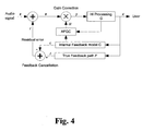
- Fig. 4 illustrates the signal processing of a hearing aid comprising an input transducer (not shown) for generating an audio signal x, and a feedback model C, preferably an adaptive feedback cancellation filter, configured for modelling the feedback path F of the hearing aid thereby generating the signal c.
- the signal f is the feedback signal that has propagated back to the input transducer along feedback path F and has also been converted by the input transducer. Still further, a signal processor is connected to an output of the subtractor for processing the compensated audio signal e to perform hearing loss compensation, and a receiver (not shown) that is connected to an output of the signal processor for converting the processed compensated audio signal z into a sound signal directed towards the ear drum of the user when the hearing aid is properly worn by the user.
- the hearing aid further comprises an adaptive feedback gain correction unit AFGC for gain adjustment ⁇ of the compensated audio signal e.
- the gain adjustment ⁇ is determined from an estimate of the residual error r of the feedback path modelling performed by the feedback model C.
- the gain adjustment ⁇ is based on the gains applied in the signal processor and parameters of the feedback model C, e.g. the filter coefficients of an adaptive feedback cancellation filter of the feedback model C.
- the gain adjustment is performed separate from and before hearing loss compensation performed in the signal processor.
- other signal processing circuitry than the AFGC can be designed and used in a conventional way.
- the fitting software used to adjust knee-points and compression ratios and time constants of a multi-band compressor in the signal processor in order to fit the hearing aid to the hearing loss of the intended user is typically rather complex to develop.
- such fitting software need not be changed in order to incorporate the AFGC.
- the signal processor of Fig. 4 operates on a signal y that matches the loudness of the desired part of the audio signal generated from the desired acoustical signal whereby the hearing loss compensation, e.g. the loudness restoration, will be perceived to be based on the signal of interest.
- the gain adjustment may be performed at other positions in the signal path, for example after the signal processor, but then the other parts of the processing must cope with the residual error r of the feedback model C.
- a gain adjustment ⁇ k is preferably determined for each frequency band of the hearing aid.
- the signal x is the audio signal provided by the input transducer (not shown), the signal r is the residual error signal also provided by the input transducer (not shown), and f is the true feedback signal.
- the expectation operator will be omitted in the following and the variance will be used instead (this is valid since all signals have a mean value of zero).
- AFGC adaptive feedback gain correction
- FIG. 5 schematically illustrates a hearing aid with a compressor that performs dynamic range compression using digital frequency warping.
- a hearing aid is disclosed in more detail in WO 03/015468 , in particular the basic operating principles of the warped compressor are illustrated in Fig. 10 and the corresponding parts of the description of WO 03/015468 .
- the hearing aid according to the present invention illustrated in Fig. 5 corresponds to the hearing aid of Fig. 10 of WO 03/015468 ; however feedback cancellation and AFGC and noise reduction have been added to the signal processing circuitry of the hearing aid. Other processing circuitry may be added as well.
- the invention may also be used with advantage in a multi-band hearing aid in which the frequency bands are not warped.
- the hearing aid schematically illustrated in Fig. 5 has a single microphone 12. However, the hearing aid may comprise two or more microphones, possibly with a beamformer. These components are not shown for simplicity. Similarly, possible A/D and D/A converters, buffer structures, optional additional channels, etc. are not shown for simplicity.
- the incoming signal received by the microphone 12 is passed through a DC filter 32 which ensures that the signals have a mean value of zero; this is convenient for calculating the statistics as discussed previously.
- the signal received by the microphone 12 may be passed directly to the subtractor 17.
- the feedback cancellation may be applied by subtracting an estimated feedback signal c from the audio signal x.
- the feedback signal estimate is calculated by the digital feedback suppression (DFS) subsystem 15 comprising a chain of fixed filter 37 and adaptive filter 41 operating on the (delayed) output signal z of the hearing aid.
- the fixed filter(s) 37 is typically an all-pole or general infinite impulse response (IIR) filter initialized at a certain point in time, for example upon turn on in the ear of the hearing aid, or, in a fitting situation.
- the adaptive filter 41 is preferably a finite impulse response (FIR) filter, but in principle any other adaptive filter structure (lattice, adaptive IIR, etc.) may be used.
- the adaptive filter 41 is an all zero filter.
- the DFS is a broad-band system, i.e. the DFS operates in the entire frequency range of the multi-band hearing aid.
- the DFS may also be divided into a number of frequency bands with individual feedback cancellation in each DFS frequency band.
- the signal processor frequency bands and the DFS frequency bands may be identical, but typically, they are different, and preferably, the DFS has a fewer number of frequency bands than the signal processor performing loudness restoration.
- the output signal c of the DFS subsystem 15 is subtracted from the audio signal x and transformed to the frequency domain. As explained in more detail in WO 03/015468 , in particular in Fig.
- the hearing aid illustrated in Fig. 5 has a side-branch structure where the analysis of the signal is done outside the signal path; the signal shaping is done using a time domain-filter constructed from the output of the side-branch.
- a warped side-branch system has advantages for high quality low-delay signal processing, but in principle any textbook FFT-system, a multi-rate filter bank, or a non-warped side-branch system may be used. Thus, although it is convenient to use frequency warping, it is not at all necessary in order to exercise the invention.
- the analysis of the signal starts by constructing a warped Fast Fourier Transform (FFT) which provides a signal power estimate for each warped frequency band.
- FFT Fast Fourier Transform
- the warping is obtained in the FIR filter 43 by replacing the unit delays in the FIR filter's 43 tapped delay line by all pass filters.
- a chain of so-called gain agents analyze these power estimates and adjust the gains and the corresponding powers in each band in a specific order.
- the order shown here is Adaptive Feedback Gain Correction (AFGC) 45, Noise reduction 47, and Loudness restoration 49.
- AFGC Adaptive Feedback Gain Correction
- Noise reduction 47 Noise reduction
- Loudness restoration 49 may use other combinations or sequences.
- the first gain agent, AFGC 45 obtains input from the DFS subsystem 15, as indicated by arrow 53, which provides an estimate of the relative error of the feedback model. Also, the gain vector in the frequency domain output by loudness restoration block 49 as calculated in the previous iteration (representing the current gains as applied by the warped FIR filter 43) is input to the AFGC 45, as is illustrated by the arrow 55. The AFGC 45 then combines these inputs with its own feedback reference gain settings (the prior knowledge, e.g. obtained from initialization by measuring or estimating the feedback path during a fitting situation) to calculate an adequate gain adjustment. Determination of the gain adjustment is described in more detail below.
- the second gain agent 47 shown here, providing noise reduction, is optional.
- Noise reduction is a comfort feature which is often used in modern hearing aids.
- the first two gain agents attempt to shape the signal in such a way that it is optimally presented for any listener, regardless of hearing loss, i.e., it is attempted to restore the envelope of the original signal without unwanted noise or feedback.
- the remaining gain agent(s) 49 adjust loudness in order to compensate for the user-dependent hearing loss.
- a significant difference should be noted between restoring the loudness of the original signal without feedback, as done by the AFGC unit 45, and restoring normal loudness perception for the hearing impaired listener, as performed by the loudness restoration block 49.
- the latter typically requires significant amplification (which causes the need for a feedback suppression system) and is often combined with multi-band compression and limiting strategies (to provide more amplification to soft signals than to loud signals).
- the agents 45, 47 and 49 in the gain-chain may be re-ordered, e.g., by putting AFGC agent 45 at the end of the chain.
- the output 55 that is constituted by an output gain vector in the frequency domain, which contains the combined contributions of each individual gain agent in each frequency band, is transformed back to the time domain using an Inverse Fast Fourier Transform (IFFT) 57 to be used as coefficient vector for the warped FIR filter.
- IFFT Inverse Fast Fourier Transform
- the gain vector is also propagated back to the AFGC unit 45 to be used in the next gain adjustment determination as illustrated by arrow 55.
- the signal that has passed through the warped FIR filter 43 is output limited in an output limiter 59 to ensure that (possibly unknown) receiver 16 and/or microphone 12 non-linearity does not influence the feedback path too much. Otherwise the DFS system 15 may fail to model extreme signal levels adequately.
- separate output limiting is optional because it may for example already be provided by a dynamic range compressor or by limits in the fixed point precision of a digital signal processor (DSP).
- DSP digital signal processor
- ⁇ g k provides the target for the gain corrections in dB, i.e. a target for the gain adjustment.
- the symbol ⁇ g k is used instead of the linear form ⁇ k because gains in the side branch are normally calculated in the log domain.
- r u (in dB).
- r u will be updated recursively from the actual hearing aid gains as available at the output of the gain-chain, i.e. the output of loudness restoration block 49, including the contribution of all gain agents, previous gain corrections, and the feedback reference gains.
- the attack and release filters are applied in two stages.
- a DFS feature ⁇ which is used for all bands, is smoothed with configurable attack and release rates.
- an instantaneous attack is combined with a slow fixed-step release.
- a calibration procedure may provide two maximum stable gain MSG curves, namely MSG on and MSG off .
- the MSG off curve is the inverse of the feedback gain curve, as measured by the initialization procedure.
- the MSG on curve also known as the error curve, is the inverse of the difference between the modelled and the measured feedback gain curves.
- the internal path is simply the model fitted to the impulse response obtained by a calibration procedure. In order to avoid standing waves the measurement of the impulse response of the feedback path is preferably done by using a MLS signal. Other signals can be used as well, e.g. band-limited white noise.
- the external path is defined by the raw impulse response obtained at initialization for which the magnitude response is identical to the inverse MSG off curve.
- the third path may be obtained from the MSG on curve. Normally the MSG on curve is significantly above the MSG off curve because of the added stable gain, so to use it as a reference, this offset may be taken into account.
- the curves have to be transformed to the warped frequency domain, which may be done in two different ways.
- a suitable windowing function is first used to window with the magnitude response for each warp band.
- the frequency bands are preferably overlapping in order to account for loss of signal features at band boundaries due to the attenuation done by the window function.
- the maximum gain (the worst case frequency) is taken, or the contribution of all bins is merged using Parseval's theorem, i.e. summing the normalized squared values in the linear domain.
- the reference vector may be assumed to result from the true feedback path, and the difference between the reference coefficients and the adaptive filter coefficients may be performed by a separate FIR filter. Then the output power of this hypothetical filter provides an upper bound on the residual error.
- the adaptive filter coefficients adapt away from the reference for a good reason, and that this does not lead to a one-to-one increase in the residual error. Consequently, it may be assumed that only a fraction of the deviation from the reference contributes to the residual error.
- ⁇ max ⁇ ⁇ min , c ⁇ ⁇ h * w - w ref ⁇ ⁇ norm
- ⁇ min the minimal fractional residual error
- h a filter for emphasizing certain frequencies
- c a tuning parameter
- ⁇ norm is a constant for normalization (which for a final implementation may also be included in c) calculated using the same norm.
- ⁇ norm ⁇ h * w ref ) ⁇
- the parameter ⁇ min is closely related to the static performance of the feedback canceller, it may be linked to the headroom estimate provided by calibration procedure.
- the parameter c is closely related to the dynamic performance of the feedback canceller and therefore has to be tuned by trial and error.
- a good choice for h appears to be the first order difference filter which removes DC, emphasizes the high frequencies and may be calculated without multiplications.
- the output signal of the adaptive feedback cancellation filter is monitored, and the residual error is estimated based on the monitoring of the output signal.
- the estimate of the residual error could, in an alternative embodiment, be based on the signal, e.g. the signal power level, of the output signal of the adaptive feedback cancellation filter.
- the residual error may be based on the filter coefficients of the adaptive feedback cancellation filter as well as on the signal power level of the output signal of the adaptive feedback cancellation filter
- the present invention relates to a hearing aid comprising a signal processor, an input transducer electrically connected to the signal processor, a receiver electrically connected to the signal processor, and an adaptive feedback cancellation filter configured to suppress feedback from a signal path from the receiver to the input transducer, the hearing aid further comprising:
- adjusting a gain parameter, (e.g. the gain) of the signal processor will provide an efficient cancellation or suppression of the feedback signal while at the same time providing optimum loudness for the user.
- the gain parameter of the signal processor is a feed-forward gain of the signal processor, and not the gain of the feedback cancellation signal, the later being influenced by the filter coefficients of the feedback cancellation filter.
- a simple way of adjusting the gain parameter is achieved, because the gain of the input signal is scaled before it is subjected to the possibly nonlinear signal processing in the signal processor in order to provide a hearing impairment corrected signal.
- the input signal will thus have the optimal loudness before it is subjected to the hearing impairment specific processing by the signal processor, and hence the hearing impairment corrected signal will have the optimal loudness when it will be presented to the user.
- the adjustment of the gain parameter may further be based on a set of reference coefficients, for example the filter coefficients of an adaptive digital filter modelling the feedback path.
- the reference coefficients could be established by measurements during a fitting situation and/or by estimation based on previous adjustments.
- the adjustment of the gain parameter may further be based on the deviation of the filter coefficients of the feedback cancellation filter from a reference set of filter coefficients. This deviation could be established as the numerical difference between the filter coefficients and the reference values or as a fraction of the numerical difference between the actual filter coefficients and the reference set of filter coefficients.
- the coefficients of the adaptive feedback cancellation filter may be determined from the previous sample or block of samples. New or adapted coefficients of the adaptive feedback cancellation filter may be determined for the current sample or block of samples, and may be based on signal properties of the current sample or block of samples.
- the hearing aid may further comprise attack and release filters configured for smoothing process parameters in the gain correction unit. This is contemplated to allow a faster processing.
- a second aspect of the present invention relates to a method of adjusting a gain parameter of a signal processor of a hearing aid
- the method may comprise the steps of monitoring the filter coefficients of a feedback cancellation filter of the hearing aid, and adjusting a gain parameter of the signal processor in dependence of the monitored filter coefficients.
- the monitored filter coefficients may be determined from a previous sample or block of samples, e.g. the immediately preceding sample or block of samples.
- the adjustment of the gain parameter of the signal processor may comprise a gain adjustment of an input signal to the signal processor.
- the adjustment of the gain parameter of the signal processor may further be based on a set of reference filter coefficients.
- the adjustment of the gain parameter may further be based on the deviation of the filter coefficients of the feedback cancellation filter from a reference set of filter coefficients.
- the adjustment of the gain parameter of the signal processor may be determined band-wise in a plurality of frequency bands or determined in a broad band, and is performed band-wise in a plurality of frequency bands.
- the adjustment of the gain parameter of the signal processor may be determined band-wise in a plurality of frequency bands or determined in a broad band, and may be performed in a broad band.
- the broad band is a frequency band that comprises the plurality of frequency bands, and in a preferred embodiment the plurality of frequency bands are overlapping.
- the overlapping is configured such that the bands are consecutively ordered after centre frequency and that one band overlaps the next band at the band boundaries.
- the feedback cancellation may be performed by subtracting an estimated feedback signal from the incoming signal. This is contemplated to suppress or reduce the feedback.
- the signal processor may be configured to perform noise reduction and/or loudness restoration. This is contemplated to allow presentation of a comfortable sound signal to a user or wearer of the hearing aid.
- Fig. 6 schematically illustrates a hearing aid comprising an input transducer 36 configured to receive an external sound signal.
- the input transducer 36 may comprise a microphone and a telecoil. Alternatively the input transducer 36 may comprise a microphone.
- the hearing aid further comprises a feedback cancellation unit 38.
- the hearing aid still further comprises a signal processor 40.
- the hearing aid further comprises a receiver 42.
- the receiver 42 is configured to emit or transmit sound processed by the signal processor 40. Some of the sound transmitted or emitted from the receiver 42 may leak back to the input transducer 36, as illustrated by the arrow 44. Thereby the external sound signal may, as described above, be mixed with the sound leaking back from the receiver 42.
- the illustrated configuration of the feedback cancellation unit 38 is a so called feedback path configuration generally known in the art, wherein the feedback cancellation unit produces a feedback signal that is subtracted from the input signal provided by the input transducer 36 in the adder 54.
- the feedback cancellation unit 38 could be placed in a feed forward signal path.
- the feedback cancellation unit 38 may comprise a memory unit to hold one or more previous samples to be used in feedback cancellation. Furthermore, as illustrated by the arrow 58 from the feedback cancellation unit 38 to the signal processor 40, information about the actual filter coefficients of the feedback cancellation filter are used to adjust a gain parameter, e.g. the gain itself, of the signal processor 40. Thus, it is seen that information about the actual filter coefficients of the feedback cancellation filter 38 is used to adjust the feed-forward gain, e.g. amplification, of the hearing aid.
- a gain parameter e.g. the gain itself
- the gain of the signal processor 40 may be adjusted in dependence of how much the actual filter coefficients of the feedback cancellation filter 38 deviates from a reference set of filter coefficients, wherein the reference set of filter coefficients for example may have been generated from a measurement of the feedback path during fitting of the hearing aid, for example in a dispenser's office.
- Fig. 7 schematically illustrates a method comprising providing a hearing aid 46.
- the hearing aid comprising a signal processor, an input transducer electrically connected to the signal processor, a receiver electrically connected to the signal processor, and an adaptive feedback cancellation filter configured to suppress feedback from a signal path from the receiver to the input transducer and a feedback gain correction unit configured for gain adjustment of an input signal to the signal processor.
- the method comprising the steps of recording 48 a sample, e.g. comprising a block of signal samples, of a sound signal received via the input transducer. Determining 50 gain adjustments based on the sample or block of samples and previous coefficients of the adaptive feedback cancellation filter. Applying 52 the gain adjustment before hearing impairment compensation.
- Fig. 8 schematically illustrates a preferred embodiment of a method of adjusting a gain parameter of a hearing aid.
- the method comprises a step 63 of monitoring the filter coefficients of a feedback cancellation filter of the hearing aid, a step 65 of comparing the monitored filter coefficients to a reference set of filter coefficients, and a step 67 of adjusting the gain parameter of the hearing aid in dependence of said comparison.
- the step of comparing the filter coefficients to a set of reference filter coefficients may comprise the determination of a difference, e.g. the numerical difference between the actual filter coefficients and the reference set of filter coefficients.
Landscapes
- Health & Medical Sciences (AREA)
- General Health & Medical Sciences (AREA)
- Neurosurgery (AREA)
- Otolaryngology (AREA)
- Physics & Mathematics (AREA)
- Engineering & Computer Science (AREA)
- Acoustics & Sound (AREA)
- Signal Processing (AREA)
- Circuit For Audible Band Transducer (AREA)
Claims (14)
- Prothèse auditive (10) comprenant
un transducteur d'entrée pour produire un signal audio,
un modèle de rétroaction configuré pour modéliser un chemin de rétroaction de la prothèse auditive,
un soustracteur pour soustraire un signal de sortie du modèle de rétroaction provenant du signal audio pour former un signal audio compensé,
un processeur de signal qui est relié à une sortie du soustracteur pour traiter le signal audio compensé pour effectuer une compensation de perte d'audition en appliquant le gain de prothèse auditive G, et
un récepteur qui est relié à une sortie du processeur de signal pour transformer le signal audio compensé traité en un signal sonore, caractérisée en ce que
la prothèse auditive comprenant en outre :une unité de correction adaptative de gain de rétroaction pour appliquer un ajustement de gain α au signal audio compensé en se basant sur une évaluation R de l'erreur résiduelle du signal de sortie C à partir du modèle de rétroaction, dans laquelle
- Prothèse auditive selon la revendication 1, dans laquelle le modèle de rétroaction comprend un filtre adaptatif d'annulation de rétroaction.
- Prothèse auditive selon la revendication 2, dans laquelle l'évaluation de l'erreur résiduelle est basée sur le signal de sortie provenant du filtre adaptatif d'annulation de rétroaction.
- Prothèse auditive selon la revendication 2, dans laquelle l'évaluation de l'erreur résiduelle est basée sur les coefficients de filtre du filtre adaptatif d'annulation de rétroaction.
- Prothèse auditive selon n'importe laquelle des revendications précédentes, dans laquelle l'ajustement de gain est effectué séparément de la compensation de perte d'audition.
- Prothèse auditive selon n'importe laquelle des revendications précédentes, dans laquelle le processeur de signal est configuré pour effectuer une compensation de perte d'audition multibande dans un ensemble de bandes de fréquence, et dans laquelle l'évaluation de l'erreur résiduelle est basée sur une évaluation A k de l'erreur résiduelle dans chacune des bandes de fréquence k.
- Prothèse auditive selon la revendication 6, dans laquelle l'ajustement de gain ak est calculé à partir de :

dans laquelle
l'erreur résiduelle Rk dans chacune des bandes de fréquence k est donnée par
dans laquelle
β est une erreur résiduelle fractionnaire adaptative pour toutes les bandes, et
A k est la contribution à l'erreur résiduelle dans chacune des bandes de fréquence k. - Prothèse auditive selon la revendication 7, dans laquelle A k est évaluée pendant l'initialisation du filtre adaptatif d'annulation de rétroaction.
- Prothèse auditive selon la revendication 7 ou 8 lorsque dépendante de la revendication 2, dans laquelle la détermination de β est basée sur les coefficients de filtre du filtre adaptatif d'annulation de rétroaction.
- Prothèse auditive selon la revendication 9, dans laquelle β est calculée à partir de :

dans laquelle
β min représente une valeur minimale de β,
h représente un filtre pour souligner certaines fréquences,
c est un paramètre de réglage,
βnorm, est une constante pour normalisation βnorm = ∥h * wref, ∥
w est le vecteur de coefficient du filtre adaptatif d'annulation de rétroaction, et
wref est le vecteur de coefficient de référence du filtre adaptatif d'annulation de rétroaction obtenu pendant l'initialisation du filtre. - Prothèse auditive selon n'importe laquelle des revendications précédentes, comprenant en outre des filtres d'attaque et de libération configurés pour lisser des paramètres de processus dans l'unité de correction de gain.
- Procédé dans une prothèse auditive comprenant un transducteur d'entrée pour produire un signal audio,
un modèle de rétroaction configuré pour modéliser un chemin de rétroaction de la prothèse auditive,
un soustracteur pour soustraire un signal de sortie du modèle de rétroaction provenant du signal audio pour former un signal audio compensé,
un processeur de signal qui est relié à une sortie du soustracteur pour traiter le signal audio compensé pour effectuer une compensation de perte d'audition en appliquant le gain de prothèse auditive G, et
un récepteur qui est relié à une sortie du processeur de signal pour transformer le signal audio compensé traité en un signal sonore,
le procédé comprenant les étapes consistant à
évaluer l'erreur résiduelle R de la modélisation de chemin de rétroaction effectuée par le modèle de rétroaction, et
appliquer un ajustement de gain α au signal audio compensé en se basant sur l'évaluation,
dans laquelle
- Procédé selon la revendication 12, dans lequel le modèle de rétroaction comprend un filtre adaptatif d'annulation de rétroaction, et comprenant en outre les étapes de contrôle du signal de sortie du filtre adaptatif d'annulation de rétroaction, et d'évaluation de l'erreur résiduelle en se basant sur le contrôle.
- Procédé selon la revendication 12, dans lequel le modèle de rétroaction comprend un filtre adaptatif d'annulation de rétroaction, et comprenant en outre les étapes de contrôle des coefficients de filtre du filtre adaptatif d'annulation de rétroaction, et d'évaluation de l'erreur résiduelle en se basant sur le contrôle.
Applications Claiming Priority (1)
| Application Number | Priority Date | Filing Date | Title |
|---|---|---|---|
| DKPA200801839 | 2008-12-23 |
Publications (2)
| Publication Number | Publication Date |
|---|---|
| EP2203000A1 EP2203000A1 (fr) | 2010-06-30 |
| EP2203000B1 true EP2203000B1 (fr) | 2015-12-02 |
Family
ID=41020817
Family Applications (1)
| Application Number | Title | Priority Date | Filing Date |
|---|---|---|---|
| EP09180287.6A Active EP2203000B1 (fr) | 2008-12-23 | 2009-12-22 | Correction adaptatif de gain de rétroaction |
Country Status (4)
| Country | Link |
|---|---|
| US (1) | US10602282B2 (fr) |
| EP (1) | EP2203000B1 (fr) |
| CN (1) | CN101808265B (fr) |
| DK (1) | DK2203000T3 (fr) |
Families Citing this family (35)
| Publication number | Priority date | Publication date | Assignee | Title |
|---|---|---|---|---|
| CN105103462A (zh) * | 2012-12-11 | 2015-11-25 | 南加利福尼亚大学 | 用于双工器和共存无线通信系统的无源泄露抵消网络 |
| US9635479B2 (en) * | 2013-03-15 | 2017-04-25 | Cochlear Limited | Hearing prosthesis fitting incorporating feedback determination |
| US20140364681A1 (en) | 2013-06-05 | 2014-12-11 | Martin Hillbratt | Prosthesis state and feedback path based parameter management |
| US9148734B2 (en) * | 2013-06-05 | 2015-09-29 | Cochlear Limited | Feedback path evaluation implemented with limited signal processing |
| US9712908B2 (en) * | 2013-11-05 | 2017-07-18 | Gn Hearing A/S | Adaptive residual feedback suppression |
| EP2869600B1 (fr) | 2013-11-05 | 2016-12-28 | GN Resound A/S | Suppression adaptative de rétroaction résiduelle |
| WO2015089091A1 (fr) | 2013-12-10 | 2015-06-18 | University Of Southern California | Amélioration de l'isolation et de l'adaptation d'impédance dans des réseaux de suppression hybrides et des duplexeurs |
| WO2015123668A1 (fr) | 2014-02-14 | 2015-08-20 | University Of Southern California | Annulation à base d'hybrides en présence d'une désadaptation d'antenne |
| WO2015123586A1 (fr) | 2014-02-14 | 2015-08-20 | University Of Southern California | Filtres de réflexion et de réflexion hybride |
| US9871543B2 (en) | 2014-02-19 | 2018-01-16 | University Of Southern California | Miniature acoustic resonator-based filters and duplexers with cancellation methodology |
| DE102014215165A1 (de) * | 2014-08-01 | 2016-02-18 | Sivantos Pte. Ltd. | Verfahren und Vorrichtung zur Rückkopplungsunterdrückung |
| DE102014218672B3 (de) | 2014-09-17 | 2016-03-10 | Sivantos Pte. Ltd. | Verfahren und Vorrichtung zur Rückkopplungsunterdrückung |
| US10105539B2 (en) | 2014-12-17 | 2018-10-23 | Cochlear Limited | Configuring a stimulation unit of a hearing device |
| US9774960B2 (en) * | 2014-12-22 | 2017-09-26 | Gn Hearing A/S | Diffuse noise listening |
| US10581650B2 (en) | 2015-09-08 | 2020-03-03 | Qorvo Us, Inc. | Enhancing isolation in radio frequency multiplexers |
| US9762416B2 (en) | 2015-09-08 | 2017-09-12 | Abtum Inc. | Reflection coefficient reader |
| US9866201B2 (en) | 2015-09-08 | 2018-01-09 | Abtum Inc. | All-acoustic duplexers using directional couplers |
| US9912326B2 (en) | 2015-09-08 | 2018-03-06 | Abtum Inc. | Method for tuning feed-forward canceller |
| US9755668B2 (en) | 2015-09-30 | 2017-09-05 | Abtum Inc. | Radio frequency complex reflection coefficient reader |
| US10038458B2 (en) | 2015-10-06 | 2018-07-31 | Abtum Inc. | Reflection-based radio-frequency multiplexers |
| KR102527018B1 (ko) | 2015-10-12 | 2023-04-27 | 압툼 인크. | 하이브리드 커플러 기반 무선 주파수 멀티플렉서 |
| CN107509151A (zh) * | 2016-06-14 | 2017-12-22 | 中兴通讯股份有限公司 | 一种放大音频信号的方法及装置 |
| KR102419926B1 (ko) | 2016-09-21 | 2022-07-11 | 코르보 유에스, 인크. | 하이브리드 기반 무선 주파수 듀플렉서 및 멀티플렉서의 향상된 아이솔레이션 |
| US10110997B2 (en) | 2017-02-17 | 2018-10-23 | 2236008 Ontario, Inc. | System and method for feedback control for in-car communications |
| US9894452B1 (en) | 2017-02-24 | 2018-02-13 | Bose Corporation | Off-head detection of in-ear headset |
| US10681458B2 (en) | 2018-06-11 | 2020-06-09 | Cirrus Logic, Inc. | Techniques for howling detection |
| EP3703391B1 (fr) * | 2019-02-27 | 2025-11-26 | Oticon A/s | Dispositif auditif comprenant un limiteur de gain de boucle |
| WO2021055513A1 (fr) * | 2019-09-16 | 2021-03-25 | The Regents Of The University Of California | Atténuation de rétroaction acoustique dans des prothèses auditives avec déformation de fréquence par des réseaux passe-tout |
| US11184713B2 (en) | 2019-11-19 | 2021-11-23 | Sonova Ag | Systems and methods for adjusting a gain limit of a hearing device |
| CN111479204B (zh) * | 2020-04-14 | 2021-09-03 | 上海力声特医学科技有限公司 | 适用于人工耳蜗的增益调节方法 |
| KR102696750B1 (ko) | 2020-08-29 | 2024-08-21 | 썬전 샥 컴퍼니, 리미티드 | 진동전달함수를 얻기 위한 시스템들 및 방법들 |
| CN112327752A (zh) * | 2020-11-16 | 2021-02-05 | 大连理工大学 | 一种四轴车削加工轨迹轮廓误差双环补偿方法 |
| CN113362839B (zh) * | 2021-06-01 | 2024-10-01 | 平安科技(深圳)有限公司 | 音频数据处理方法、装置、计算机设备及存储介质 |
| CN114466297B (zh) * | 2021-12-17 | 2024-01-09 | 上海又为智能科技有限公司 | 一种具有改进的反馈抑制的听力辅助装置及抑制方法 |
| CN121418723B (zh) * | 2025-11-20 | 2026-04-24 | 北京怡同科技有限公司 | 一种智能话筒防啸叫控制方法、设备及介质 |
Family Cites Families (20)
| Publication number | Priority date | Publication date | Assignee | Title |
|---|---|---|---|---|
| US5259033A (en) | 1989-08-30 | 1993-11-02 | Gn Danavox As | Hearing aid having compensation for acoustic feedback |
| DK169958B1 (da) | 1992-10-20 | 1995-04-10 | Gn Danavox As | Høreapparat med kompensation for akustisk tilbagekobling |
| US6434246B1 (en) * | 1995-10-10 | 2002-08-13 | Gn Resound As | Apparatus and methods for combining audio compression and feedback cancellation in a hearing aid |
| US6219427B1 (en) | 1997-11-18 | 2001-04-17 | Gn Resound As | Feedback cancellation improvements |
| US6876751B1 (en) | 1998-09-30 | 2005-04-05 | House Ear Institute | Band-limited adaptive feedback canceller for hearing aids |
| US6757396B1 (en) * | 1998-11-16 | 2004-06-29 | Texas Instruments Incorporated | Digital audio dynamic range compressor and method |
| CA2372017A1 (fr) * | 1999-04-26 | 2000-11-02 | Dspfactory Ltd. | Correction physiologique d'une prothese auditive numerique |
| EP1191813A1 (fr) * | 2000-09-25 | 2002-03-27 | TOPHOLM & WESTERMANN APS | Prothèse auditive avec un filtre adaptatif pour la suppression de la réaction acoustique |
| EP1191814B2 (fr) | 2000-09-25 | 2015-07-29 | Widex A/S | Prothèse auditive multibande avec filtres adaptatifs multibandes pour la suppression de la rétroaction acoustique . |
| US6754356B1 (en) * | 2000-10-06 | 2004-06-22 | Gn Resound As | Two-stage adaptive feedback cancellation scheme for hearing instruments |
| US6831986B2 (en) * | 2000-12-21 | 2004-12-14 | Gn Resound A/S | Feedback cancellation in a hearing aid with reduced sensitivity to low-frequency tonal inputs |
| US7277554B2 (en) | 2001-08-08 | 2007-10-02 | Gn Resound North America Corporation | Dynamic range compression using digital frequency warping |
| AU2003236382B2 (en) * | 2003-08-20 | 2011-02-24 | Phonak Ag | Feedback suppression in sound signal processing using frequency transposition |
| US8116489B2 (en) * | 2004-10-01 | 2012-02-14 | Hearworks Pty Ltd | Accoustically transparent occlusion reduction system and method |
| WO2006063624A1 (fr) | 2004-12-16 | 2006-06-22 | Widex A/S | Audiophone avec estimation de gain modele d'effet larsen |
| EP1830602B1 (fr) | 2006-03-01 | 2019-07-31 | Sonova AG | Une méthode d'obtenir des arrangements d'un instrument d'audition, et un instrument d'audition |
| WO2008065209A2 (fr) | 2008-01-22 | 2008-06-05 | Phonak Ag | Procédé de détermination d'un gain maximal dans un dispositif auditif, et dispositif auditif |
| EP2136575B1 (fr) | 2008-06-20 | 2020-10-07 | Starkey Laboratories, Inc. | Système pour mesurer le gain stable maximum dans des dispositifs d'assistance auditive |
| EP2217007B1 (fr) | 2009-02-06 | 2014-06-11 | Oticon A/S | Prothèse auditive avec suppression adaptative de la rétroaction |
| US8355517B1 (en) | 2009-09-30 | 2013-01-15 | Intricon Corporation | Hearing aid circuit with feedback transition adjustment |
-
2009
- 2009-01-13 US US12/353,107 patent/US10602282B2/en active Active
- 2009-12-22 EP EP09180287.6A patent/EP2203000B1/fr active Active
- 2009-12-22 DK DK09180287.6T patent/DK2203000T3/da active
- 2009-12-23 CN CN2009110002483A patent/CN101808265B/zh not_active Expired - Fee Related
Also Published As
| Publication number | Publication date |
|---|---|
| US10602282B2 (en) | 2020-03-24 |
| US20100177917A1 (en) | 2010-07-15 |
| CN101808265A (zh) | 2010-08-18 |
| JP5606731B2 (ja) | 2014-10-15 |
| CN101808265B (zh) | 2013-11-06 |
| EP2203000A1 (fr) | 2010-06-30 |
| DK2203000T3 (da) | 2015-12-21 |
| JP2010183563A (ja) | 2010-08-19 |
Similar Documents
| Publication | Publication Date | Title |
|---|---|---|
| EP2203000B1 (fr) | Correction adaptatif de gain de rétroaction | |
| EP3563562B1 (fr) | Annulation d'échos acoustiques | |
| EP1228665B1 (fr) | Dispositif et procedes de suppression de signal de retour utilisant des moyens de filtre de reference adaptatif | |
| US8737655B2 (en) | System for measuring maximum stable gain in hearing assistance devices | |
| US8068629B2 (en) | Hearing aid and method of utilizing gain limitation in a hearing aid | |
| US6434246B1 (en) | Apparatus and methods for combining audio compression and feedback cancellation in a hearing aid | |
| EP2217007B1 (fr) | Prothèse auditive avec suppression adaptative de la rétroaction | |
| JP3899023B2 (ja) | 音響帰還を抑制する適応フィルタを備えた補聴器 | |
| US6738486B2 (en) | Hearing aid | |
| US7933424B2 (en) | Hearing aid comprising adaptive feedback suppression system | |
| US9712908B2 (en) | Adaptive residual feedback suppression | |
| AU2003236382B2 (en) | Feedback suppression in sound signal processing using frequency transposition | |
| EP3563561B1 (fr) | Annulation d'écho acoustique | |
| US9628923B2 (en) | Feedback suppression | |
| EP2869600B1 (fr) | Suppression adaptative de rétroaction résiduelle | |
| JP5606731B6 (ja) | 適応型帰還利得補正 | |
| DK1068773T4 (en) | Apparatus and method for combining audio compression and feedback suppression in a hearing aid |
Legal Events
| Date | Code | Title | Description |
|---|---|---|---|
| PUAI | Public reference made under article 153(3) epc to a published international application that has entered the european phase |
Free format text: ORIGINAL CODE: 0009012 |
|
| AK | Designated contracting states |
Kind code of ref document: A1 Designated state(s): AT BE BG CH CY CZ DE DK EE ES FI FR GB GR HR HU IE IS IT LI LT LU LV MC MK MT NL NO PL PT RO SE SI SK SM TR |
|
| AX | Request for extension of the european patent |
Extension state: AL BA RS |
|
| 17P | Request for examination filed |
Effective date: 20101230 |
|
| 17Q | First examination report despatched |
Effective date: 20110125 |
|
| GRAP | Despatch of communication of intention to grant a patent |
Free format text: ORIGINAL CODE: EPIDOSNIGR1 |
|
| INTG | Intention to grant announced |
Effective date: 20150612 |
|
| GRAS | Grant fee paid |
Free format text: ORIGINAL CODE: EPIDOSNIGR3 |
|
| GRAA | (expected) grant |
Free format text: ORIGINAL CODE: 0009210 |
|
| RIN1 | Information on inventor provided before grant (corrected) |
Inventor name: VAN DER WERF, ERIK CORNELIS DIEDERIK |
|
| AK | Designated contracting states |
Kind code of ref document: B1 Designated state(s): AT BE BG CH CY CZ DE DK EE ES FI FR GB GR HR HU IE IS IT LI LT LU LV MC MK MT NL NO PL PT RO SE SI SK SM TR |
|
| REG | Reference to a national code |
Ref country code: GB Ref legal event code: FG4D |
|
| REG | Reference to a national code |
Ref country code: AT Ref legal event code: REF Ref document number: 764080 Country of ref document: AT Kind code of ref document: T Effective date: 20151215 Ref country code: CH Ref legal event code: EP |
|
| REG | Reference to a national code |
Ref country code: DK Ref legal event code: T3 Effective date: 20151214 |
|
| REG | Reference to a national code |
Ref country code: IE Ref legal event code: FG4D |
|
| REG | Reference to a national code |
Ref country code: DE Ref legal event code: R096 Ref document number: 602009035072 Country of ref document: DE |
|
| REG | Reference to a national code |
Ref country code: FR Ref legal event code: PLFP Year of fee payment: 7 |
|
| REG | Reference to a national code |
Ref country code: NL Ref legal event code: MP Effective date: 20160302 |
|
| REG | Reference to a national code |
Ref country code: LT Ref legal event code: MG4D |
|
| REG | Reference to a national code |
Ref country code: AT Ref legal event code: MK05 Ref document number: 764080 Country of ref document: AT Kind code of ref document: T Effective date: 20151202 |
|
| PG25 | Lapsed in a contracting state [announced via postgrant information from national office to epo] |
Ref country code: ES Free format text: LAPSE BECAUSE OF FAILURE TO SUBMIT A TRANSLATION OF THE DESCRIPTION OR TO PAY THE FEE WITHIN THE PRESCRIBED TIME-LIMIT Effective date: 20151202 Ref country code: NO Free format text: LAPSE BECAUSE OF FAILURE TO SUBMIT A TRANSLATION OF THE DESCRIPTION OR TO PAY THE FEE WITHIN THE PRESCRIBED TIME-LIMIT Effective date: 20160302 Ref country code: HR Free format text: LAPSE BECAUSE OF FAILURE TO SUBMIT A TRANSLATION OF THE DESCRIPTION OR TO PAY THE FEE WITHIN THE PRESCRIBED TIME-LIMIT Effective date: 20151202 Ref country code: LT Free format text: LAPSE BECAUSE OF FAILURE TO SUBMIT A TRANSLATION OF THE DESCRIPTION OR TO PAY THE FEE WITHIN THE PRESCRIBED TIME-LIMIT Effective date: 20151202 |
|
| PG25 | Lapsed in a contracting state [announced via postgrant information from national office to epo] |
Ref country code: PL Free format text: LAPSE BECAUSE OF FAILURE TO SUBMIT A TRANSLATION OF THE DESCRIPTION OR TO PAY THE FEE WITHIN THE PRESCRIBED TIME-LIMIT Effective date: 20151202 Ref country code: GR Free format text: LAPSE BECAUSE OF FAILURE TO SUBMIT A TRANSLATION OF THE DESCRIPTION OR TO PAY THE FEE WITHIN THE PRESCRIBED TIME-LIMIT Effective date: 20160303 Ref country code: BE Free format text: LAPSE BECAUSE OF NON-PAYMENT OF DUE FEES Effective date: 20151231 Ref country code: NL Free format text: LAPSE BECAUSE OF FAILURE TO SUBMIT A TRANSLATION OF THE DESCRIPTION OR TO PAY THE FEE WITHIN THE PRESCRIBED TIME-LIMIT Effective date: 20151202 Ref country code: LV Free format text: LAPSE BECAUSE OF FAILURE TO SUBMIT A TRANSLATION OF THE DESCRIPTION OR TO PAY THE FEE WITHIN THE PRESCRIBED TIME-LIMIT Effective date: 20151202 Ref country code: SE Free format text: LAPSE BECAUSE OF FAILURE TO SUBMIT A TRANSLATION OF THE DESCRIPTION OR TO PAY THE FEE WITHIN THE PRESCRIBED TIME-LIMIT Effective date: 20151202 Ref country code: FI Free format text: LAPSE BECAUSE OF FAILURE TO SUBMIT A TRANSLATION OF THE DESCRIPTION OR TO PAY THE FEE WITHIN THE PRESCRIBED TIME-LIMIT Effective date: 20151202 Ref country code: AT Free format text: LAPSE BECAUSE OF FAILURE TO SUBMIT A TRANSLATION OF THE DESCRIPTION OR TO PAY THE FEE WITHIN THE PRESCRIBED TIME-LIMIT Effective date: 20151202 |
|
| PG25 | Lapsed in a contracting state [announced via postgrant information from national office to epo] |
Ref country code: CZ Free format text: LAPSE BECAUSE OF FAILURE TO SUBMIT A TRANSLATION OF THE DESCRIPTION OR TO PAY THE FEE WITHIN THE PRESCRIBED TIME-LIMIT Effective date: 20151202 Ref country code: IT Free format text: LAPSE BECAUSE OF FAILURE TO SUBMIT A TRANSLATION OF THE DESCRIPTION OR TO PAY THE FEE WITHIN THE PRESCRIBED TIME-LIMIT Effective date: 20151202 |
|
| PG25 | Lapsed in a contracting state [announced via postgrant information from national office to epo] |
Ref country code: EE Free format text: LAPSE BECAUSE OF FAILURE TO SUBMIT A TRANSLATION OF THE DESCRIPTION OR TO PAY THE FEE WITHIN THE PRESCRIBED TIME-LIMIT Effective date: 20151202 Ref country code: SM Free format text: LAPSE BECAUSE OF FAILURE TO SUBMIT A TRANSLATION OF THE DESCRIPTION OR TO PAY THE FEE WITHIN THE PRESCRIBED TIME-LIMIT Effective date: 20151202 Ref country code: PT Free format text: LAPSE BECAUSE OF FAILURE TO SUBMIT A TRANSLATION OF THE DESCRIPTION OR TO PAY THE FEE WITHIN THE PRESCRIBED TIME-LIMIT Effective date: 20160404 Ref country code: SK Free format text: LAPSE BECAUSE OF FAILURE TO SUBMIT A TRANSLATION OF THE DESCRIPTION OR TO PAY THE FEE WITHIN THE PRESCRIBED TIME-LIMIT Effective date: 20151202 Ref country code: IS Free format text: LAPSE BECAUSE OF FAILURE TO SUBMIT A TRANSLATION OF THE DESCRIPTION OR TO PAY THE FEE WITHIN THE PRESCRIBED TIME-LIMIT Effective date: 20160402 Ref country code: RO Free format text: LAPSE BECAUSE OF FAILURE TO SUBMIT A TRANSLATION OF THE DESCRIPTION OR TO PAY THE FEE WITHIN THE PRESCRIBED TIME-LIMIT Effective date: 20151202 |
|
| REG | Reference to a national code |
Ref country code: DE Ref legal event code: R097 Ref document number: 602009035072 Country of ref document: DE |
|
| REG | Reference to a national code |
Ref country code: IE Ref legal event code: MM4A |
|
| PG25 | Lapsed in a contracting state [announced via postgrant information from national office to epo] |
Ref country code: MC Free format text: LAPSE BECAUSE OF FAILURE TO SUBMIT A TRANSLATION OF THE DESCRIPTION OR TO PAY THE FEE WITHIN THE PRESCRIBED TIME-LIMIT Effective date: 20151202 |
|
| PLBE | No opposition filed within time limit |
Free format text: ORIGINAL CODE: 0009261 |
|
| STAA | Information on the status of an ep patent application or granted ep patent |
Free format text: STATUS: NO OPPOSITION FILED WITHIN TIME LIMIT |
|
| PG25 | Lapsed in a contracting state [announced via postgrant information from national office to epo] |
Ref country code: IE Free format text: LAPSE BECAUSE OF NON-PAYMENT OF DUE FEES Effective date: 20151222 |
|
| 26N | No opposition filed |
Effective date: 20160905 |
|
| PG25 | Lapsed in a contracting state [announced via postgrant information from national office to epo] |
Ref country code: SI Free format text: LAPSE BECAUSE OF FAILURE TO SUBMIT A TRANSLATION OF THE DESCRIPTION OR TO PAY THE FEE WITHIN THE PRESCRIBED TIME-LIMIT Effective date: 20151202 |
|
| REG | Reference to a national code |
Ref country code: FR Ref legal event code: PLFP Year of fee payment: 8 |
|
| PG25 | Lapsed in a contracting state [announced via postgrant information from national office to epo] |
Ref country code: BE Free format text: LAPSE BECAUSE OF FAILURE TO SUBMIT A TRANSLATION OF THE DESCRIPTION OR TO PAY THE FEE WITHIN THE PRESCRIBED TIME-LIMIT Effective date: 20151202 |
|
| PG25 | Lapsed in a contracting state [announced via postgrant information from national office to epo] |
Ref country code: BG Free format text: LAPSE BECAUSE OF FAILURE TO SUBMIT A TRANSLATION OF THE DESCRIPTION OR TO PAY THE FEE WITHIN THE PRESCRIBED TIME-LIMIT Effective date: 20151202 Ref country code: HU Free format text: LAPSE BECAUSE OF FAILURE TO SUBMIT A TRANSLATION OF THE DESCRIPTION OR TO PAY THE FEE WITHIN THE PRESCRIBED TIME-LIMIT; INVALID AB INITIO Effective date: 20091222 |
|
| PG25 | Lapsed in a contracting state [announced via postgrant information from national office to epo] |
Ref country code: CY Free format text: LAPSE BECAUSE OF FAILURE TO SUBMIT A TRANSLATION OF THE DESCRIPTION OR TO PAY THE FEE WITHIN THE PRESCRIBED TIME-LIMIT Effective date: 20151202 |
|
| PG25 | Lapsed in a contracting state [announced via postgrant information from national office to epo] |
Ref country code: MT Free format text: LAPSE BECAUSE OF FAILURE TO SUBMIT A TRANSLATION OF THE DESCRIPTION OR TO PAY THE FEE WITHIN THE PRESCRIBED TIME-LIMIT Effective date: 20151202 Ref country code: TR Free format text: LAPSE BECAUSE OF FAILURE TO SUBMIT A TRANSLATION OF THE DESCRIPTION OR TO PAY THE FEE WITHIN THE PRESCRIBED TIME-LIMIT Effective date: 20151202 |
|
| PG25 | Lapsed in a contracting state [announced via postgrant information from national office to epo] |
Ref country code: LU Free format text: LAPSE BECAUSE OF NON-PAYMENT OF DUE FEES Effective date: 20151222 |
|
| REG | Reference to a national code |
Ref country code: FR Ref legal event code: PLFP Year of fee payment: 9 |
|
| PG25 | Lapsed in a contracting state [announced via postgrant information from national office to epo] |
Ref country code: MK Free format text: LAPSE BECAUSE OF FAILURE TO SUBMIT A TRANSLATION OF THE DESCRIPTION OR TO PAY THE FEE WITHIN THE PRESCRIBED TIME-LIMIT Effective date: 20151202 |
|
| PGFP | Annual fee paid to national office [announced via postgrant information from national office to epo] |
Ref country code: DK Payment date: 20211217 Year of fee payment: 13 Ref country code: FR Payment date: 20211215 Year of fee payment: 13 Ref country code: GB Payment date: 20211221 Year of fee payment: 13 |
|
| PGFP | Annual fee paid to national office [announced via postgrant information from national office to epo] |
Ref country code: CH Payment date: 20211217 Year of fee payment: 13 |
|
| P01 | Opt-out of the competence of the unified patent court (upc) registered |
Effective date: 20230524 |
|
| REG | Reference to a national code |
Ref country code: DK Ref legal event code: EBP Effective date: 20221231 |
|
| REG | Reference to a national code |
Ref country code: CH Ref legal event code: PL |
|
| GBPC | Gb: european patent ceased through non-payment of renewal fee |
Effective date: 20221222 |
|
| PG25 | Lapsed in a contracting state [announced via postgrant information from national office to epo] |
Ref country code: LI Free format text: LAPSE BECAUSE OF NON-PAYMENT OF DUE FEES Effective date: 20221231 Ref country code: GB Free format text: LAPSE BECAUSE OF NON-PAYMENT OF DUE FEES Effective date: 20221222 Ref country code: CH Free format text: LAPSE BECAUSE OF NON-PAYMENT OF DUE FEES Effective date: 20221231 |
|
| PG25 | Lapsed in a contracting state [announced via postgrant information from national office to epo] |
Ref country code: FR Free format text: LAPSE BECAUSE OF NON-PAYMENT OF DUE FEES Effective date: 20221231 |
|
| PG25 | Lapsed in a contracting state [announced via postgrant information from national office to epo] |
Ref country code: DK Free format text: LAPSE BECAUSE OF NON-PAYMENT OF DUE FEES Effective date: 20221231 |
|
| PGFP | Annual fee paid to national office [announced via postgrant information from national office to epo] |
Ref country code: DE Payment date: 20251222 Year of fee payment: 17 |