EP2203211B1 - Hämostatisches ventil - Google Patents
Hämostatisches ventil Download PDFInfo
- Publication number
- EP2203211B1 EP2203211B1 EP08845537A EP08845537A EP2203211B1 EP 2203211 B1 EP2203211 B1 EP 2203211B1 EP 08845537 A EP08845537 A EP 08845537A EP 08845537 A EP08845537 A EP 08845537A EP 2203211 B1 EP2203211 B1 EP 2203211B1
- Authority
- EP
- European Patent Office
- Prior art keywords
- chamber
- valve
- valve element
- valve assembly
- haemostatic
- Prior art date
- Legal status (The legal status is an assumption and is not a legal conclusion. Google has not performed a legal analysis and makes no representation as to the accuracy of the status listed.)
- Not-in-force
Links
- 229940030225 antihemorrhagics Drugs 0.000 title claims abstract description 35
- 230000000025 haemostatic effect Effects 0.000 title claims abstract description 35
- 239000012530 fluid Substances 0.000 claims abstract description 64
- 238000011282 treatment Methods 0.000 claims description 17
- 239000008280 blood Substances 0.000 claims description 9
- 210000004369 blood Anatomy 0.000 claims description 9
- 230000008878 coupling Effects 0.000 claims description 4
- 238000010168 coupling process Methods 0.000 claims description 4
- 238000005859 coupling reaction Methods 0.000 claims description 4
- 238000001990 intravenous administration Methods 0.000 claims description 2
- 238000007789 sealing Methods 0.000 description 36
- 230000008901 benefit Effects 0.000 description 12
- 239000000463 material Substances 0.000 description 11
- FAPWRFPIFSIZLT-UHFFFAOYSA-M Sodium chloride Chemical compound [Na+].[Cl-] FAPWRFPIFSIZLT-UHFFFAOYSA-M 0.000 description 10
- 230000036772 blood pressure Effects 0.000 description 8
- 238000003780 insertion Methods 0.000 description 7
- 230000037431 insertion Effects 0.000 description 7
- 238000000034 method Methods 0.000 description 7
- 230000006870 function Effects 0.000 description 5
- 239000012528 membrane Substances 0.000 description 5
- 238000012384 transportation and delivery Methods 0.000 description 5
- 230000000712 assembly Effects 0.000 description 4
- 238000000429 assembly Methods 0.000 description 4
- 238000003745 diagnosis Methods 0.000 description 4
- 239000003814 drug Substances 0.000 description 4
- 230000000694 effects Effects 0.000 description 4
- 230000009471 action Effects 0.000 description 3
- 239000007943 implant Substances 0.000 description 3
- 210000000056 organ Anatomy 0.000 description 3
- 239000004698 Polyethylene Substances 0.000 description 2
- 230000036770 blood supply Effects 0.000 description 2
- 239000002872 contrast media Substances 0.000 description 2
- 238000002347 injection Methods 0.000 description 2
- 239000007924 injection Substances 0.000 description 2
- 239000007788 liquid Substances 0.000 description 2
- 229920001084 poly(chloroprene) Polymers 0.000 description 2
- -1 polyethylene Polymers 0.000 description 2
- 229920000573 polyethylene Polymers 0.000 description 2
- 230000001105 regulatory effect Effects 0.000 description 2
- 239000000243 solution Substances 0.000 description 2
- 230000001954 sterilising effect Effects 0.000 description 2
- 238000004659 sterilization and disinfection Methods 0.000 description 2
- 238000001356 surgical procedure Methods 0.000 description 2
- 239000004677 Nylon Substances 0.000 description 1
- 239000002174 Styrene-butadiene Substances 0.000 description 1
- 230000001154 acute effect Effects 0.000 description 1
- 238000004026 adhesive bonding Methods 0.000 description 1
- 238000002399 angioplasty Methods 0.000 description 1
- 210000001367 artery Anatomy 0.000 description 1
- 230000017531 blood circulation Effects 0.000 description 1
- 210000004204 blood vessel Anatomy 0.000 description 1
- WJAKXPUSJAKPHH-UHFFFAOYSA-N buta-1,3-diene;ethene;styrene Chemical compound C=C.C=CC=C.C=CC1=CC=CC=C1 WJAKXPUSJAKPHH-UHFFFAOYSA-N 0.000 description 1
- MTAZNLWOLGHBHU-UHFFFAOYSA-N butadiene-styrene rubber Chemical compound C=CC=C.C=CC1=CC=CC=C1 MTAZNLWOLGHBHU-UHFFFAOYSA-N 0.000 description 1
- 210000004289 cerebral ventricle Anatomy 0.000 description 1
- 230000006835 compression Effects 0.000 description 1
- 238000007906 compression Methods 0.000 description 1
- 238000010276 construction Methods 0.000 description 1
- 229920001971 elastomer Polymers 0.000 description 1
- 239000013536 elastomeric material Substances 0.000 description 1
- 239000004816 latex Substances 0.000 description 1
- 229920000126 latex Polymers 0.000 description 1
- 238000004519 manufacturing process Methods 0.000 description 1
- 230000007246 mechanism Effects 0.000 description 1
- 238000000465 moulding Methods 0.000 description 1
- 229920001778 nylon Polymers 0.000 description 1
- 229920001296 polysiloxane Polymers 0.000 description 1
- 229920002635 polyurethane Polymers 0.000 description 1
- 239000004814 polyurethane Substances 0.000 description 1
- 229920000915 polyvinyl chloride Polymers 0.000 description 1
- 239000004800 polyvinyl chloride Substances 0.000 description 1
- 238000003825 pressing Methods 0.000 description 1
- 239000005060 rubber Substances 0.000 description 1
- 230000035807 sensation Effects 0.000 description 1
- 239000011780 sodium chloride Substances 0.000 description 1
- 239000011115 styrene butadiene Substances 0.000 description 1
- 229920003048 styrene butadiene rubber Polymers 0.000 description 1
- 230000002792 vascular Effects 0.000 description 1
- 210000005166 vasculature Anatomy 0.000 description 1
- 210000003462 vein Anatomy 0.000 description 1
- XLYOFNOQVPJJNP-UHFFFAOYSA-N water Substances O XLYOFNOQVPJJNP-UHFFFAOYSA-N 0.000 description 1
Images


Classifications
-
- A—HUMAN NECESSITIES
- A61—MEDICAL OR VETERINARY SCIENCE; HYGIENE
- A61M—DEVICES FOR INTRODUCING MEDIA INTO, OR ONTO, THE BODY; DEVICES FOR TRANSDUCING BODY MEDIA OR FOR TAKING MEDIA FROM THE BODY; DEVICES FOR PRODUCING OR ENDING SLEEP OR STUPOR
- A61M39/00—Tubes, tube connectors, tube couplings, valves, access sites or the like, specially adapted for medical use
- A61M39/02—Access sites
- A61M39/06—Haemostasis valves, i.e. gaskets sealing around a needle, catheter or the like, closing on removal thereof
- A61M39/0613—Haemostasis valves, i.e. gaskets sealing around a needle, catheter or the like, closing on removal thereof with means for adjusting the seal opening or pressure
-
- A—HUMAN NECESSITIES
- A61—MEDICAL OR VETERINARY SCIENCE; HYGIENE
- A61M—DEVICES FOR INTRODUCING MEDIA INTO, OR ONTO, THE BODY; DEVICES FOR TRANSDUCING BODY MEDIA OR FOR TAKING MEDIA FROM THE BODY; DEVICES FOR PRODUCING OR ENDING SLEEP OR STUPOR
- A61M39/00—Tubes, tube connectors, tube couplings, valves, access sites or the like, specially adapted for medical use
- A61M39/22—Valves or arrangement of valves
- A61M39/227—Valves actuated by a secondary fluid, e.g. hydraulically or pneumatically actuated valves
- A61M39/228—Valves actuated by a secondary fluid, e.g. hydraulically or pneumatically actuated valves with a tubular diaphragm constrictable by radial fluid force
-
- A—HUMAN NECESSITIES
- A61—MEDICAL OR VETERINARY SCIENCE; HYGIENE
- A61M—DEVICES FOR INTRODUCING MEDIA INTO, OR ONTO, THE BODY; DEVICES FOR TRANSDUCING BODY MEDIA OR FOR TAKING MEDIA FROM THE BODY; DEVICES FOR PRODUCING OR ENDING SLEEP OR STUPOR
- A61M39/00—Tubes, tube connectors, tube couplings, valves, access sites or the like, specially adapted for medical use
- A61M39/02—Access sites
- A61M39/06—Haemostasis valves, i.e. gaskets sealing around a needle, catheter or the like, closing on removal thereof
- A61M2039/0673—Haemostasis valves, i.e. gaskets sealing around a needle, catheter or the like, closing on removal thereof comprising means actively pressing on the device passing through the seal, e.g. inflatable seals, diaphragms, clamps
Definitions
- the present invention relates to a haemostatic valve assembly, to an intraluminal introducer, to a deployment device, and to an endoluminal treatment or diagnosis assembly.
- a diagnosis may, for example, involve injection of contrast material and saline solution
- a treatment may, for example, involve insertion and deployment of implants or prostheses for carrying out of surgical procedures. It may also or in the alternative involve insertion, use and removal of catheters or tools, such as angioplasty or moulding balloons.
- a treatment may also involve injection of contrast material, saline solution, administration of medicaments and so on.
- the treatments and diagnoses can be effected within a patient's vascular system, such as arteries or veins. They can also be carried out within other bodily tubes which carry pressurized fluids, examples being the bilary tree and urological system, as well as within an organ, such as the cerebral ventricles and so on.
- Endoluminal deployment or treatment devices typically include an elongate catheter assembly having an outer sheath and an internal dilator tip for insertion into the vasculature of a patient up to the deployment or treatment site and into which an elongate treatment or deployment element can be inserted.
- the sheath may house a catheter or pusher element for carrying a medical device to be implanted into the patient.
- the sheath may also carry elongate tool elements, catheters for administering medicaments and so on.
- haemostatic valves must be such that they allow sliding movement of any delivery or treatment element within the sheath and also for the removal and replacement of such elements. The latter is important, for example, in that many medical procedures may require a plurality of different elements to be passed through the sheath at different times of the procedure for location at a specific position in the patient.
- the haemostatic valve has both to seal and allow movement of devices with a diameter up to the inner diameter of the sheath, much smaller devices such as a wire-guide typically of 1 mm or so, as well as to seal when the sheath is empty.
- any one assembly there is provided a variety of valves in light of the difficulties in achieving a reliable seal, all while providing for the removal and replacement of the inserted elements.
- valves are in the form of a disk of elastomeric material located at a proximal end of the sheath and within which there is provided a cut, straight or more commonly Y-shaped, through which an element can be inserted so as to be located within the sheath.
- a cut, straight or more commonly Y-shaped through which an element can be inserted so as to be located within the sheath.
- valves do not provide a complete seal when they hold an insert, typically allowing leakage between the slit and the insert, so it is common to provide a plurality of such valves in series with one another. These are either at different angular rotations relative to one another or are of different designs, so that collectively they provide a reasonably reliable seal.
- valves can be found, for instance, in US-A-4,673,393 , US-A-5,176,652 and US-A-2005/017,479 .
- a haemostatic valve which can be opened and closed under the clinician's control.
- This has the advantage that an element can be inserted into the sheath and moved therealong with relative ease while the controllable haemostatic valve is in an open configuration. Once the insert is in place the valve can be tightened to seal.
- Such tightening is also advantageous during the procedure of insertion of the device in the sheath assembly.
- it is often necessary for such a solution also to include a valve which self-seals, such as one or more of the disk-shaped valves mentioned above to secure sealing during handling.
- Such selectively openable and closable valve elements typically have an elongate valve member of tubular form which can be closed by twisting or by application of pressure laterally on the valve element by means of one or more movable closing plates.
- US-A-5,161,773 discloses a combination valve and clamping device in which a flexible elastic inner lining is secured in a tubular outer shell having a port for introducing a fluid therebetween
- a source of pressure such as a hypodermic syringe is used to cause the inner elastic sleeve to collapse and deform internally upon itself to surround and form a seal about a catheter located therein, positioning it within the shell. If nothing is present in the shell, the sleeve is collapsed on itself to prevent leakage of a fluid through the valve mechanism.
- US-A-2008/0109028 discloses a haemostatic valve which, in the open configuration, defines a passage with a large cross-section and, in the closed configuration, defines a passage with a reduced or zero cross-section.
- the valve comprises a rigid annular support which is connected to a guide tube and which extends axially from same; and an inner annular pouch which is formed axially inside the annular support, which is defined, along the surface thereof facing the axis, by an elasticatly-deformable flexible membrane, and which is filled with a filing liquid.
- haemostatic valve Other designs of haemostatic valve are disclosed in US-A-6,152,933 , EP-A-0,567,141 and US-A-5,071,411 .
- a problem with such selectively sealable haemostatic, valve assemblies is that they require an additional operation to be performed by the clinician during the surgical procedure, that is the opening and closing of the valve element. This can be particularly disadvantageous during any medical procedure, where the clinician is typically required to perform several other tasks.
- the present invention seeks to provide an improved haemostatic valve assembly and an improved intraluminal treatment or deployment device
- a haemostatic valve assembly as specified in claim 1.
- valve element is biased to a sealed configuration, at least when an element is located in the valve assembly.
- the valve element closes, that is gets smaller in its open diameter, around at least a part of the passage.
- the valve is axially biased towards a closed position, that is towards the axis of the passage.
- the deformable valve element is fixed to at least one end of the chamber.
- the valve element is fixed at both ends.
- the chamber provides a substantially constant volume for pressurization fluid. It is also envisaged that the chamber could be or include a variable volume element such as an expandable volume or expansion chamber.
- fluid can be supplied into the chamber and pressurized as desired.
- the fluid can be a gas or a liquid or any other material which exhibits fluid-like qualities.
- This pressure causes the deformable valve to be biased into a sealing condition against various different cylindrical devices, dilators or guide wires therein, or to a closed position, thereby to provide the desired seal in all of the operating states of the valve assembly.
- the advantage of the system is that the pressurized fluid can provide a reliable seal without requiring a large force to be applied to the seal and thus to any insert held within the valve element.
- the pressure applied to the valve can achieve reliable sealing both when the largest or the smallest inserts are placed therein as well as when any such insert is completely removed from the sheath and the chamber. Since the sealing force need not be large as a result of the substantially constant biasing force applied by the pressurized fluid, the force required to slide inserts through the closed or just sealing valve as it is closed towards the insert valve can be much less than with prior art devices. Furthermore, the pressure may be adjusted to provide an optimum seal at the various sizes of device in use at any particular moment.
- valve arrangement can seal along a greater longitudinal extent of a device in the valve assembly compared to prior at valve arrangements and can adjust within a span of sizes along the length in the valve element as well as according to the applied pressure.
- the device without pressure or with a negative pressure the device preferably provides a fully open passage without any edges or other elements that could snag on the inserted device.
- Yet another advantage of the assembly is that it provides a sealing operation which does not involve a mechanical twisting or pushing action, the latter being susceptible to incorrect operation and to over adjustment, which in some cases can result in the breakage of the sealing function.
- the ability to adjust the pressure of the valve assembly provides an additional advantage of being able to optimize the resultant friction through the valve element by choice of the sealing pressure.
- a source of pressurized fluid external to the chamber providing a pressure coupling between a blood vessel of the patient or from a fluid source, such as a saline fluid source, to the chamber.
- a fluid source such as a saline fluid source
- the patient's blood pressure or the other fluid source would provide a self-regulating source of pressurized fluid into the chamber.
- the sheath is empty and there is a high backflow, thereby a higher pressure for sealing.
- the chamber can be pressurized at the start of the medical procedure with no further intervention normally being required.
- this valve assembly provide a better sealing arrangement but one which is also simpler to implement.
- the resiliently deformable valve is in one embodiment of a cylindrical or an hourglass shape and extends substantially across the entirety of the passage through the chamber.
- the chamber is cylindrical and the valve element preferably in the form of an elastic cylindrical tube which is held in the pressurized chamber in an hourglass shape, giving easy passage at the ends and a seal at the middle to seal against any devices positioned or passed through the valve.
- the longitudinal shape with the ends being wider than the diameter of a device in the valve gives a relatively low friction compared to the sealing function.
- the valve extends over only a portion of the passage of the chamber.
- the securing means may include at least one filament.
- the valve is provided with an opening into the passage within the chamber.
- the valve has a multi-leaflet form. Preferably this is a tri-leaflet valve.
- the source of pressurized fluid is a regulated source so as to allow for variation and control of the valve closing pressure produced by the fluid.
- a deployment device including a haemostatic valve assembly as specified herein.
- an intravenous treatment assembly including a haemostatic valve assembly as specified herein.
- haemostatic valve assembly 10 which forms part of an introducer or deployment device for delivering devices to be inserted into a patient, for carrying out endoluminal placement of implants or for other endoluminal treatments known in the art.
- the introducer or deployment device could also be of any type designed to effect such delivery, diagnosis or treatments within a patient's organ containing fluids, where sealing during operation is advantageous.
- deployment devices are well known in the art and available, for example, from the applicant, particularly for the deployment of stents, stent grafts, vena cava filters, occlusion devices and so on. There is therefore no need to describe these devices in detail herein.
- the valve assembly 10 is designed to couple in a fluid tight manner to a sheath assembly 12 of the deployment device, in a manner similar to existing haemostatic valve assemblies.
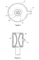
- the assembly 10 includes a housing 14, preferably translucent, of generally cylindrical form in this embodiment, which provides a chamber 16 therewithin.
- the shapes of the housing 14 and chamber 16 are not important although it is preferred that they are both generally round in axial cross-section.
- the housing 14 also includes a port 18 for the introduction of pressurization fluid into the chamber 16.
- the housing 14 is provided with circular holes 20, 22 at either end thereof, although again the shape of the holes is not critical. These holes 20, 22 allow for the passage of a catheter or other insert 24 therethrough, one being shown in dotted outline, and are of such a size that they are able to accommodate inserts 24 of the maximum size the sheath 12 can accept.
- a flexible valve element 26 is located within the chamber 16 and in this embodiment is supported by the housing 14 at each end thereof.
- the valve element 26 is cylindrical and stretched or pressurized to be of a waisted or hourglass shape.
- the valve element 26 seals the chamber 16 from the holes 20, 22, thereby providing a passage from one hole 20 to the other hole 22 which is completely sealed from any fluid in the chamber 16.
- valve element 26 is fixed to the inner surfaces of the housing 14 by any suitable means including gluing, heat sealing or by any mechanical fastening.
- valve element can be formed from one or more sheets of a thin compliant material, such as polyurethane, silicone, polychloroprene (Neoprene), styrene butadiene, styrene ethylene butadiene, latex, a rubber or rubberized material.
- a thin compliant material such as polyurethane, silicone, polychloroprene (Neoprene), styrene butadiene, styrene ethylene butadiene, latex, a rubber or rubberized material.
- the port 18 couples to a source 28 of pressurized fluid, which may include a syringe filled with a suitable fluid, a drop bag with fluid at a height giving a suitable pressure or a pump coupled to so as pump a suitable fluid from a supply. Described below are embodiments in which pressurization is effected by means of a coupling to a patient's blood back flow in the sheath in the vessel.
- the fluid may be water, saline solution, blood or any other suitable fluid including a gas or any safe air at a set pressure which gives a good compliance to selected sizes.
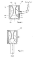
- Figure 3 shows in schematic form a cross-sectional view in side elevation of the valve assembly 10 of Figures 1 and 2 useful in understanding the operation of the valve element 26.
- this fluid applies a constricting force in all radial directions around the valve element 26 towards the axial centre of the device 10.
- This causes the valve element 26 to constrict, particularly at its centre or waist, which is furthest from the fixing points to the housing 14.
- This causes the valve element 26 to close around the passage 30 within the valve element 26 and between the two end holes 20, 22 in the housing 14.
- this force can cause sealing around big or small cylindrical elements or uneven shapes, or even complete closure of the passage 30 without any insert 24 being located therewithin. This is achieved by sufficient compression of the sides of the valve element 26 such that they eventually come into a central sealing configuration.
- the elasticity of the valve element 26 will enable it to close completely or almost completely, in dependence upon the pressure in the valve.
- valve 26 is located in the housing 14 substantially coaxially with the axis of the holes 20, 22 and is such as to close coaxially around the passage 30.
- an insert 24 within the valve assembly 10 such as an implant, a pusher or dilator or a guide wire, a diagnostic device, medical tools and the like.
- the valve element 26 seals against all such inserts, providing a reliable seal both when the insert is introduced as well as during its movement in the valve assembly 10.
- the seal provided by the pressurized fluid is a much more efficient seal than that provided by prior art systems, it is possible to provide a reliable seal without having to impart a large sealing force against the insert 24.
- the waist portion of the seal 26 will extend for a certain distance along an insert 24 placed in the valve which will be greater than the longitudinal sealing extent of a standard flat or pinched valve.
- the insert 24 can be fitted through and slid along the valve assembly 10 significantly more easily than with prior art devices.
- the clinician will pressurize the chamber 16 by application of the external pressure source (the syringe or pump, for example) via the port 18. This is preferably carried out before the delivery device is introduced into the patient.
- the external pressure source the syringe or pump, for example
- any fluid pressure from the patient's lumen in which the distal end of the deployment device is fed caused primarily from patient's blood pressure tending to open the valve element 26, will be countered by the closing pressure from the pressurized fluid within the chamber 16 as the area outside the valve is larger than that of its inner surface.
- the surgeon is provided with the ability to regulate pressure inside the chamber 16 and therefore the sealing pressure of the valve element 26.
- This can be achieved in its simplest form by tactile sensation on a syringe plunger.
- the system may be provided with a pressure meter, which could be provided within the assembly 10 but which in another embodiment is provided as a separate element coupled within the pressurized fluid supply path.
- the pressurization fluid is provided by the patient's own blood supply, this alternative does not require regulation because it could be considered to be effectively self-regulated by the blood pressure in the sheath.
- an open sheath without device held therein gives easy flow with high pressure and therefore provides a good sealing force. When a device is located in the sheath, the sheath could be described as almost filled, giving a lower sealing force but no need for a tight seal.
- the pressure of the fluid used to close the valve 26 can be varied as desired to take into account different insert sizes and to optimize the function and sealing characteristics of the valve assembly. This is a feature which is not possible with prior art devices.
- the valve element 26 will close when pressure is applied thereto, even when there is no insert 24, for the reason that the effective pressure applied to the external surfaces of the flexible valve element 26, even at its waisted portion, will be greater than that applied to the internal surface (that is surface facing the chamber 16 as opposed to the surface facing the internal passage), due to the greater surface area of the external surfaces of the valve relative to their opposing internal surfaces.
- the resultant pressure on the valve element 26 will be in a closing direction, as long as the absolute pressure within the chamber 16 is substantially not less than the absolute pressure within the housing 14 on the inside of the flexible valve member 26.
- the surgeon can carry out the other medical procedures without having to readjust the seal assembly 10, which provides an automatic and continuous seal.
- the surgeon may wish to reduce the pressure within the chamber 16 to facilitate further the insertion, or to raise the pressure on removal of insert 24, which could be done relatively easy by appropriate movement of the piston of a syringe providing pressurized fluid or by control of a pump where this is provided.
- a closure valve (not shown) is preferably placed between the syringe and the camber to maintain the desired pressure.
- the case 14 is of a substantially rigid construction, that is it is of a substantially fixed volume.
- the casing 14 could have some flexibility thereto to provide a varying volume.
- Figures 1 , 2 and 3 show a flexible valve element which extends continuously from one end of the casing 14 to the other, in effect completely sealing the chamber 16 from the passage between the holes 20, 22. It is not, however, essential to provide a complete seal between the chamber 16 and the passage 30.
- Figures 4 to 6 show alternative designs of flexible valve element 126 and 226 and means for pressurizing these into a sealing condition.
- valve element 126 extends to just beyond halfway in a longitudinal direction of the casing 114 and includes a narrow open end 128 and a larger upper end 130 which is fixed to the casing 114 and which surrounds the hole 120.
- Optional tethers 132, 134 tie the end 128 of the valve element 126 to the opposite end of the casing 114, adjacent the hole 122. These tethers assist in preventing eversion of the valve element 126 as a catheter, pusher or other insert 24 is passed through the valve assembly 100.
- valve element 126 since the surface area of the outside of the valve element 126 is greater than that of its inner surface, pressure applied within the chamber 116, from pressurized fluid 28 fed through the portal 18, will naturally cause valve element 126 to constrict at its open end 128 and therefore to provide a sealing action against a catheter, pusher or other insert 24.
- valve assembly 100 can be used also as a supply of fluid to the patient, such as saline solution, medicaments or any other fluid used during the medical treatment or diagnosis, as shown by the arrows in Figure 4 .
- fluid such as saline solution, medicaments or any other fluid used during the medical treatment or diagnosis.
- valve element 126 it can be advantageous to design valve element 126 such that its end 128 does not seal completely when there is no insert 124 within the valve assembly 100, in which case there is a passage of fluid through the port 18 and the end 128 into a patient's vessel or organ via the delivery device and in particular within the outer sheath 12 which in practice is coupled to the valve assembly 100.
- Figure 5 shows an example of arrangement in which the valve assembly 100 is coupled such that blood from the patient flows through the interstitial space between the sheath 12 and any insert 24 therein, around the openings or tethers 122, 134 and into the chamber so as to pressurize the valve 126 into a closed condition.
- the patient's blood pressure in the sheath which gives the pressure for operating the valve.
- this solution will not require any additional pressure regulation system as it can rely upon self-regulation from the patient's blood pressure. It is not, however, excluded that in some instances additional regulation, such as a syringe or pump, might be provided.
- valve element 226 which is of similar shape to the valve element of the embodiment of Figures 1 to 3 and which extends fully between holes or openings 220, 222 in the casing 210.
- the difference between the valve element 226 of this embodiment and the valve element 26 of the embodiment in Figures 1 to 3 is that the valve element 226 provided with at least one opening 228 therewithin, to provide a passage for fluid between the chamber 216 and the interior of the valve element 226.
- This has the same purpose as the design of valve element 126 shown in the embodiment of Figure 4 .
- Both embodiments of Figures 4 to 6 can be particularly advantageous when the patient's blood supply is used to provide the pressurized fluid into the chamber 116, 216.
- the patient's blood supply is used to provide the pressurized fluid into the chamber 116, 216.
- Figure 6 shows a fluid bag 230 for providing the source of pressurized fluid to operate the valve element 226.
- the fluid used will typically be a saline solution.
- the height of the bag 230 relative to the housing 210 which is preferably adjustable, will determine the pressure of the fluid in the housing 210 and therefore the closing pressure applied to the valve 226. Any leak in the valve will only leak out saline solution from the drop bag 230 into the sheath.
- the holes 228 in the valve 226 provide for passage of saline solution therethrough which thus to provide not only a source of pressurization fluid to close the valve 226 but also a source of saline solution to the patient.
- the number and size of the holes 228 in the valve 226 gives the maximum allowed flow of leaking fluid into the sheath.
- the drop bag 230 could be used with all of the embodiments of valve structure. Moreover, the valve 226 could be used in place of the valve 126 in the embodiments of Figures 4 and 5 .
- Figure 7 shows an arrangement which uses a patient's own blood pressure for pressurizing the valve 26.
- a coupling 250 to the patient's blood system via the sheath 12 passes to a chamber 252 which is divided in two by a flexible membrane 254, that is a into blood side 256 and a chamber side 258. Fluid is contained in sealed manner in the chamber side 308 and chamber 16.
- Blood pressure biases the membrane 204 towards the chamber side, thereby pressurizing the fluid in the chambers 258 and 16 to close the valve 26.
- valve element 26 there is no blood from the patient which is passed to the outside of the valve element 26, that is into the chamber 16.
- the patient's blood flow serves only to move the flexible membrane 254 so as to regulate pressure within the chamber 16.
- the outer surfaces of the valve element 26 have a greater surface area than its inner surfaces, there would be a greater force applied on the outside of the valve 26 by the patient's blood pressure, thereby causing the valve 26 to be biased closed.
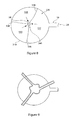
- Figure 8 shows in plan view an embodiment of valve structure useful for any of the valves shown in Figures 1 to 4 or any other valve configuration having the characteristics of the valves of those Figures.
- Figure 8 shows valve element 326 being formed of three leaflets 328, 330 and 332. These are in effect elongate sheets of valve material which are sealed to one another at longitudinal seals 334, 336 and 338, thereby to create a valve element 326 having the general hourglass shape shown in the preceding Figures. The three valve material sheets are sealed against the housing 18 to make a tight connection to the holes 20 and 22.
- this structure of valve element 326 provides a triangular passage 340 through the valve element 326 and thus through the valve assembly 310.
- valve element 386 may only have a tri-leaflet structure part way along its length, that is at its central portion.
- the three leaflets 328-332 would come in sealing contact with one another by folding over themselves and/or over one another, as can be seen in Figure 9 .
- this tri-leaflet valve element 326 could be pre-twisted, for example during manufacture, which can assist in its closure.
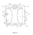
- the chamber 214 is formed of two parts 216, 218 which are able to nest one within the other in a fluid-tight manner. More particularly, the lower part 216, as viewed in Figure 10 , has a generally cylindrical casing 220 within which the valve element 26 is located as in the above-described embodiments.
- the cylindrical wall of the casing 220 is provided with first and second holes 222, 224.
- the part 216 is also provided with an outer cylindrical wall 226 co-axial with the casing 220 and sealed at one end by a lower annular wall between it and the casing 220.
- the other end of the wall 226 is open, providing an annular space 228 between it and the casing 220.
- the wall 226 is provided with one hole 230 which is aligned with the hole 222 in the inner casing 220, as can be seen in Figure 10 .
- the upper part 218 is provided with an annular depending cylindrical wall 238 which nests into the space 228, preferably in a substantially fluid tight manner by means of conventional sealing rings, and also has a hole 240 in its upper wall aligned with the holes 20, 22 in the casing 220 for the passage of a catheter therethrough.
- the hole 240 is preferably larger than the holes 20, 22.
- the upper part 218 is kept in an extended position, allowing direct passage through the holes 230 and 222 for sterilization moisture and gasses.
- the passage of gasses or fluids is depicted by the arrow 242 (at this time, the depending wall 238 is above the level of the holes 230, 222 as viewed in Figure 10 ).
- the upper part 218 is moved towards the lower part 220, such that the depending wall 238 nests and slides into the annular gap 228. In so doing, the depending wall passes between the holes 230, 222 in order to seal these from one another and the inside of the chamber 220 from the outside.
- valve 26 can perform its sealing function by a simple and effective manoeuvre by a surgeon or other clinician.
- the two parts 216 and 218 can be moved towards one another by pushing, by a screwing action (in which case they would be threadedly coupled to one another) or in any other way. It will be apparent that sufficient pressure for sealing could be achieved with very little movement of the parts 216 and 218 once the holes 230, 222 have been sealed closed.
- a friction fitting, adjustable ratchet or latching device, screw thread or any other device may be provided to keep the upper and lower parts in a sealing position relative to one another.
- valve element does not have to be formed of a compliant material as with existing haemostatic valves.
- the valve element could equally be formed of a relatively non-compliant material, such as a material commonly used for endovascular balloons, for example polyethylene terephathalate (PET), polyethylene, nylon, PVC, or any other known materials.
- PET polyethylene terephathalate
- An advantage of non-compliant materials of this type is that they can be very flexible and have lower coefficients of friction compared to compliant materials.
Landscapes
- Health & Medical Sciences (AREA)
- Heart & Thoracic Surgery (AREA)
- Pulmonology (AREA)
- Engineering & Computer Science (AREA)
- Anesthesiology (AREA)
- Biomedical Technology (AREA)
- Hematology (AREA)
- Life Sciences & Earth Sciences (AREA)
- Animal Behavior & Ethology (AREA)
- General Health & Medical Sciences (AREA)
- Public Health (AREA)
- Veterinary Medicine (AREA)
- Infusion, Injection, And Reservoir Apparatuses (AREA)
- Media Introduction/Drainage Providing Device (AREA)
- Endoscopes (AREA)
- Acyclic And Carbocyclic Compounds In Medicinal Compositions (AREA)
Claims (14)
- Hämostatische Ventilanordnung (220) mit einer Kammer (216), die unter Druck gesetzt werden kann, einem länglichen elastisch verformbaren Ventilelement (226), das in der Kammer (216) angeordnet ist, einem Durchgang, durch den ein längliches Element geführt werden kann, wobei das Ventilelement so angeordnet ist, dass es zumindest einen Teil des Durchgangs umhüllt, und Mitteln (230) zur Zufuhr von unter Druck stehender Flüssigkeit in die Kammer, worin die Druckbeaufschlagung der Kammer (216) dazu führt, dass das Ventilelement (226) zu einer geschlossenen Stellung hin vorgespannt wird; wobei die Anordnung eine Quelle von unter Druck stehender Flüssigkeit außerhalb der Kammer aufweist, worin die Quelle unter Druck stehender Flüssigkeit einen Tropfbeutel (230) aufweist.
- Hämostatische Ventilanordnung nach Anspruch 1, worin die Kammer (216) ein im Wesentlichen konstantes Volumen für die Druckbeaufschlagungsflüssigkeit bereitstellt.
- Hämostatische Ventilanordnung nach Anspruch 1, worin die Kammer (216) ein variables Volumenelement ist oder aufweist.
- Hämostatische Ventilanordnung (10) mit einer Kammer (16), die unter Druck gesetzt werden kann, einem länglichen elastisch verformbaren Ventilelement (26), das in der Kammer (16) angeordnet ist, einem Durchgang, durch den ein längliches Element geführt werden kann, wobei das Ventilelement (26) so angeordnet ist, dass es zumindest einen Teil des Durchgangs umhüllt, und Mitteln zur Zufuhr von unter Druck stehender Flüssigkeit in die Kammer, worin die Druckbeaufschlagung der Kammer dazu führt, dass das Ventilelement zu einer geschlossenen Stellung hin vorgespannt wird; wobei die Anordnung (10) eine Quelle von unter Druck stehender Flüssigkeit außerhalb der Kammer aufweist, worin die Quelle unter Druck stehender Flüssigkeit eine Kupplung (250-258) zur Ableitung von Druck aus dem Blutsystem eines Patienten aufweist.
- Hämostatische Ventilanordnung nach einem der vorhergehenden Ansprüche, worin das elastisch verformbare Ventil (26, 226) sanduhr- oder zylinderförmig ist.
- Hämostatische Ventilanordnung nach einem der vorhergehenden Ansprüche, worin das Ventilelement (26, 226) sich im Wesentlichen über den gesamten Durchgang bis zur Kammer erstreckt.
- Hämostatische Ventilanordnung nach Anspruch 6, worin das Ventilelement (26, 226) zur Kammer (16, 216) flüssigkeitsdicht ist.
- Hämostatische Ventilanordnung nach einem der Ansprüche 1 bis 5, worin das Ventil (226) sich nur über einen Teil des Durchgangs der Kammer erstreckt.
- Hämostatische Ventilanordnung nach Anspruch 8, die zumindest eine Fixierungsvorrichtung (172) zur Fixierung des freien Ventilendes aufweist.
- Hämostatische Ventilanordnung nach Anspruch 9, worin die oder jede Fixierungsvorrichtung einen Faden (132) aufweist.
- Hämostatische Ventilanordnung nach einem der vorhergehenden Ansprüche, worin das Ventilelement (26, 226) mit einem oder mehr Löchern (228) in den Durchgang in der Kammer versehen ist.
- Hämostatische Ventilanordnung nach einem der vorhergehenden Ansprüche, worin das Ventilelement (26, 226) eine Form mit mehreren Klappen aufweist.
- Einsatzvorrichtung mit einer hämostatischen Ventilanordnung (10) nach einem der vorhergehenden Ansprüche.
- Intravenöse Behandlungsanordnung mit einer hämostatischen Ventilanordnung (10) nach einem der vorhergehenden Ansprüche.
Applications Claiming Priority (2)
| Application Number | Priority Date | Filing Date | Title |
|---|---|---|---|
| US101807P | 2007-10-30 | 2007-10-30 | |
| PCT/US2008/012284 WO2009058308A1 (en) | 2007-10-30 | 2008-10-30 | Haemostatic valve |
Publications (2)
| Publication Number | Publication Date |
|---|---|
| EP2203211A1 EP2203211A1 (de) | 2010-07-07 |
| EP2203211B1 true EP2203211B1 (de) | 2011-04-13 |
Family
ID=40291310
Family Applications (1)
| Application Number | Title | Priority Date | Filing Date |
|---|---|---|---|
| EP08845537A Not-in-force EP2203211B1 (de) | 2007-10-30 | 2008-10-30 | Hämostatisches ventil |
Country Status (6)
| Country | Link |
|---|---|
| US (1) | US8118784B2 (de) |
| EP (1) | EP2203211B1 (de) |
| JP (1) | JP5332048B2 (de) |
| AT (1) | ATE505227T1 (de) |
| DE (1) | DE602008006238D1 (de) |
| WO (1) | WO2009058308A1 (de) |
Families Citing this family (15)
| Publication number | Priority date | Publication date | Assignee | Title |
|---|---|---|---|---|
| US8025640B2 (en) * | 2008-06-27 | 2011-09-27 | Tyco Healthcare Group Lp | Pressurized surgical valve |
| US8403822B2 (en) * | 2009-02-20 | 2013-03-26 | Cytyc Corporation | Passive vent for brachytherapy balloon catheters |
| US8366667B2 (en) * | 2010-02-11 | 2013-02-05 | Baxter International Inc. | Flow pulsatility dampening devices |
| GB2480272B (en) * | 2010-05-11 | 2012-10-10 | Cook Medical Technologies Llc | Haemostatic valve assembly |
| CA2802883A1 (en) * | 2010-06-14 | 2011-12-22 | University Of Manitoba | Method and apparatus for retroperfusion |
| US9440059B2 (en) * | 2011-03-18 | 2016-09-13 | Cook Medical Technologies Llc | Adjustable diameter hemostatic valve |
| EP2540338B1 (de) * | 2011-06-03 | 2015-09-16 | Cook Medical Technologies LLC | Hämostatisches Ventil mit mehrschichtiger Ventilstruktur |
| US9707076B2 (en) * | 2012-08-23 | 2017-07-18 | Minimally Invasive Surgical Access Limited | Direct aortic access system for transcatheter aortic valve procedures |
| CA2996690A1 (en) * | 2015-08-27 | 2017-03-02 | Avent, Inc. | Variable flow rate control device |
| US10625058B2 (en) * | 2016-03-04 | 2020-04-21 | C.R. Bard, Inc. | Perfusion balloon with external valve |
| US11565090B2 (en) * | 2016-03-04 | 2023-01-31 | C.R. Bard, Inc. | Perfusion balloon with internal valve |
| CN113117226B (zh) * | 2019-12-31 | 2025-07-01 | 杭州启明医疗器械股份有限公司 | 反馈调节式止血阀、导管鞘以及介入器械的密封方法 |
| US11752317B2 (en) | 2020-02-04 | 2023-09-12 | Medtronic, Inc. | Hemostasis valve orientation relative to the fluid space in a introducer sheath |
| WO2024226595A1 (en) | 2023-04-27 | 2024-10-31 | Cultiv8 1, LLC | Introducer sheath systems and methods |
| CN117100196B (zh) * | 2023-10-25 | 2024-02-06 | 杭州好克光电仪器有限公司 | 一种内窥镜的隔离阀组件 |
Family Cites Families (26)
| Publication number | Priority date | Publication date | Assignee | Title |
|---|---|---|---|---|
| US2590215A (en) * | 1947-02-21 | 1952-03-25 | Frank C Sausa | Variable throat restricter valve |
| JPS61154679A (ja) * | 1984-12-28 | 1986-07-14 | テルモ株式会社 | 体内導入套管 |
| US4642833A (en) * | 1985-03-14 | 1987-02-17 | Coxwold (Proprietary) Limited | Valve assembly |
| US4946133A (en) * | 1988-11-21 | 1990-08-07 | Schneider (U.S.A.) Inc., A Pfizer Co. | Hemostasis valve |
| US4932959A (en) * | 1988-12-01 | 1990-06-12 | Advanced Cardiovascular Systems, Inc. | Vascular catheter with releasably secured guidewire |
| US5176652A (en) * | 1989-12-22 | 1993-01-05 | Cordis Corporation | Hemostasis valve |
| US5071411A (en) * | 1990-03-26 | 1991-12-10 | Cordis Corporation | Pressure-actuated valve for sealing flow conduit |
| US5161773A (en) * | 1990-08-01 | 1992-11-10 | Numed, Inc. | Method and apparatus for controlling fluid flow |
| US5395349A (en) * | 1991-12-13 | 1995-03-07 | Endovascular Technologies, Inc. | Dual valve reinforced sheath and method |
| CA2093748C (en) | 1992-04-24 | 1996-11-12 | Roy D. Gravener | Valve assembly for introducing instruments into body cavities |
| US5338313A (en) * | 1992-12-17 | 1994-08-16 | Thomas J. Fogarty, M.D. | Adjustable valve having a radially compressible sealing body |
| US5391154A (en) * | 1993-08-30 | 1995-02-21 | United States Surgical Corporation | Trocar seal system |
| US5634937A (en) * | 1995-05-19 | 1997-06-03 | General Surgical Innovations, Inc. | Skin seal with inflatable membrane |
| EP0780580B1 (de) * | 1995-12-22 | 2003-02-12 | FESTO AG & Co | Vorrichtung zur Erzeugung von periodischen Impulsänderungen in einer Fluid-Strömung, Verfahren zum Betrieb der Vorrichtung und deren Verwendung |
| US5814026A (en) * | 1996-03-19 | 1998-09-29 | Yoon; Inbae | Endoscopic portal having a universal seal and methods for introducing instruments therethrough |
| US5797879A (en) * | 1996-08-26 | 1998-08-25 | Decampli; William M. | Apparatus and methods for providing selectively adjustable blood flow through a vascular graft |
| US5895376A (en) * | 1996-10-23 | 1999-04-20 | Mayo Foundation For Medical Education And Research | Hemostasis valve, system and assembly |
| US5807312A (en) * | 1997-05-23 | 1998-09-15 | Dzwonkiewicz; Mark R. | Bolus pump apparatus |
| WO1999024097A1 (en) * | 1997-11-12 | 1999-05-20 | Stereotaxis, Inc. | Intracranial bolt and method of placing and using an intracranial bolt to position a medical device |
| EP1280579B1 (de) * | 2000-04-28 | 2013-06-19 | Cirque Medical Incorporated | Multiluminales intravenöses verländerungsstück |
| EP1558154B1 (de) * | 2002-11-08 | 2009-01-14 | Tyco Healthcare Group Lp | Selbstverschliessende kanüle |
| EP1622657B1 (de) * | 2003-04-23 | 2011-06-08 | Interrad Medical, Inc. | Dialyseventil |
| EP1691884B1 (de) * | 2003-12-11 | 2011-03-23 | Cook Incorporated | Hämostaseventilanordnung |
| FR2872696B1 (fr) * | 2004-07-07 | 2007-09-28 | Perouse Soc Par Actions Simpli | Introducteur pour intervention endoluminale |
| US7118086B1 (en) * | 2005-03-04 | 2006-10-10 | Richway Industries Ltd. | Pinch valve with inlet and outlet ports |
| EP1883239A1 (de) | 2006-07-24 | 2008-01-30 | Nagravision S.A. | Verfahren zum Speichern und zum Betrieb von Rundsendeereignisdaten |
-
2008
- 2008-10-22 US US12/288,705 patent/US8118784B2/en active Active
- 2008-10-30 DE DE602008006238T patent/DE602008006238D1/de active Active
- 2008-10-30 EP EP08845537A patent/EP2203211B1/de not_active Not-in-force
- 2008-10-30 AT AT08845537T patent/ATE505227T1/de not_active IP Right Cessation
- 2008-10-30 WO PCT/US2008/012284 patent/WO2009058308A1/en not_active Ceased
- 2008-10-30 JP JP2010531071A patent/JP5332048B2/ja not_active Expired - Fee Related
Also Published As
| Publication number | Publication date |
|---|---|
| US20090118681A1 (en) | 2009-05-07 |
| JP5332048B2 (ja) | 2013-11-06 |
| EP2203211A1 (de) | 2010-07-07 |
| WO2009058308A1 (en) | 2009-05-07 |
| DE602008006238D1 (de) | 2011-05-26 |
| US8118784B2 (en) | 2012-02-21 |
| JP2011502001A (ja) | 2011-01-20 |
| ATE505227T1 (de) | 2011-04-15 |
Similar Documents
| Publication | Publication Date | Title |
|---|---|---|
| US8118784B2 (en) | Haemostatic valve | |
| US11648357B2 (en) | Methods, systems, and devices for sealing and flusing a delivery system | |
| EP2427244B1 (de) | Hämostatische ventilanordnung | |
| US6602240B2 (en) | Method and device for maintaining a seal | |
| US10201421B2 (en) | Tip for medical implant delivery system | |
| EP2500058B1 (de) | Blutstillendes Ventil mit einstellbarem Durchmesser | |
| AU2008319319B2 (en) | Haemostatic valve | |
| JP2009261963A (ja) | 止血安全弁を備えた血管アクセス装置 | |
| JP2009187536A (ja) | 制限装置を調節するための定力機構 | |
| US20210260355A1 (en) | Valved introducer sheath | |
| US20240016604A1 (en) | Catheter systems with hydraulic shock arrestor | |
| EP2635342B1 (de) | Hämostatische ventilanordnung | |
| EP4444401A2 (de) | Vorrichtung und verfahren zur befestigung einer medizinischen vorrichtung an einem patienten | |
| WO2010028021A1 (en) | Valve assembly and introducer | |
| US12582409B2 (en) | Devices and methods for blood flow regulation | |
| EP4442308A1 (de) | Zugangsvorrichtung zum einbringen von länglichen geräten in den körper eines lebewesens |
Legal Events
| Date | Code | Title | Description |
|---|---|---|---|
| PUAI | Public reference made under article 153(3) epc to a published international application that has entered the european phase |
Free format text: ORIGINAL CODE: 0009012 |
|
| 17P | Request for examination filed |
Effective date: 20100219 |
|
| AK | Designated contracting states |
Kind code of ref document: A1 Designated state(s): AT BE BG CH CY CZ DE DK EE ES FI FR GB GR HR HU IE IS IT LI LT LU LV MC MT NL NO PL PT RO SE SI SK TR |
|
| AX | Request for extension of the european patent |
Extension state: AL BA MK RS |
|
| GRAP | Despatch of communication of intention to grant a patent |
Free format text: ORIGINAL CODE: EPIDOSNIGR1 |
|
| DAX | Request for extension of the european patent (deleted) | ||
| GRAS | Grant fee paid |
Free format text: ORIGINAL CODE: EPIDOSNIGR3 |
|
| GRAA | (expected) grant |
Free format text: ORIGINAL CODE: 0009210 |
|
| AK | Designated contracting states |
Kind code of ref document: B1 Designated state(s): AT BE BG CH CY CZ DE DK EE ES FI FR GB GR HR HU IE IS IT LI LT LU LV MC MT NL NO PL PT RO SE SI SK TR |
|
| REG | Reference to a national code |
Ref country code: GB Ref legal event code: FG4D |
|
| REG | Reference to a national code |
Ref country code: CH Ref legal event code: EP |
|
| REG | Reference to a national code |
Ref country code: IE Ref legal event code: FG4D |
|
| REF | Corresponds to: |
Ref document number: 602008006238 Country of ref document: DE Date of ref document: 20110526 Kind code of ref document: P |
|
| REG | Reference to a national code |
Ref country code: DE Ref legal event code: R096 Ref document number: 602008006238 Country of ref document: DE Effective date: 20110526 |
|
| REG | Reference to a national code |
Ref country code: NL Ref legal event code: VDEP Effective date: 20110413 |
|
| LTIE | Lt: invalidation of european patent or patent extension |
Effective date: 20110413 |
|
| RAP2 | Party data changed (patent owner data changed or rights of a patent transferred) |
Owner name: COOK MEDICAL TECHNOLOGIES LLC |
|
| PG25 | Lapsed in a contracting state [announced via postgrant information from national office to epo] |
Ref country code: NO Free format text: LAPSE BECAUSE OF FAILURE TO SUBMIT A TRANSLATION OF THE DESCRIPTION OR TO PAY THE FEE WITHIN THE PRESCRIBED TIME-LIMIT Effective date: 20110713 Ref country code: LT Free format text: LAPSE BECAUSE OF FAILURE TO SUBMIT A TRANSLATION OF THE DESCRIPTION OR TO PAY THE FEE WITHIN THE PRESCRIBED TIME-LIMIT Effective date: 20110413 Ref country code: PT Free format text: LAPSE BECAUSE OF FAILURE TO SUBMIT A TRANSLATION OF THE DESCRIPTION OR TO PAY THE FEE WITHIN THE PRESCRIBED TIME-LIMIT Effective date: 20110816 Ref country code: HR Free format text: LAPSE BECAUSE OF FAILURE TO SUBMIT A TRANSLATION OF THE DESCRIPTION OR TO PAY THE FEE WITHIN THE PRESCRIBED TIME-LIMIT Effective date: 20110413 Ref country code: SE Free format text: LAPSE BECAUSE OF FAILURE TO SUBMIT A TRANSLATION OF THE DESCRIPTION OR TO PAY THE FEE WITHIN THE PRESCRIBED TIME-LIMIT Effective date: 20110413 |
|
| PG25 | Lapsed in a contracting state [announced via postgrant information from national office to epo] |
Ref country code: LV Free format text: LAPSE BECAUSE OF FAILURE TO SUBMIT A TRANSLATION OF THE DESCRIPTION OR TO PAY THE FEE WITHIN THE PRESCRIBED TIME-LIMIT Effective date: 20110413 Ref country code: ES Free format text: LAPSE BECAUSE OF FAILURE TO SUBMIT A TRANSLATION OF THE DESCRIPTION OR TO PAY THE FEE WITHIN THE PRESCRIBED TIME-LIMIT Effective date: 20110724 Ref country code: FI Free format text: LAPSE BECAUSE OF FAILURE TO SUBMIT A TRANSLATION OF THE DESCRIPTION OR TO PAY THE FEE WITHIN THE PRESCRIBED TIME-LIMIT Effective date: 20110413 Ref country code: GR Free format text: LAPSE BECAUSE OF FAILURE TO SUBMIT A TRANSLATION OF THE DESCRIPTION OR TO PAY THE FEE WITHIN THE PRESCRIBED TIME-LIMIT Effective date: 20110714 Ref country code: SI Free format text: LAPSE BECAUSE OF FAILURE TO SUBMIT A TRANSLATION OF THE DESCRIPTION OR TO PAY THE FEE WITHIN THE PRESCRIBED TIME-LIMIT Effective date: 20110413 Ref country code: CY Free format text: LAPSE BECAUSE OF FAILURE TO SUBMIT A TRANSLATION OF THE DESCRIPTION OR TO PAY THE FEE WITHIN THE PRESCRIBED TIME-LIMIT Effective date: 20110413 Ref country code: IS Free format text: LAPSE BECAUSE OF FAILURE TO SUBMIT A TRANSLATION OF THE DESCRIPTION OR TO PAY THE FEE WITHIN THE PRESCRIBED TIME-LIMIT Effective date: 20110813 Ref country code: BE Free format text: LAPSE BECAUSE OF FAILURE TO SUBMIT A TRANSLATION OF THE DESCRIPTION OR TO PAY THE FEE WITHIN THE PRESCRIBED TIME-LIMIT Effective date: 20110413 Ref country code: AT Free format text: LAPSE BECAUSE OF FAILURE TO SUBMIT A TRANSLATION OF THE DESCRIPTION OR TO PAY THE FEE WITHIN THE PRESCRIBED TIME-LIMIT Effective date: 20110413 |
|
| PG25 | Lapsed in a contracting state [announced via postgrant information from national office to epo] |
Ref country code: NL Free format text: LAPSE BECAUSE OF FAILURE TO SUBMIT A TRANSLATION OF THE DESCRIPTION OR TO PAY THE FEE WITHIN THE PRESCRIBED TIME-LIMIT Effective date: 20110413 |
|
| RAP2 | Party data changed (patent owner data changed or rights of a patent transferred) |
Owner name: COOK MEDICAL TECHNOLOGIES LLC |
|
| PG25 | Lapsed in a contracting state [announced via postgrant information from national office to epo] |
Ref country code: EE Free format text: LAPSE BECAUSE OF FAILURE TO SUBMIT A TRANSLATION OF THE DESCRIPTION OR TO PAY THE FEE WITHIN THE PRESCRIBED TIME-LIMIT Effective date: 20110413 Ref country code: CZ Free format text: LAPSE BECAUSE OF FAILURE TO SUBMIT A TRANSLATION OF THE DESCRIPTION OR TO PAY THE FEE WITHIN THE PRESCRIBED TIME-LIMIT Effective date: 20110413 |
|
| PLBE | No opposition filed within time limit |
Free format text: ORIGINAL CODE: 0009261 |
|
| STAA | Information on the status of an ep patent application or granted ep patent |
Free format text: STATUS: NO OPPOSITION FILED WITHIN TIME LIMIT |
|
| PG25 | Lapsed in a contracting state [announced via postgrant information from national office to epo] |
Ref country code: SK Free format text: LAPSE BECAUSE OF FAILURE TO SUBMIT A TRANSLATION OF THE DESCRIPTION OR TO PAY THE FEE WITHIN THE PRESCRIBED TIME-LIMIT Effective date: 20110413 Ref country code: PL Free format text: LAPSE BECAUSE OF FAILURE TO SUBMIT A TRANSLATION OF THE DESCRIPTION OR TO PAY THE FEE WITHIN THE PRESCRIBED TIME-LIMIT Effective date: 20110413 Ref country code: DK Free format text: LAPSE BECAUSE OF FAILURE TO SUBMIT A TRANSLATION OF THE DESCRIPTION OR TO PAY THE FEE WITHIN THE PRESCRIBED TIME-LIMIT Effective date: 20110413 Ref country code: RO Free format text: LAPSE BECAUSE OF FAILURE TO SUBMIT A TRANSLATION OF THE DESCRIPTION OR TO PAY THE FEE WITHIN THE PRESCRIBED TIME-LIMIT Effective date: 20110413 |
|
| 26N | No opposition filed |
Effective date: 20120116 |
|
| REG | Reference to a national code |
Ref country code: DE Ref legal event code: R097 Ref document number: 602008006238 Country of ref document: DE Effective date: 20120116 |
|
| PG25 | Lapsed in a contracting state [announced via postgrant information from national office to epo] |
Ref country code: MC Free format text: LAPSE BECAUSE OF NON-PAYMENT OF DUE FEES Effective date: 20111031 Ref country code: IT Free format text: LAPSE BECAUSE OF FAILURE TO SUBMIT A TRANSLATION OF THE DESCRIPTION OR TO PAY THE FEE WITHIN THE PRESCRIBED TIME-LIMIT Effective date: 20110413 |
|
| REG | Reference to a national code |
Ref country code: FR Ref legal event code: ST Effective date: 20120629 |
|
| PG25 | Lapsed in a contracting state [announced via postgrant information from national office to epo] |
Ref country code: FR Free format text: LAPSE BECAUSE OF NON-PAYMENT OF DUE FEES Effective date: 20111102 |
|
| PG25 | Lapsed in a contracting state [announced via postgrant information from national office to epo] |
Ref country code: MT Free format text: LAPSE BECAUSE OF FAILURE TO SUBMIT A TRANSLATION OF THE DESCRIPTION OR TO PAY THE FEE WITHIN THE PRESCRIBED TIME-LIMIT Effective date: 20110413 |
|
| PG25 | Lapsed in a contracting state [announced via postgrant information from national office to epo] |
Ref country code: LU Free format text: LAPSE BECAUSE OF NON-PAYMENT OF DUE FEES Effective date: 20111030 |
|
| REG | Reference to a national code |
Ref country code: CH Ref legal event code: PL |
|
| PG25 | Lapsed in a contracting state [announced via postgrant information from national office to epo] |
Ref country code: BG Free format text: LAPSE BECAUSE OF FAILURE TO SUBMIT A TRANSLATION OF THE DESCRIPTION OR TO PAY THE FEE WITHIN THE PRESCRIBED TIME-LIMIT Effective date: 20110713 |
|
| PG25 | Lapsed in a contracting state [announced via postgrant information from national office to epo] |
Ref country code: LI Free format text: LAPSE BECAUSE OF NON-PAYMENT OF DUE FEES Effective date: 20121031 Ref country code: CH Free format text: LAPSE BECAUSE OF NON-PAYMENT OF DUE FEES Effective date: 20121031 |
|
| PG25 | Lapsed in a contracting state [announced via postgrant information from national office to epo] |
Ref country code: TR Free format text: LAPSE BECAUSE OF FAILURE TO SUBMIT A TRANSLATION OF THE DESCRIPTION OR TO PAY THE FEE WITHIN THE PRESCRIBED TIME-LIMIT Effective date: 20110413 |
|
| PG25 | Lapsed in a contracting state [announced via postgrant information from national office to epo] |
Ref country code: HU Free format text: LAPSE BECAUSE OF FAILURE TO SUBMIT A TRANSLATION OF THE DESCRIPTION OR TO PAY THE FEE WITHIN THE PRESCRIBED TIME-LIMIT Effective date: 20110413 |
|
| PGFP | Annual fee paid to national office [announced via postgrant information from national office to epo] |
Ref country code: IE Payment date: 20220926 Year of fee payment: 15 Ref country code: GB Payment date: 20220914 Year of fee payment: 15 |
|
| PGFP | Annual fee paid to national office [announced via postgrant information from national office to epo] |
Ref country code: DE Payment date: 20220914 Year of fee payment: 15 |
|
| REG | Reference to a national code |
Ref country code: DE Ref legal event code: R119 Ref document number: 602008006238 Country of ref document: DE |
|
| GBPC | Gb: european patent ceased through non-payment of renewal fee |
Effective date: 20231030 |
|
| PG25 | Lapsed in a contracting state [announced via postgrant information from national office to epo] |
Ref country code: GB Free format text: LAPSE BECAUSE OF NON-PAYMENT OF DUE FEES Effective date: 20231030 |
|
| PG25 | Lapsed in a contracting state [announced via postgrant information from national office to epo] |
Ref country code: GB Free format text: LAPSE BECAUSE OF NON-PAYMENT OF DUE FEES Effective date: 20231030 Ref country code: DE Free format text: LAPSE BECAUSE OF NON-PAYMENT OF DUE FEES Effective date: 20240501 |
|
| PG25 | Lapsed in a contracting state [announced via postgrant information from national office to epo] |
Ref country code: IE Free format text: LAPSE BECAUSE OF NON-PAYMENT OF DUE FEES Effective date: 20231030 |
|
| PG25 | Lapsed in a contracting state [announced via postgrant information from national office to epo] |
Ref country code: IE Free format text: LAPSE BECAUSE OF NON-PAYMENT OF DUE FEES Effective date: 20231030 |