EP2203328B1 - Fahrzeugsitz mit einer für den benutzungsfall aufbaubaren tischstruktur - Google Patents
Fahrzeugsitz mit einer für den benutzungsfall aufbaubaren tischstruktur Download PDFInfo
- Publication number
- EP2203328B1 EP2203328B1 EP08803920.1A EP08803920A EP2203328B1 EP 2203328 B1 EP2203328 B1 EP 2203328B1 EP 08803920 A EP08803920 A EP 08803920A EP 2203328 B1 EP2203328 B1 EP 2203328B1
- Authority
- EP
- European Patent Office
- Prior art keywords
- support
- vehicle seat
- table support
- table top
- carrier
- Prior art date
- Legal status (The legal status is an assumption and is not a legal conclusion. Google has not performed a legal analysis and makes no representation as to the accuracy of the status listed.)
- Not-in-force
Links
- 238000010276 construction Methods 0.000 description 5
- 230000037237 body shape Effects 0.000 description 1
- 238000003780 insertion Methods 0.000 description 1
- 230000037431 insertion Effects 0.000 description 1
- 238000009434 installation Methods 0.000 description 1
- 239000007787 solid Substances 0.000 description 1
Images



Classifications
-
- B—PERFORMING OPERATIONS; TRANSPORTING
- B60—VEHICLES IN GENERAL
- B60N—SEATS SPECIALLY ADAPTED FOR VEHICLES; VEHICLE PASSENGER ACCOMMODATION NOT OTHERWISE PROVIDED FOR
- B60N3/00—Arrangements or adaptations of other passenger fittings, not otherwise provided for
- B60N3/001—Arrangements or adaptations of other passenger fittings, not otherwise provided for of tables or trays
-
- B—PERFORMING OPERATIONS; TRANSPORTING
- B60—VEHICLES IN GENERAL
- B60N—SEATS SPECIALLY ADAPTED FOR VEHICLES; VEHICLE PASSENGER ACCOMMODATION NOT OTHERWISE PROVIDED FOR
- B60N2/00—Seats specially adapted for vehicles; Arrangement or mounting of seats in vehicles
- B60N2/75—Arm-rests
- B60N2/79—Adaptations for additional use of the arm-rests
Definitions
- the invention relates to a vehicle seat with a buildable for the case of use table structure, wherein it has at least one extendable table support and the table structure is provided with a table top having at least on one side a pivotally mounted table support, wherein the at least one table support on the table top is mounted so pivotally that the table top is held in a horizontal position in the assembled state of the table structure.
- Such a vehicle seat is for example from the EP-A-1160125 or even the DE-A-10044414 known.
- the table structures are integrally connected to the associated vehicle seat.
- a folding table in a backrest of a front seat is available, which can be used individually or for catering services in the square and thus represents a comfort.
- vehicle seats can be provided in a pure row seating for the passengers of the front row of seats in a functionality and comfort comparable service table, mostly due to the seat construction and lack of possible arrangements in the area. Even if the appropriate installation space would be available in individual cases, extensive and costly structural measures would be required, of which the entire seat construction and possibly adjacent components such as the rail vehicle, for example, the Wagenkastenrohbau and a side wall paneling would be affected.
- a known solution is to provide a Vis-a-vis seating with a table installed between a first and a second row of seats. This requires a greater construction effort and has the disadvantage that it must be dispensed with a rotation of the seats, if for each seat a table space should be available.
- a combined pivoting folding table is attached laterally to the seat.
- this table When not in use, this table is in one Stowed shaft, the top of which is done by the armrest pad.
- This shaft is a solid side wall of the seat, which can not be performed by their manner of construction non-movable. Such a construction is also precluded when a hinged armrest is required, which, when placed in a vertical position, allows a more comfortable exit from the seat.
- the invention has the object, a vehicle seat of the type mentioned further such that independent of a respective vehicle seat environment, a service table can be provided.
- the table structure forms a separable unit with the vehicle seat, in which the table support for supporting the table top is inserted into the table support and a free end of the table support is designed for positive support in an associated receptacle of the table support.
- the table structure can be essentially independent of an arrangement of the vehicle seat to build within a vehicle.
- the solution includes that the table structure forms a separable unit with the vehicle seat, because the proposed table support is inserted to support the table top in the table support, in particular in an extendable support arm, for example from above.
- the at least one table support has at its free end a bearing journal, which engages in the assembled state of the table structure in a bearing slot of a table support arm of the table support. This causes a secure support of the table support on the table support.
- the bearing journal may each have a shoulder at its front and its rear end, which engages in a correspondingly offset recess in the carrier arm. In this way it is ensured that a relative movement of the table support in the longitudinal direction of the table support is effectively prevented. Relative movements between the table support and table support in the transverse direction can be avoided by suitable arrangement of boundary walls of the support arm in the region of the bearing slot.
- the support arm For easy handling of the support arm it can be provided with an end-side handle and stored in a guide.
- the at least one table support is pivotally mounted on the table top, that a maximum angle for the pivotal movement between the table top and the table support is limited to an angle of 90 °.
- a maximum angle for the pivotal movement between the table top and the table support is limited to an angle of 90 °.
- only one side of the table top can be used as a usable area.
- the at least one table support can be mounted on the table top such that a maximum angle for the pivoting movement between the Table support and the table top is limited to +/- 90 °.
- both sides of the table top can be provided with symmetrical design as effective area.
- a further table support is provided on the side opposite the at least one table support side of the table top, which is formed for support with its free end on an associated second table support.
- This second table support is preferably also extendable. In this way, the table top is supported on both sides.
- the other table support can be pivotally mounted on the table top.
- the further table support has a downwardly open tab which is provided for gripping around the further support arm.
- the other table support can be releasably attached to the associated table support.
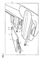
- FIG. 1 shows a vehicle seat 1, which is equipped in the usual way with two armrests 2. On an underside of each armrest 2 extendable table support 3 are provided, each having support arms 5 which are extendable by actuation of an end-side handle 4 from a guide.
- FIG. 1 In the exploded view of FIG. 1 is above the support arms 5, a table structure 6 is shown, which has a table top 7 and on both sides of the table top 7 pivotally hinged table supports 8, 9.
- Joints 10 for the storage of the table supports 8, 9 on the table top 7 allow relative angular positions of the table supports 8, 9 to the table top 7 within maximum angles of +/- 90 °, so that the table structure 6 basically as in FIG. 1 represented as mirror-inverted on the support arms 5 can be supported.
- the two table supports 8, 9 are substantially identical, but the table support 8 has a bearing pin 11 which is not present in the table support 9. With vertical alignment of the table supports 8, 9, the table support 8 extends according to the length of the bearing pin 11 further down than the table support. 9
- FIG. 2 It also shows an engagement of the bearing pin 11 in an associated slot-shaped recess 12 of the support arm fifth illustrated.
- a longitudinal extent of the slot-shaped recess 12 corresponds to the top of the support arm 5 of those of the table support 8 above the journal 11.
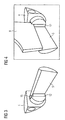
- the journal 11 connects to the rest of the table support 8 via paragraphs 13, 14 at. Accordingly, compare FIG. 3 for the front shoulder 13, also the longitudinal extent of the slot-shaped recess 12 has a shoulder 15 which cooperates with the shoulder 13 of the table support 8.
- the bearing pin 11 engages positively in the slot-shaped recess 12, also with respect to a relative transverse movement, so that all possible relative movements of the table support 8 are effectively avoided to the support arm 5.
- FIG. 5 shows the fully assembled table structure 6, in which the rear table support shown in the figure 8 is provided with the bearing pin 11, the lower end of which projects slightly from the associated support arm 5 from.
- the passenger facing a table edge of the table top 7 is adapted by a slight rounding of a body shape.
- the tabletop 6 remains through the hinge 10 on the positive storage of the journal 11 rotatable so that the vehicle seat 1 can be left unhindered, for example, in a panic situation.
Landscapes
- Engineering & Computer Science (AREA)
- Transportation (AREA)
- Mechanical Engineering (AREA)
- Aviation & Aerospace Engineering (AREA)
- Passenger Equipment (AREA)
- Vehicle Step Arrangements And Article Storage (AREA)
Description
- Die Erfindung bezieht sich auf einen Fahrzeugsitz mit einer für den Benutzungsfall aufbaubaren Tischstruktur, wobei er wenigstens einen ausziehbaren Tischträger aufweist und die Tischstruktur mit einer Tischplatte vorgesehen ist, die wenigstens an einer Seite eine schwenkbar gelagerte Tischstütze aufweist, wobei die wenigstens eine Tischstütze an der Tischplatte derart schwenkbar gelagert ist, dass im aufgebauten Zustand der Tischstruktur die Tischplatte in einer horizontalen Lage gehalten ist.
- Ein solcher Fahrzeugsitz ist beispielsweise aus der
EP-A-1160125 oder auch derDE-A-10044414 bekannt. Dabei sind jeweils die Tischstrukturen mit dem zugehörigen Fahrzeugsitz integral verbunden. - Üblicherweise steht Fahrgästen zumindest in einer gehobenen Fahrzeugklasse ein Klapptisch in einer Rückenlehne eines Vordersitzes zur Verfügung, der individuell bzw. für Catering-Dienste am Platz genutzt werden kann und somit eine Komfortsteigerung darstellt. Bei den meisten bekannten Fahrzeugsitzen kann bei einer reinen Reihenbestuhlung für die Fahrgäste der vordersten Sitzreihe ein in Funktionalität und Komfort vergleichbarer Servicetisch nicht vorgesehen werden, zumeist bedingt durch die Sitzkonstruktion und fehlende Anordnungsmöglichkeiten in der Umgebung. Selbst wenn der entsprechende Bauraum im Einzelfall zur Verfügung stehen würde, wären umfangreiche und kostenintensive bauliche Maßnahmen erforderlich, von denen die gesamte Sitzkonstruktion und ggf. angrenzende Komponenten wie beim Schienenfahrzeug zum Beispiel der Wagenkastenrohbau und eine Seitenwandverkleidung, betroffen wären.
- Eine bekannte Lösung besteht darin, eine Vis-a-vis-Bestuhlung mit einem ortsfest zwischen einer ersten und einer zweiten Sitzreihe installierten Tisch vorzusehen. Dies bedingt einen größeren baulichen Aufwand und birgt den Nachteil in sich, dass auf eine Drehbarkeit der Sitze verzichtet werden muss, wenn für jeden Sitz ein Tischplatz zur Verfügung stehen soll.
- Bekannt sind außerdem Ausführungsformen von Fahrzeugsitzen, bei denen ein kombinierter Schwenkklapptisch seitlich am Sitz befestigt ist. Bei Nichtgebrauch wird dieser Tisch in einem Schacht verstaut, dessen oberer Abschluss durch die Armlehnenauflage erfolgt. Dieser Schacht stellt eine feste Seitenwange des Sitzes dar, die durch ihre Art und Weise der Konstruktion nicht beweglich ausgeführt werden kann. Eine solche Konstruktion ist zudem ausgeschlossen, wenn eine drehbare Armlehne gefordert ist, die, in eine senkrechte Position gebracht, ein bequemeres Verlassen des Sitzes ermöglicht.
- Ausgehend hiervon liegt der Erfindung die Aufgabe zugrunde, einen Fahrzeugsitz der eingangs genannten Art derart weiterzuentwickeln, dass unabhängiger von einer jeweiligen Fahrzeugsitzumgebung ein Servicetisch bereitgestellt werden kann.
- Diese Aufgabe wird dadurch gelöst, dass die Tischstruktur eine trennbare Einheit mit dem Fahrzeugsitz bildet, in dem die Tischstütze zur Abstützung der Tischplatte in den Tischträger eingesteckt wird und ein freies Ende der Tischstütze zur formschlüssigen Abstützung in einer zugeordneten Aufnahme des Tischträgers ausgebildet ist.
- Da ein solcher Tischträger, der ausziehbar ist, an jeder Art von Fahrzeugsitzen vorgesehen werden kann, beispielsweise unterhalb einer jeweiligen Armlehne, lässt sich die Tischstruktur im Wesentlichen unabhängig von einer Anordnung des Fahrzeugsitzes innerhalb eines Fahrzeuges aufbauen. Die Lösung beinhaltet, dass die Tischstruktur eine trennbare Einheit mit dem Fahrzeugsitz bildet, denn die vorgesehene Tischstütze wird zur Abstützung der Tischplatte in den Tischträger, insbesondere in einen ausziehbaren Trägerarm, beispielsweise von oben eingesteckt.
- Im einfachsten Fall reicht es aus, wenn lediglich eine Tischstütze vorgesehen ist. Durch entsprechende Lagerung der Tischstütze an der Tischplatte unter geeigneter Begrenzung eines sich ergebenden Schwenkwinkels wird hiermit bereits eine zuverlässige Abstützung am Tischträger und damit am Fahrzeugsitz herbeigeführt.
- Es kann vorgesehen sein, dass die mindestens eine Tischstütze an ihrem freien Ende einen Lagerzapfen aufweist, der im aufgebauten Zustand der Tischstruktur in einen Lagerschlitz eines Tischträgerarms des Tischträgers eingreift. Dies bewirkt eine sichere Abstützung der Tischstütze an dem Tischträger.
- Der Lagerzapfen kann an seinem vorderen und seinem hinteren Ende jeweils einen Absatz aufweisen, der in eine entsprechend abgesetzte Ausnehmung im Trägerarm eingreift. Auf diese Weise wird sichergestellt, dass eine Relativbewegung der Tischstütze in Längsrichtung des Tischträgers wirksam unterbunden wird. Relativbewegungen zwischen Tischstütze und Tischträger in Querrichtung können durch geeignete Anordnung von Begrenzungswänden des Trägerarms im Bereich des Lagerschlitzes vermieden werden.
- Zur einfachen Handhabung des Trägerarms kann dieser mit einem endseitigen Griff versehen und in einer Führung gelagert sein.
- Bevorzugt ist die mindestens eine Tischstütze derart schwenkbar an der Tischplatte gelagert, dass ein Maximalwinkel für die Schwenkbewegung zwischen der Tischplatte und der Tischstütze auf einen Winkel von 90° begrenzt ist. In diesem Fall ist nur eine Seite der Tischplatte als Nutzfläche verwendbar.
- Bei einer erweiterten Ausführungsform kann die mindestens eine Tischstütze an der Tischplatte derart gelagert sein, dass ein Maximalwinkel für die Schwenkbewegung zwischen der Tischstütze und der Tischplatte auf +/- 90° begrenzt ist. In diesem Fall können beide Seiten der Tischplatte bei symmetrischer Ausführung als Nutzfläche vorgesehen werden.
- Es ist bevorzugt, wenn eine weitere Tischstütze an der der mindestens einen Tischstütze gegenüberliegenden Seite der Tischplatte vorgesehen ist, die zur Auflage mit ihrem freien Ende auf einem zugehörigen zweiten Tischträger ausgebildet ist. Dieser zweite Tischträger ist bevorzugt ebenfalls ausziehbar. Auf diese Weise wird die Tischplatte auf ihren beiden Seiten abgestützt.
- Auch die weitere Tischstütze kann an der Tischplatte schwenkbar gelagert sein.
- Zur Vermeidung eines ungewollten Abhebens der Tischplatte von ihrer Abstützung im Bereich der weiteren Tischstütze ist es bevorzugt, wenn die weitere Tischstütze eine nach unten offene Lasche aufweist, die zum Umgreifen des weiteren Trägerarms vorgesehen ist.
- Mit Hilfe dieser Lasche kann dann die weitere Tischstütze an dem zugehörigen Tischträger lösbar befestigt werden.
- Ausführungsbeispiele der Erfindung werden nachfolgend unter Bezugnahme auf die Zeichnungen noch näher erläutert. Es zeigen:
- Figur 1
- eine perspektivische, auseinandergezogene Ansicht eines Fahrzeugsitzes mit zugehöriger Tischstruktur,
- Figur 2
- eine perspektivische Ansicht eines Verbindungsbereichs der Tischstruktur von
Figur 1 , - Figur 3
- eine perspektivische Ansicht eines vorderen Endbereiches eines Tischträgers der Tischstruktur von
Figur 1 , - Figur 4
- eine perspektivische Ansicht eines Verbindungsbereichs zwischen einer Tischstütze und einem Tischträger der Trägerstruktur von
Figur 1 , - Figur 5
- eine perspektivische Ansicht eines Fahrzeugsitzes mit fertig montierter Tischstruktur und
- Figur 6
- eine perspektivische Teil-Seitenansicht der Tischstruktur von Figur.
-
Figur 1 zeigt einen Fahrzeugsitz 1, der in üblicher Weise mit zwei Armlehnen 2 ausgestattet ist. Auf einer Unterseite jeder Armlehne 2 sind ausziehbare Tischträger 3 vorgesehen, die jeweils Trägerarme 5 aufweisen, die durch Betätigung eines endseitigen Griffs 4 aus einer Führung ausziehbar sind. - In der auseinandergezogenen Ansicht von
Figur 1 ist oberhalb der Trägerarme 5 eine Tischstruktur 6 dargestellt, die eine Tischplatte 7 sowie an beiden Seiten der Tischplatte 7 schwenkbar angelenkte Tischstützen 8, 9 aufweist. - Gelenke 10 für die Lagerung der Tischstützen 8, 9 an der Tischplatte 7 lassen relative Winkelstellungen der Tischstützen 8, 9 zu der Tischplatte 7 innerhalb von Maximalwinkeln von +/- 90° zu, so dass die Tischstruktur 6 grundsätzlich so wie in
Figur 1 dargestellt als auch spiegelverkehrt auf den Trägerarmen 5 abstützbar ist. - Die beiden Tischstützen 8, 9 sind im Wesentlichen baugleich, wobei jedoch die Tischstütze 8 einen Lagerzapfen 11 aufweist, der bei der Tischstütze 9 nicht vorhanden ist. Bei vertikaler Ausrichtung der Tischstützen 8, 9 erstreckt sich die Tischstütze 8 entsprechend der Länge des Lagerzapfens 11 weiter nach unten als die Tischstütze 9.
- Dies geht auch aus
Figur 2 hervor, die außerdem einen Eingriff des Lagerzapfens 11 in eine zugehörige schlitzförmige Ausnehmung 12 des Trägerarms 5 veranschaulicht. Eine Längsausdehnung der schlitzförmigen Ausnehmung 12 entspricht dabei im oberen Bereich des Trägerarms 5 derjenigen der Tischstütze 8 oberhalb des Lagerzapfens 11. Der Lagerzapfen 11 schließt sich an den Rest der Tischstütze 8 über Absätze 13, 14 an. Entsprechend, vergleicheFigur 3 für den vorderen Absatz 13, weist auch die Längsausdehnung der schlitzförmigen Ausnehmung 12 einen Absatz 15 auf, der mit dem Absatz 13 der Tischstütze 8 zusammenwirkt. In eingesetztem Zustand schließt der Lagerzapfen 11 etwa mit einer Unterkante der schlitzförmigen Ausnehmung 12 ab, so dass die zugehörige Tischstütze 8 in einer Längsrichtung des Trägerarmes 5 lagefixiert ist. Außerdem greift der Lagerzapfen 11 formschlüssig in die schlitzförmige Ausnehmung 12 ein, auch in Bezug auf eine relative Querbewegung, so dass sämtliche mögliche Relativbewegungen der Tischstütze 8 zu dem Trägerarm 5 wirksam vermieden werden. - Zum leichten Einführen des Lagerzapfens 11 in die spaltförmige Ausnehmung 12 sind deren Begrenzungswände als Positionierhilfe schräg angeordnet.
- Aus
Figur 4 geht die Abstützung der Tischstütze 9 auf dem Trägerarm 5 hervor. Da hier der Lagerzapfen fehlt, ruht die Tischstütze 9 auf dem Absatz 15 sowie auf einem weiteren, hinteren und hier nicht dargestellten Absatz. - Die Ansicht von
Figur 5 zeigt die fertig montierte Tischstruktur 6, bei der die in der Figur hinten dargestellte Tischstütze 8 mit dem Lagerzapfen 11 versehen ist, dessen unteres Ende in geringem Maße von dem zugehörigen Trägerarm 5 aus vorsteht. - Die einem Fahrgast zugewandte Tischkante der Tischplatte 7 ist durch eine leichte Ausrundung einer Körperform angepasst. Im montierten Zustand bleibt die Tischplatte 6 durch das Gelenk 10 über der formschlüssigen Lagerung des Lagerzapfens 11 drehbar, damit der Fahrzeugsitz 1 ungehindert verlassen werden kann, beispielsweise in einer Paniksituation.
- Wird eine verstärkte Sicherung gegen unbeabsichtigtes Anheben der Tischplatte 7 und dann möglichem Ausschwenken der zapfenlosen Tischstütze 9 gewünscht, kann dort eine zusätzliche, nach unten offene Lasche 16 vorgesehen werden (vgl.
Fig. 6 ), die den Trägerarm 5 umgreift und somit ein unbeabsichtigtes Ausschwenken der Tischstütze 9 verhindert. - Es ist hervorzugeben, dass ggf. auf die Tischstütze 9 mit zugehörigem Gelenk 10 verzichtet werden kann, wobei in diesem Fall die Lagerung der Tischplatte 7 ausschließlich über die Tischstütze 8 mit zugehörigem Trägerarm 5 erfolgt. Selbstverständlich bietet die hier bevorzugt dargestellte Ausführungsform jedoch eine zuverlässigere Abstützung der Tischplatte 7.
Claims (9)
- Fahrzeugsitz (1) mit einer für den Benutzungsfall aufbaubaren Tischstruktur (6),
wobei
er wenigstens einen ausziehbaren Tischträger (3) aufweist und die Tischstruktur mit einer Tischplatte (7) vorgesehen ist, die wenigstens an einer Seite eine schwenkbar gelagerte Tischstütze (8) aufweist, wobei die wenigstens eine Tischstütze (8) an der Tischplatte (7) derart schwenkbar gelagert ist, dass im aufgebauten Zustand der Tischstruktur, die Tischplatte (7) in einer horizontalen Lage gehalten ist,
dadurch gekennzeichnet,
dass die Tischstruktur eine trennbare Einheit mit dem Fahrzeugsitz (1) bildet, indem die Tischstütze (8) zur Abstützung der Tischplatte (7) in den Tischträger (3) einsteckbar ist und ein freies Ende der Tischstütze (8) zur formschlüssigen Abstützung in einer zugeordneten Aufnahme des Tischträgers (3) ausgebildet ist. - Fahrzeugsitz (1) nach Anspruch 1,
dadurch gekennzeichnet,
dass die mindestens eine Tischstütze (8) an ihrem freien Ende einen Lagerzapfen (11) aufweist, der im aufgebauten Zustand der Tischstruktur in einen Lagerschlitz (12) eines Trägerarms (5) des Tischträgers (3) eingreift. - Fahrzeugsitz (1) nach Anspruch 2,
dadurch gekennzeichnet,
dass der Lagerzapfen (11) an seinem vorderen und seinem hinteren Ende jeweils einen Absatz (13, 14) aufweist, der in eine entsprechend abgesetzte Ausnehmung (15) im Trägerarm (5) eingreift. - Fahrzeugsitz (1) nach einem der Ansprüche 1 bis 3,
dadurch gekennzeichnet,
dass der mindestens eine Tischträger (3) mit einem endseitigen Griff (4) versehen ist und in einer Führung gelagert ist. - Fahrzeugsitz (1) nach einem der Ansprüche 1 bis 4,
dadurch gekennzeichnet,
dass die mindestens eine Tischstütze (8) derart schwenkbar an der Tischplatte (7) gelagert ist, dass ein Maximalwinkel für die Schwenkbewegung zwischen der Tischplatte (7) und der Tischstütze (8) auf einen Winkel von 90° begrenzt ist. - Fahrzeugsitz (1) nach Anspruch 5,
dadurch gekennzeichnet,
dass die mindestens eine Trägerstütze (8) an der Tischplatte (7) derart gelagert ist, dass ein Maximalwinkel für die Schwenkbewegung zwischen der Tischstütze (8) und der Tischplatte (7) auf +/- 90° begrenzt ist. - Fahrzeugsitz (1) nach einem der Ansprüche 1 bis 6,
dadurch gekennzeichnet,
dass eine weitere Tischstütze (9) an der der mindestens einen Tischstütze (8) gegenüberliegenden Seite der Tischplatte (7) vorgesehen ist, der zur Auflage mit seinem freien Ende auf einem zugehörigen zweiten Tischträger (5) ausgebildet ist. - Fahrzeugsitz (1) nach Anspruch 7,
dadurch gekennzeichnet, dass
die weitere Tischstütze (9) an der Tischplatte (7) schwenkbar gelagert ist. - Fahrzeugsitz (1) nach einem der Ansprüche 7 oder 8,
dadurch gekennzeichnet,
dass die weitere Tischstütze (9) eine nach unten offene Lasche (16) aufweist, die zum Umgreifen des zweiten Trägerarms (5) vorgesehen ist.
Applications Claiming Priority (2)
| Application Number | Priority Date | Filing Date | Title |
|---|---|---|---|
| DE102007045838A DE102007045838A1 (de) | 2007-09-25 | 2007-09-25 | Fahrzeugsitz mit einer für den Benutzungsfall aufbaubaren Tischstruktur |
| PCT/EP2008/061953 WO2009040247A1 (de) | 2007-09-25 | 2008-09-10 | Fahrzeugsitz mit einer für den benutzungsfall aufbaubaren tischstruktur |
Publications (2)
| Publication Number | Publication Date |
|---|---|
| EP2203328A1 EP2203328A1 (de) | 2010-07-07 |
| EP2203328B1 true EP2203328B1 (de) | 2015-04-01 |
Family
ID=39940952
Family Applications (1)
| Application Number | Title | Priority Date | Filing Date |
|---|---|---|---|
| EP08803920.1A Not-in-force EP2203328B1 (de) | 2007-09-25 | 2008-09-10 | Fahrzeugsitz mit einer für den benutzungsfall aufbaubaren tischstruktur |
Country Status (6)
| Country | Link |
|---|---|
| EP (1) | EP2203328B1 (de) |
| CN (1) | CN101808847B (de) |
| DE (1) | DE102007045838A1 (de) |
| ES (1) | ES2536632T3 (de) |
| RU (1) | RU2437780C1 (de) |
| WO (1) | WO2009040247A1 (de) |
Cited By (1)
| Publication number | Priority date | Publication date | Assignee | Title |
|---|---|---|---|---|
| GB2567890B (en) * | 2017-10-31 | 2020-03-18 | Ford Global Tech Llc | A motor vehicle seat having an armrest assembly |
Families Citing this family (4)
| Publication number | Priority date | Publication date | Assignee | Title |
|---|---|---|---|---|
| GB2527047A (en) | 2014-06-09 | 2015-12-16 | Zodiac Seats Uk Ltd | A table arrangement |
| US9637059B2 (en) * | 2015-01-19 | 2017-05-02 | Ford Global Technologies, Llc | Integrated sliding armrest and hinge assembly subsystem for a console assembly |
| US10946967B2 (en) * | 2019-06-10 | 2021-03-16 | B/E Aerospace, Inc. | Aircraft seat deployable bridge table, mounting provisions, and storage provisions |
| BR102021010736A2 (pt) * | 2021-06-02 | 2022-12-13 | Marcopolo Sa | Bandeja, poltrona, veículo de transporte de passageiros e processo de montagem de bandeja em poltrona |
Family Cites Families (10)
| Publication number | Priority date | Publication date | Assignee | Title |
|---|---|---|---|---|
| US4668010A (en) * | 1985-02-26 | 1987-05-26 | Ikeda Bussan Co., Ltd. | Seat with armrests adapted to support tray |
| GB2299752A (en) * | 1995-04-13 | 1996-10-16 | Francis Flanagan | Demountable armrest assembly for vehicle seat |
| DE19532324C1 (de) * | 1995-09-01 | 1996-11-28 | Daimler Benz Ag | Fahrzeugsitz |
| DE10026561A1 (de) * | 2000-05-27 | 2001-12-06 | Daimler Chrysler Ag | Klapptischanordnung für Fahrzeuge |
| DE10031700A1 (de) * | 2000-06-29 | 2002-01-17 | Daimler Chrysler Ag | Klapptischanordnung für Fahrzeuge |
| DE10044414A1 (de) * | 2000-09-08 | 2002-03-21 | Daimler Chrysler Ag | Klapptischanordnung für einen Fahrzeugsitz |
| FR2841510B1 (fr) * | 2002-06-26 | 2005-03-18 | Cera | Accoudoir reglage en hauteur, notamment pour siege de vehicule automobile |
| DE20320522U1 (de) * | 2003-05-10 | 2004-10-14 | Keiper Gmbh & Co. Kg | Fahrzeugsitz, insbesondere Rücksitzanlage für ein Kraftfahrzeug |
| RU2271732C1 (ru) * | 2004-07-12 | 2006-03-20 | Закрытое акционерное общество "Гражданские самолеты Сухого" | Столик для транспортного средства |
| GB2428373A (en) * | 2005-07-20 | 2007-01-31 | Nissan Technical Ct Europ Ltd | Vehicle desk assembly |
-
2007
- 2007-09-25 DE DE102007045838A patent/DE102007045838A1/de not_active Withdrawn
-
2008
- 2008-09-10 WO PCT/EP2008/061953 patent/WO2009040247A1/de not_active Ceased
- 2008-09-10 EP EP08803920.1A patent/EP2203328B1/de not_active Not-in-force
- 2008-09-10 RU RU2010116171/11A patent/RU2437780C1/ru not_active IP Right Cessation
- 2008-09-10 CN CN2008801087448A patent/CN101808847B/zh not_active Expired - Fee Related
- 2008-09-10 ES ES08803920.1T patent/ES2536632T3/es active Active
Cited By (1)
| Publication number | Priority date | Publication date | Assignee | Title |
|---|---|---|---|---|
| GB2567890B (en) * | 2017-10-31 | 2020-03-18 | Ford Global Tech Llc | A motor vehicle seat having an armrest assembly |
Also Published As
| Publication number | Publication date |
|---|---|
| EP2203328A1 (de) | 2010-07-07 |
| ES2536632T3 (es) | 2015-05-27 |
| CN101808847A (zh) | 2010-08-18 |
| RU2437780C1 (ru) | 2011-12-27 |
| CN101808847B (zh) | 2013-06-05 |
| DE102007045838A1 (de) | 2009-04-02 |
| WO2009040247A1 (de) | 2009-04-02 |
Similar Documents
| Publication | Publication Date | Title |
|---|---|---|
| EP2746158B1 (de) | Flugzeugsitzhaltevorrichtung | |
| DE4008512A1 (de) | Verstaubares tischsystem | |
| DE102004061471B4 (de) | Passagiersitz, insbesondere Fluggastsitz, sowie Passagier-Sitzgruppe, insbesondere Fluggast-Sitzgruppe | |
| DE102016202513B4 (de) | Fahrzeugsitz, insbesondere Kraftfahrzeugsitz | |
| EP1817198B1 (de) | Fahrzeugsitz, insbesondere kraftfahrzeugsitz | |
| EP2899070B1 (de) | Vorrichtung zur Höhenverstellung eines Ladebodens in einem Fahrzeug | |
| EP3090916B1 (de) | Baueinheit, umfassend eine sitzeinrichtung und eine halterung für die sitzeinrichtung, zur anordnung in einem schienenfahrzeug, verfahren zum überführen der sitzeinrichtung von einer verstaustellung in eine gebrauchsstellung sowie schienenfahrzeug mit mindestens einer baueinheit | |
| WO2011006592A1 (de) | Drehbarer fahrzeugsitz | |
| WO2005005203A1 (de) | Laderaumsystem für kraftfahrzeuge | |
| DE102011011657B4 (de) | Tischvorrichtung | |
| EP1451053A1 (de) | Kindersitz für einen einkaufswagen | |
| WO2009040247A1 (de) | Fahrzeugsitz mit einer für den benutzungsfall aufbaubaren tischstruktur | |
| DE102006023176A1 (de) | Anordnung für einen Sitz für ein Fahrzeug zur Verringerung seiner Gesamtlängsabmessung | |
| DE102005008895A1 (de) | Fahrgastsitz, insbesondere Fluggastsitz | |
| DE19812137A1 (de) | Sitzanordnung mit zumindest zwei nebeneinander angeordneten Sitzen | |
| EP2226219B1 (de) | System eines herausnehmbaren Ladebodens | |
| DE69412636T2 (de) | Stuhl mit einer rückenlehne, die im zusammengeklappten zustand als schützende abdeckung dient | |
| DE19812490A1 (de) | Einrichtung zur lösbaren Befestigung eines Sitzes, insbesondere Fahrzeugsitzes, an einer längsverlaufenden Schiene | |
| DE19854985A1 (de) | Armlehne mit verstellbarer Tischplatte | |
| WO2011124453A1 (de) | Vorrichtung zur neigungsverstellung einer frontblende | |
| DE10306626A1 (de) | Fahrzeugsitz mit einer Sitzhöhen- und einer Sitzkissenneigungsverstellung | |
| DE102015111844A1 (de) | Passagiersitz für ein Luftfahrzeug | |
| EP3950419B1 (de) | Fahrzeugsitz | |
| DE19804174A1 (de) | Sitz | |
| DE102009038036B4 (de) | Sitzanordnung für ein Fahrzeug |
Legal Events
| Date | Code | Title | Description |
|---|---|---|---|
| PUAI | Public reference made under article 153(3) epc to a published international application that has entered the european phase |
Free format text: ORIGINAL CODE: 0009012 |
|
| 17P | Request for examination filed |
Effective date: 20100129 |
|
| AK | Designated contracting states |
Kind code of ref document: A1 Designated state(s): AT BE BG CH CY CZ DE DK EE ES FI FR GB GR HR HU IE IS IT LI LT LU LV MC MT NL NO PL PT RO SE SI SK TR |
|
| AX | Request for extension of the european patent |
Extension state: AL BA MK RS |
|
| DAX | Request for extension of the european patent (deleted) | ||
| 17Q | First examination report despatched |
Effective date: 20110718 |
|
| APBK | Appeal reference recorded |
Free format text: ORIGINAL CODE: EPIDOSNREFNE |
|
| APBN | Date of receipt of notice of appeal recorded |
Free format text: ORIGINAL CODE: EPIDOSNNOA2E |
|
| RAP1 | Party data changed (applicant data changed or rights of an application transferred) |
Owner name: SIEMENS AKTIENGESELLSCHAFT |
|
| APBR | Date of receipt of statement of grounds of appeal recorded |
Free format text: ORIGINAL CODE: EPIDOSNNOA3E |
|
| APAF | Appeal reference modified |
Free format text: ORIGINAL CODE: EPIDOSCREFNE |
|
| APBX | Invitation to file observations in appeal sent |
Free format text: ORIGINAL CODE: EPIDOSNOBA2E |
|
| APBF | Information on invitation to file observation in appeal deleted |
Free format text: ORIGINAL CODE: EPIDOSDOBA2E |
|
| APBX | Invitation to file observations in appeal sent |
Free format text: ORIGINAL CODE: EPIDOSNOBA2E |
|
| APBZ | Receipt of observations in appeal recorded |
Free format text: ORIGINAL CODE: EPIDOSNOBA4E |
|
| APBT | Appeal procedure closed |
Free format text: ORIGINAL CODE: EPIDOSNNOA9E |
|
| GRAP | Despatch of communication of intention to grant a patent |
Free format text: ORIGINAL CODE: EPIDOSNIGR1 |
|
| INTG | Intention to grant announced |
Effective date: 20141028 |
|
| INTG | Intention to grant announced |
Effective date: 20141028 |
|
| GRAS | Grant fee paid |
Free format text: ORIGINAL CODE: EPIDOSNIGR3 |
|
| GRAA | (expected) grant |
Free format text: ORIGINAL CODE: 0009210 |
|
| AK | Designated contracting states |
Kind code of ref document: B1 Designated state(s): AT BE BG CH CY CZ DE DK EE ES FI FR GB GR HR HU IE IS IT LI LT LU LV MC MT NL NO PL PT RO SE SI SK TR |
|
| REG | Reference to a national code |
Ref country code: GB Ref legal event code: FG4D Free format text: NOT ENGLISH |
|
| REG | Reference to a national code |
Ref country code: CH Ref legal event code: EP |
|
| REG | Reference to a national code |
Ref country code: IE Ref legal event code: FG4D Free format text: LANGUAGE OF EP DOCUMENT: GERMAN |
|
| REG | Reference to a national code |
Ref country code: DE Ref legal event code: R096 Ref document number: 502008012837 Country of ref document: DE Effective date: 20150513 |
|
| REG | Reference to a national code |
Ref country code: AT Ref legal event code: REF Ref document number: 718866 Country of ref document: AT Kind code of ref document: T Effective date: 20150515 Ref country code: CH Ref legal event code: NV Representative=s name: SIEMENS SCHWEIZ AG, CH |
|
| REG | Reference to a national code |
Ref country code: ES Ref legal event code: FG2A Ref document number: 2536632 Country of ref document: ES Kind code of ref document: T3 Effective date: 20150527 |
|
| REG | Reference to a national code |
Ref country code: NL Ref legal event code: T3 |
|
| REG | Reference to a national code |
Ref country code: FR Ref legal event code: PLFP Year of fee payment: 8 |
|
| REG | Reference to a national code |
Ref country code: LT Ref legal event code: MG4D |
|
| PG25 | Lapsed in a contracting state [announced via postgrant information from national office to epo] |
Ref country code: CZ Free format text: LAPSE BECAUSE OF FAILURE TO SUBMIT A TRANSLATION OF THE DESCRIPTION OR TO PAY THE FEE WITHIN THE PRESCRIBED TIME-LIMIT Effective date: 20150401 Ref country code: PT Free format text: LAPSE BECAUSE OF FAILURE TO SUBMIT A TRANSLATION OF THE DESCRIPTION OR TO PAY THE FEE WITHIN THE PRESCRIBED TIME-LIMIT Effective date: 20150803 Ref country code: HR Free format text: LAPSE BECAUSE OF FAILURE TO SUBMIT A TRANSLATION OF THE DESCRIPTION OR TO PAY THE FEE WITHIN THE PRESCRIBED TIME-LIMIT Effective date: 20150401 Ref country code: NO Free format text: LAPSE BECAUSE OF FAILURE TO SUBMIT A TRANSLATION OF THE DESCRIPTION OR TO PAY THE FEE WITHIN THE PRESCRIBED TIME-LIMIT Effective date: 20150701 Ref country code: LT Free format text: LAPSE BECAUSE OF FAILURE TO SUBMIT A TRANSLATION OF THE DESCRIPTION OR TO PAY THE FEE WITHIN THE PRESCRIBED TIME-LIMIT Effective date: 20150401 Ref country code: FI Free format text: LAPSE BECAUSE OF FAILURE TO SUBMIT A TRANSLATION OF THE DESCRIPTION OR TO PAY THE FEE WITHIN THE PRESCRIBED TIME-LIMIT Effective date: 20150401 |
|
| PGFP | Annual fee paid to national office [announced via postgrant information from national office to epo] |
Ref country code: GB Payment date: 20150909 Year of fee payment: 8 |
|
| PG25 | Lapsed in a contracting state [announced via postgrant information from national office to epo] |
Ref country code: LV Free format text: LAPSE BECAUSE OF FAILURE TO SUBMIT A TRANSLATION OF THE DESCRIPTION OR TO PAY THE FEE WITHIN THE PRESCRIBED TIME-LIMIT Effective date: 20150401 Ref country code: GR Free format text: LAPSE BECAUSE OF FAILURE TO SUBMIT A TRANSLATION OF THE DESCRIPTION OR TO PAY THE FEE WITHIN THE PRESCRIBED TIME-LIMIT Effective date: 20150702 Ref country code: IS Free format text: LAPSE BECAUSE OF FAILURE TO SUBMIT A TRANSLATION OF THE DESCRIPTION OR TO PAY THE FEE WITHIN THE PRESCRIBED TIME-LIMIT Effective date: 20150801 |
|
| PGFP | Annual fee paid to national office [announced via postgrant information from national office to epo] |
Ref country code: TR Payment date: 20150827 Year of fee payment: 8 Ref country code: FR Payment date: 20150910 Year of fee payment: 8 Ref country code: AT Payment date: 20150806 Year of fee payment: 8 |
|
| REG | Reference to a national code |
Ref country code: DE Ref legal event code: R097 Ref document number: 502008012837 Country of ref document: DE |
|
| PG25 | Lapsed in a contracting state [announced via postgrant information from national office to epo] |
Ref country code: EE Free format text: LAPSE BECAUSE OF FAILURE TO SUBMIT A TRANSLATION OF THE DESCRIPTION OR TO PAY THE FEE WITHIN THE PRESCRIBED TIME-LIMIT Effective date: 20150401 Ref country code: DK Free format text: LAPSE BECAUSE OF FAILURE TO SUBMIT A TRANSLATION OF THE DESCRIPTION OR TO PAY THE FEE WITHIN THE PRESCRIBED TIME-LIMIT Effective date: 20150401 |
|
| PGFP | Annual fee paid to national office [announced via postgrant information from national office to epo] |
Ref country code: CH Payment date: 20151202 Year of fee payment: 8 Ref country code: DE Payment date: 20151120 Year of fee payment: 8 |
|
| PLBE | No opposition filed within time limit |
Free format text: ORIGINAL CODE: 0009261 |
|
| STAA | Information on the status of an ep patent application or granted ep patent |
Free format text: STATUS: NO OPPOSITION FILED WITHIN TIME LIMIT |
|
| PG25 | Lapsed in a contracting state [announced via postgrant information from national office to epo] |
Ref country code: RO Free format text: LAPSE BECAUSE OF NON-PAYMENT OF DUE FEES Effective date: 20150401 Ref country code: PL Free format text: LAPSE BECAUSE OF FAILURE TO SUBMIT A TRANSLATION OF THE DESCRIPTION OR TO PAY THE FEE WITHIN THE PRESCRIBED TIME-LIMIT Effective date: 20150401 Ref country code: SK Free format text: LAPSE BECAUSE OF FAILURE TO SUBMIT A TRANSLATION OF THE DESCRIPTION OR TO PAY THE FEE WITHIN THE PRESCRIBED TIME-LIMIT Effective date: 20150401 |
|
| PGFP | Annual fee paid to national office [announced via postgrant information from national office to epo] |
Ref country code: NL Payment date: 20150903 Year of fee payment: 8 Ref country code: ES Payment date: 20151028 Year of fee payment: 8 |
|
| 26N | No opposition filed |
Effective date: 20160105 |
|
| PG25 | Lapsed in a contracting state [announced via postgrant information from national office to epo] |
Ref country code: LU Free format text: LAPSE BECAUSE OF FAILURE TO SUBMIT A TRANSLATION OF THE DESCRIPTION OR TO PAY THE FEE WITHIN THE PRESCRIBED TIME-LIMIT Effective date: 20150910 Ref country code: MC Free format text: LAPSE BECAUSE OF FAILURE TO SUBMIT A TRANSLATION OF THE DESCRIPTION OR TO PAY THE FEE WITHIN THE PRESCRIBED TIME-LIMIT Effective date: 20150401 Ref country code: IT Free format text: LAPSE BECAUSE OF FAILURE TO SUBMIT A TRANSLATION OF THE DESCRIPTION OR TO PAY THE FEE WITHIN THE PRESCRIBED TIME-LIMIT Effective date: 20150401 |
|
| PG25 | Lapsed in a contracting state [announced via postgrant information from national office to epo] |
Ref country code: SI Free format text: LAPSE BECAUSE OF FAILURE TO SUBMIT A TRANSLATION OF THE DESCRIPTION OR TO PAY THE FEE WITHIN THE PRESCRIBED TIME-LIMIT Effective date: 20150401 |
|
| REG | Reference to a national code |
Ref country code: IE Ref legal event code: MM4A |
|
| PG25 | Lapsed in a contracting state [announced via postgrant information from national office to epo] |
Ref country code: IE Free format text: LAPSE BECAUSE OF NON-PAYMENT OF DUE FEES Effective date: 20150910 |
|
| PG25 | Lapsed in a contracting state [announced via postgrant information from national office to epo] |
Ref country code: MT Free format text: LAPSE BECAUSE OF FAILURE TO SUBMIT A TRANSLATION OF THE DESCRIPTION OR TO PAY THE FEE WITHIN THE PRESCRIBED TIME-LIMIT Effective date: 20150401 |
|
| REG | Reference to a national code |
Ref country code: DE Ref legal event code: R119 Ref document number: 502008012837 Country of ref document: DE |
|
| REG | Reference to a national code |
Ref country code: CH Ref legal event code: PL |
|
| REG | Reference to a national code |
Ref country code: NL Ref legal event code: MM Effective date: 20161001 |
|
| REG | Reference to a national code |
Ref country code: AT Ref legal event code: MM01 Ref document number: 718866 Country of ref document: AT Kind code of ref document: T Effective date: 20160910 |
|
| GBPC | Gb: european patent ceased through non-payment of renewal fee |
Effective date: 20160910 |
|
| PG25 | Lapsed in a contracting state [announced via postgrant information from national office to epo] |
Ref country code: BG Free format text: LAPSE BECAUSE OF FAILURE TO SUBMIT A TRANSLATION OF THE DESCRIPTION OR TO PAY THE FEE WITHIN THE PRESCRIBED TIME-LIMIT Effective date: 20150401 Ref country code: HU Free format text: LAPSE BECAUSE OF FAILURE TO SUBMIT A TRANSLATION OF THE DESCRIPTION OR TO PAY THE FEE WITHIN THE PRESCRIBED TIME-LIMIT; INVALID AB INITIO Effective date: 20080910 |
|
| PG25 | Lapsed in a contracting state [announced via postgrant information from national office to epo] |
Ref country code: SE Free format text: LAPSE BECAUSE OF FAILURE TO SUBMIT A TRANSLATION OF THE DESCRIPTION OR TO PAY THE FEE WITHIN THE PRESCRIBED TIME-LIMIT Effective date: 20150401 Ref country code: CY Free format text: LAPSE BECAUSE OF FAILURE TO SUBMIT A TRANSLATION OF THE DESCRIPTION OR TO PAY THE FEE WITHIN THE PRESCRIBED TIME-LIMIT Effective date: 20150401 Ref country code: NL Free format text: LAPSE BECAUSE OF NON-PAYMENT OF DUE FEES Effective date: 20161001 |
|
| REG | Reference to a national code |
Ref country code: FR Ref legal event code: ST Effective date: 20170531 |
|
| PG25 | Lapsed in a contracting state [announced via postgrant information from national office to epo] |
Ref country code: FR Free format text: LAPSE BECAUSE OF NON-PAYMENT OF DUE FEES Effective date: 20160930 Ref country code: CH Free format text: LAPSE BECAUSE OF NON-PAYMENT OF DUE FEES Effective date: 20160930 Ref country code: BE Free format text: LAPSE BECAUSE OF NON-PAYMENT OF DUE FEES Effective date: 20150930 Ref country code: GB Free format text: LAPSE BECAUSE OF NON-PAYMENT OF DUE FEES Effective date: 20160910 Ref country code: DE Free format text: LAPSE BECAUSE OF NON-PAYMENT OF DUE FEES Effective date: 20170401 Ref country code: LI Free format text: LAPSE BECAUSE OF NON-PAYMENT OF DUE FEES Effective date: 20160930 |
|
| PG25 | Lapsed in a contracting state [announced via postgrant information from national office to epo] |
Ref country code: AT Free format text: LAPSE BECAUSE OF NON-PAYMENT OF DUE FEES Effective date: 20160910 |
|
| PG25 | Lapsed in a contracting state [announced via postgrant information from national office to epo] |
Ref country code: ES Free format text: LAPSE BECAUSE OF NON-PAYMENT OF DUE FEES Effective date: 20160911 |
|
| REG | Reference to a national code |
Ref country code: ES Ref legal event code: FD2A Effective date: 20181127 |
|
| PG25 | Lapsed in a contracting state [announced via postgrant information from national office to epo] |
Ref country code: TR Free format text: LAPSE BECAUSE OF NON-PAYMENT OF DUE FEES Effective date: 20160910 |