EP2203665B1 - Mechanismus zur einstellung eines geschwindigkeitsänderungskabels eines manuellen getriebes - Google Patents
Mechanismus zur einstellung eines geschwindigkeitsänderungskabels eines manuellen getriebes Download PDFInfo
- Publication number
- EP2203665B1 EP2203665B1 EP08834626A EP08834626A EP2203665B1 EP 2203665 B1 EP2203665 B1 EP 2203665B1 EP 08834626 A EP08834626 A EP 08834626A EP 08834626 A EP08834626 A EP 08834626A EP 2203665 B1 EP2203665 B1 EP 2203665B1
- Authority
- EP
- European Patent Office
- Prior art keywords
- shift
- select
- lever
- speed
- cable
- Prior art date
- Legal status (The legal status is an assumption and is not a legal conclusion. Google has not performed a legal analysis and makes no representation as to the accuracy of the status listed.)
- Not-in-force
Links
- 230000005540 biological transmission Effects 0.000 title claims abstract description 72
- 230000007935 neutral effect Effects 0.000 description 12
- 230000033001 locomotion Effects 0.000 description 7
- 230000002093 peripheral effect Effects 0.000 description 6
- 230000000694 effects Effects 0.000 description 2
- 239000000725 suspension Substances 0.000 description 2
- 230000015572 biosynthetic process Effects 0.000 description 1
- 230000006866 deterioration Effects 0.000 description 1
- 238000000605 extraction Methods 0.000 description 1
- 230000002349 favourable effect Effects 0.000 description 1
- 239000003112 inhibitor Substances 0.000 description 1
- 230000014759 maintenance of location Effects 0.000 description 1
- 238000004519 manufacturing process Methods 0.000 description 1
- 230000004048 modification Effects 0.000 description 1
- 238000012986 modification Methods 0.000 description 1
Images


Classifications
-
- F—MECHANICAL ENGINEERING; LIGHTING; HEATING; WEAPONS; BLASTING
- F16—ENGINEERING ELEMENTS AND UNITS; GENERAL MEASURES FOR PRODUCING AND MAINTAINING EFFECTIVE FUNCTIONING OF MACHINES OR INSTALLATIONS; THERMAL INSULATION IN GENERAL
- F16H—GEARING
- F16H61/00—Control functions within control units of change-speed- or reversing-gearings for conveying rotary motion ; Control of exclusively fluid gearing, friction gearing, gearings with endless flexible members or other particular types of gearing
- F16H61/26—Generation or transmission of movements for final actuating mechanisms
- F16H61/36—Generation or transmission of movements for final actuating mechanisms with at least one movement being transmitted by a cable
-
- F—MECHANICAL ENGINEERING; LIGHTING; HEATING; WEAPONS; BLASTING
- F16—ENGINEERING ELEMENTS AND UNITS; GENERAL MEASURES FOR PRODUCING AND MAINTAINING EFFECTIVE FUNCTIONING OF MACHINES OR INSTALLATIONS; THERMAL INSULATION IN GENERAL
- F16H—GEARING
- F16H63/00—Control outputs from the control unit to change-speed- or reversing-gearings for conveying rotary motion or to other devices than the final output mechanism
- F16H63/02—Final output mechanisms therefor; Actuating means for the final output mechanisms
- F16H63/08—Multiple final output mechanisms being moved by a single common final actuating mechanism
- F16H63/20—Multiple final output mechanisms being moved by a single common final actuating mechanism with preselection and subsequent movement of each final output mechanism by movement of the final actuating mechanism in two different ways, e.g. guided by a shift gate
-
- F—MECHANICAL ENGINEERING; LIGHTING; HEATING; WEAPONS; BLASTING
- F16—ENGINEERING ELEMENTS AND UNITS; GENERAL MEASURES FOR PRODUCING AND MAINTAINING EFFECTIVE FUNCTIONING OF MACHINES OR INSTALLATIONS; THERMAL INSULATION IN GENERAL
- F16H—GEARING
- F16H63/00—Control outputs from the control unit to change-speed- or reversing-gearings for conveying rotary motion or to other devices than the final output mechanism
- F16H63/02—Final output mechanisms therefor; Actuating means for the final output mechanisms
- F16H63/30—Constructional features of the final output mechanisms
- F16H63/34—Locking or disabling mechanisms
-
- F—MECHANICAL ENGINEERING; LIGHTING; HEATING; WEAPONS; BLASTING
- F16—ENGINEERING ELEMENTS AND UNITS; GENERAL MEASURES FOR PRODUCING AND MAINTAINING EFFECTIVE FUNCTIONING OF MACHINES OR INSTALLATIONS; THERMAL INSULATION IN GENERAL
- F16H—GEARING
- F16H57/00—General details of gearing
- F16H2057/0056—Mounting parts arranged in special position or by special sequence, e.g. for keeping particular parts in his position during assembly
Definitions
- the present invention relates to a mechanism used for adjusting a length of a cable for a speed-change operation of a manual transmission mounted in an automobile, etc.
- a select cable for performing a select operation and a shift cable for performing a shift operation are provided.
- An end of these cables is connected to the shift lever.
- another end of these cables is each connected to an outer lever (select outer lever, shift outer lever) linked with a shift-and-select shaft provided inside the speed change mechanism.
- a select operation force and a shift operation force of the shift lever from the driver are transferred as an operation force for rotation and sliding of the shift-and-select shaft by the select cable and the shift cable, respectively, via each outer lever, a mutual engagement condition of gears is changed by selecting and moving a prescribed shift fork (for example, a shift fork for a first shift stage and a second shift stage), and as a result thereof, a speed change operation is performed.
- a prescribed shift fork for example, a shift fork for a first shift stage and a second shift stage
- a Low position corresponding to a first shift stage and a second shift stage, an N position corresponding to a third shift stage and a fourth shift stage, a High position corresponding to a fifth shift stage and a sixth shift stage, and a reverse select position corresponding to reverse (reverse stage) exist as select positions selected by the shift lever.
- a type hereinafter referred to as a heavy select type wherein an operation force required for a select operation to the reverse select position is set higher than an operation force required for a select operation between select positions of a forward travel stage (the Low position, N position, High position)
- a type wherein, in order to perform a select operation from a select position of a forward travel stage to the reverse select position, an operation other than that select operation is required, etc.
- a type hereinafter referred to as a pull collar type
- a type hereinafter referred to as a pull collar type
- a pull collar type provided with an operating section called a pull collar at a lower side of a shift knob of the shift lever and making it possible to perform a select operation to the reverse select position as a result of a pulling-up operation of this pull collar
- a type hereinafter referred to as a push lever type
- this pull collar type and this push lever type have an advantage of, when compared with the above-explained heavy select type, allowing the required select operation force to be reduced.
- the above-explained shift lever and select outer lever are each connected to a spring applying a spring force for return to a neutral position (N position: a select position corresponding to the third shift stage and the fourth shift stage in a 6-speed manual transmission).
- a neutral position N position: a select position corresponding to the third shift stage and the fourth shift stage in a 6-speed manual transmission.
- the position of the select outer lever or in other words, the select position of the shift-and-select shaft is greatly affected by the spring force of the shift lever spring, and in a case wherein the length of the select cable is not suitably adjusted at this time, there is a possibility that a suitable relationship between the position of the shift lever in a select direction and the position of the shift-and-select lever in the select direction cannot be achieved.
- the shift lever is set to the neutral position by the above-mentioned high spring force of the shift lever spring
- the shift-and-select lever will be at a select position selecting a shift stage differing from the central position. That is to say, even if the shift lever is subjected to a shift operation from the neutral position to, for example, the third shift stage, there is a possibility that, as a result of the occurrence of disparity in the select position of the shift-and-select shaft, the shift stage required by the driver may not be achieved.
- a fixing mechanism for fixing the shift-and-select shaft at a prescribed position (for example, the Low position corresponding to the first shift stage and the second shift stage) was provided inside the speed change mechanism, and in the fixed condition thereof, adjustment of the length of the select cable was carried out with the shift lever similarly set to the Low position. Furthermore, a release mechanism was also provided for releasing the above-mentioned fixed condition after the completion of this length adjustment operation.
- an object of the present invention is set at providing an adjustment mechanism for a speed-change cable of a manual transmission making it possible to adjust the length of a cable with a high degree of precision while also having a simple configuration.
- a transmission case is effectively used, and by positioning the outer lever with respect to an outer surface of this transmission case, the shift-and-select shaft is positioned at a prescribed position, and in this condition, the length of the speed-change cable can be adjusted.
- the present invention is predicated on an adjustment mechanism for performing adjustment of a length of a speed-change cable in a manual transmission
- an adjustment mechanism for performing adjustment of a length of a speed-change cable in a manual transmission comprising a shift lever operated by a driver; a shift-and-select shaft enabling a speed-change operation by a speed change mechanism provided inside a transmission case; and an outer lever provided outside the transmission case, linked with the shift-and-select shaft, and also connected to the shift lever so as to be capable of transferring an operation force via the speed-change cable.
- This speed-change cable adjustment mechanism is provided with a fixing means for fixing the shift-and-select shaft at a prescribed cable adjustment standard position by fixing a position of the outer lever on the transmission case.
- the position of the outer lever is fixed on the transmission case using the fixing means.
- the shift-and-select shaft linked to this outer lever is also fixed (fixed in a rotation direction and a slide direction), and this becomes a cable adjustment standard position.
- the position of the shift lever (for example, a select position) is positioned so as to correspond to this cable adjustment standard position of the shift-and-select shaft, and in this condition, the shift lever and the outer lever are connected using the speed-change cable.
- the length of the speed-change cable adjusted in this case can be set slightly shorter than the suitable length (shorter within a range wherein erroneous operation of a speed change will not occur).
- the configuration of the shift lever include the following. That is to say, the above-mentioned shift lever is provided with a reverse operation mechanism operated upon a select operation from a select position of a forward travel stage to a select position of a reverse travel stage, and the select position for the reverse travel stage is provided independent of the select position for the forward travel stage in a select direction thereof.
- Examples of the reverse operation mechanism referred to here are, as explained above, a pull-collar mechanism as provided in a pull-collar type or a push-lever mechanism as provided in a push-lever type.
- the shift lever can be positioned at an outermost end of a select position for a forward travel stage such as, for example, the Low position corresponding to the first shift stage and the second shift stage.
- the cable adjustment standard position of the shift-and-select shaft fixed by the fixing means is set to the select position corresponding to the first shift stage and the second shift stage (rotation position or slide position), and with the shift lever in a condition of being positioned at the above-mentioned Low position, the shift lever and the outer lever are connected using the gear change cable.
- the length of the speed-change cable can be suitably acquired and the positional relationship of the shift lever and the shift-and-select shaft can be achieved in a precise and reliable manner.
- the positional relationship of the shift lever and the shift-and-select shaft can be achieved in a precise and reliable manner.
- the fixing means is configured such that an opening is formed on each of the outer lever and the transmission case, and the position of the outer lever is fixed on the transmission case by aligning these openings and inserting a pin therein.
- a transmission case is effectively used, and by positioning the outer lever with respect to an outer surface of this transmission case, the shift-and-select shaft is positioned at a prescribed position, and in this condition, the length of the speed-change cable can be adjusted.
- length adjustment of the select cable can be suitably carried out without the number of components increasing as the transmission case is used, and in addition, without being affected by looseness occurring between various mechanism components inside the speed change mechanism as position fixing of the shift-and-select shaft is performed outside the speed change mechanism using the outer lever.
- FIG. 1 is a perspective view showing a shift lever 1 for performing a speed change operation of the manual transmission according to an embodiment of the present invention, a select cable 2 and a shift cable 3 constituting a speed-change cable, and a speed change mechanism 4 (the speed change mechanism 4 is shown using imaginary lines).
- FIG. 2 shows an outline of a shift pattern (shift gate shape) of a 6-speed manual transmission according to this embodiment.
- the shift lever 1 (shown in the figure using an imaginary line) is configured having a shape making it possible to perform a select operation in a direction shown by an arrow X in FIG. 2 and a shift operation in a direction shown by an arrow Y, perpendicular to the direction of the select operation.
- a first-speed / second-speed select position (Low position) P1, a third-speed / fourth-speed select position (N position) P2, a fifth-speed / sixth-speed select position (High position) P3, and a reverse select position P4 are lined up in the select operation direction.
- the select position for reverse is set independently with respect to the select positions of forward travel stages in the select direction thereof.
- the shift lever 1 can be operated to a first shift-stage position 1st or a second shift-stage position 2nd. Furthermore, as a result of a shift operation at the third-speed / fourth-speed select position P2, the shift lever 1 can be operated to a third shift-stage position 3rd or a fourth shift-stage position 4th. Similarly, as a result of a shift operation at the fifth-speed / sixth-speed select position P3, the shift lever 1 can be operated to a fifth shift-stage position 5th or a sixth shift-stage position 6th. In addition, as a result of a shift operation at the reverse select position P4, the shift lever 1 can be operated to a reverse (reverse stage) position REV.
- a pull collar mechanism (reverse operation mechanism) is provided on the shift lever 1 according to this embodiment.
- This pull collar mechanism is an item for ensuring that a select to the reverse select position cannot be carried out unintentionally and, for example, is configured such that an operation section (omitted from the figure) known as a pull collar is provided at a lower side of a shift knob 11 of the above-mentioned shift lever 1 and a select operation to the reverse position is possible as a result of a pulling-up operation of this pull collar.
- a push lever mechanism (reverse operation mechanism) requiring a pushing-down operation of this shift lever 1 in order to perform a select operation of the shift lever 1 to the reverse select position can be provided in place of this pull collar mechanism.
- FIG. 3 is a view showing a select-shift mechanism of the manual transmission.
- the manual transmission is provided with a shift-and-select shaft 5 and three shift fork shafts, namely a first shift fork shaft 51, a second shift fork shaft 52, and a third shift fork shaft 53.
- the above-mentioned shift-and-select shaft 5 is supported by a bearing, etc. (not shown in the figure) so as to be capable of rotating and moving in a direction of an axis X1. Furthermore, the shift-and-select shaft 5 is provided with a select outer lever 21 operated to a plurality (4 in this embodiment) of select positions and a shift outer lever 31 operated to a neutral position and two shift positions sandwiching the neutral position. These are dynamically linked with the shift lever 1 subjected to a speed change operation by the driver, and in accordance with a select operation force transferred in connection with an operation of the shift lever 1 in the select direction, the select outer lever 21 rotates the shift-and-select shaft 5 around the axis X1. Furthermore, the shift outer lever 31 moves the shift-and-select shaft 5 in the direction of the axis X1 in accordance with a shift operation force transferred in connection with an operation of the shift lever 1 in the shift direction.
- the above-mentioned first shift fork shaft 51 is supported in parallel with the shift-and-select shaft 5 and so as to be capable of moving in a direction of an axis X2. Furthermore, this first shift fork shaft 51 is connected to a first shift fork 61 provided between a first shift stage gear and a second shift stage gear (not shown in the figure) and fitted onto a sleeve of a synchro mechanism selectively transferring motive energy to this first shift stage gear and second shift stage gear, and when the first shift fork shaft 51 is moved in the direction of the axis X2, the first shift fork 61 is also moved in the axis direction in an interlocked manner so that the first shift stage or the second shift stage is selectively established.
- the above-mentioned second shift fork shaft 52 is supported in parallel with the shift-and-select shaft 5 and so as to be capable of moving in a direction of an axis X3. Furthermore, this second shift fork shaft 52 is connected to a second shift fork 62 provided between a third shift stage gear and a fourth shift stage gear (not shown in the figure) and fitted onto a sleeve of a synchro mechanism selectively transferring motive energy to this third shift stage gear and fourth shift stage gear, and when the second shift fork shaft 52 is moved in the direction of the axis X3, the second shift fork 62 is also moved in the axis direction in an interlocked manner so that the third shift stage or the fourth shift stage is selectively established.
- the above-mentioned third shift fork shaft 53 is supported in parallel with the shift-and-select shaft 5 and so as to be capable of moving in a direction of an axis X4. Furthermore, this third shift fork shaft 53 is connected to a third shift fork 63 provided between a fifth shift stage gear and a sixth shift stage gear (not shown in the figure) and fitted onto a sleeve of a synchro mechanism selectively transferring motive energy to this fifth shift stage gear and sixth shift stage gear, and when the third shift fork shaft 53 is moved in the direction of the axis X4, the third shift fork 63 is also moved in the axis direction in an interlocked manner so that the fifth shift stage or the sixth shift stage is selectively established.
- a channel is provided on an external perimeter surface of each of the first shift fork shaft 51 to the third shift fork shaft 53, and a shift check mechanism 70 for both generating a feeling of moderation upon a shift operation and preventing gear slip-off is provided by pressing a ball into this channel using an urging force of a spring.
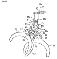
- FIG. 4 is a perspective view of the inner lever 81 and a peripheral section thereof. As shown in FIG. 4 , the inner lever 81 is connected to the shift-and-select shaft 5 so as to be incapable of relative rotation and incapable of relative motion in the direction of the axis X1.
- the inner lever 81 is provided with a cylindrically-shaped cylindrical section 81 a externally fitted onto an external peripheral surface of the shift-and-select shaft 5, a base section 81b protruding in a radial direction from an outer circumferential surface of that cylindrical section 81a and having a cross-section extending longitudinally in the direction of the axis X1, and in addition, an engagement section 81c having a thickness in a circumferential direction thinner than the base section 81b, protruding from an outer edge of that base section 81b and having a cross-section extending longitudinally in the direction of the axis X1 in the same way as the base section 81b.
- An interlock member 82 makes sliding contact with both sides of this base section 81b in a circumferential direction thereof.
- a cylindrical section 82a supported so as to be capable of moving in the direction of the axis X1 and rotating around the axis X1 relative to the shift-and-select shaft 5, a pair of rotation transmission members 82b, 82b extending from both ends of an external peripheral surface of that cylindrical section 82a in parallel with each other so as to be opposed, a sliding member 82c extending from that cylindrical section 82a in the axis direction and also sliding on both sides of the base section 81b of the inner lever 81 in a circumferential direction thereof, and a pair of guide members 82d, 82d extending from both sides of this sliding member 82c towards an outer side in a radial direction and also extending in a circumferential direction with an arc shape are provided on this interlock member 82.
- a length of this guide member 82d in the axis direction is substantially equivalent to a length of the engagement section 81c of the inner lever 81 in the direction of the axis X1. Furthermore, a gap between the cylindrical section 81a of the inner lever 81 and the cylindrical section 82a of the interlock member 82 in the direction of the axis X1 is provided such that the inner lever 81 is capable of moving to both sides in the direction of the axis X1.
- FIG. 5 is an arrow view of the inner lever 81 and the interlock member 82 of FIG. 4 seen from the direction of an arrow A parallel to the axis X1 of the shift-and-select shaft 5.
- a select inner lever 21 a provided on the select outer lever 21 is interposed between the mutually opposing pair of rotation transmission members 82b, 82b of the interlock member 82.
- the select inner lever 21a presses in a perpendicular direction with respect to a contact surface 83 of the rotation transmission member 82b in accordance with a select operation force of the select outer lever 21, the interlock member 82 is rotated with the shift-and-select shaft 5 as a center of rotation.
- FIG. 6 is a view of the manual transmission of FIG. 3 seen from the direction of an arrow B parallel to the axis X1.
- an internal perimeter surface of the first shift fork 61 to third shift fork 63 has an arc shape so as to be capable of engaging with a sleeve (not shown in the figure).
- a first shift head 85a. is connected from the first shift fork shaft 51 via a first connection member 85.
- a second shift head 86a is connected from the second shift fork shaft 52 via a second connection member 86
- a third shift head 87a is connected from the third shift fork shaft 53 via a third connection member 87.
- a reverse-use shift head 88 formed on a reverse arm for a reverse stage (not shown in the figure) is disposed adjacent to the first shift head 85a.
- an engagement groove 89 is formed in the first shift head 85a in order to engage with both ends of the engagement section 81 c of the inner lever 81 in the axis direction. Furthermore, a similar engagement groove is also provided on the other shift heads, 86a, 87a, 88.
- the interlock member 82 is rotated with the shift-and-select shaft 5 as a center of rotation due to a select operation of the select outer lever 21, and the rotation thereof is transferred via the guide surfaces 84 of the interlock member 82 to the inner lever 81 in an interlocked manner.
- the third shift stage and the fourth shift stage as shown in FIG.
- the interlock member 82 is rotated with the shift-and-select shaft 5 as the center of rotation due to a select operation of the select outer lever 21, and the rotation thereof is transferred via the guide surfaces 84 of the interlock member 82 to the inner lever 81 in an interlocked manner.
- the first shift stage and the second shift stage it rotates as far as, and is positioned at, a position whereat the engagement section 81c of the inner lever 81 and the first shift head 85a of the first shift fork shaft 51 overlap in the axis direction, or in other words, a position whereat the engagement section 81c engages with the first shift head 85a.
- the first shift head 85a engaged with the engagement section 81c is also similarly moved in the direction of the axis X2.
- a sleeve of a synchro mechanism (not shown in the figure) is moved and the first shift stage gear or the second shift stage gear is established.
- the interlock member 82 is rotated with the shift-and-select shaft 5 as the center of rotation due to a select operation of the select outer lever 21, and the rotation thereof is transferred via the guide surfaces 84 of the interlock member 82 to the inner lever 81 in an interlocked manner.
- the fifth shift stage and the sixth shift stage it rotates as far as, and is positioned at, a position whereat the engagement section 81c of the inner lever 81 and the third shift head 87a of the third shift fork shaft 53 overlap in the axis direction, or in other words, a position whereat the engagement section 81c engages with the third shift head 87a.
- the inner lever 81 is engaged with a reverse arm (not shown in the figure) due to the select operation of the select outer lever 21, and as a result of motion of the reverse arm interlocked with the shift operation of the shift outer lever 31, a reverse idler gear (not shown in the figure) moves and a reverse shift stage is established.
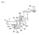
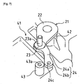
- FIG. 7 and FIG. 8 are perspective views showing the above-mentioned select outer lever 21 and a section of an outer surface of the transmission case 41 in the vicinity thereof.
- the select outer lever 21 is disposed on an upper surface of the transmission case 41, is supported so as to be capable of rotating freely around a vertical axis, and as explained above, performs a rotation operation (select operation) of the shift-and-select shaft 5 by rotating as a result of receiving an operation force of the shift lever 1 via the select cable 2.
- this select outer lever 21 comprises a base section 22 supported on the upper surface of the transmission case 41, a cable connection section 23 whereto the select cable 2 is connected, and a positioning-use arm 24 used in order to perform rotation positioning upon adjustment of the cable length, formed as one.
- the above-mentioned base section 22 is inserted into a boss section 42 formed on the upper surface of the transmission case 41 and is capable of rotation around an axis of this boss section 42. A rotation operation of the shift-and-select shaft 5 is performed pursuant to this rotation.
- connection pin 23a is provided extending vertically upwards on an upper surface of the cable connection section 23, and the above-mentioned select cable 2 is connected to this connection pin 23a (see FIG. 1 ). That is to say, a force of operation in the select direction with respect to the shift lever 1 by the driver is transferred to this connection pin 23a via the select cable 2, and as a result thereof, the select outer lever 21 rotates with the above-mentioned base section 22 as a center of rotation.
- the above-mentioned positioning-use arm 24 is formed continuously from the above-mentioned cable connection section 23 and is provided with a suspension section 24a extending downward towards the upper surface of the transmission case 41 from this cable connection section 23 and a positioning section 24b extending in a horizontal direction from a lower edge of this suspension section 24a.
- an opening 24c is formed at a center of this positioning section 24b passing through in a vertical direction. In a plan view, this opening 24c has a circular shape.
- a positioning boss 43 used upon positioning of a rotation position of the above-mentioned select outer lever 21 is provided on the upper surface of the transmission case 41.
- a position of formation of this positioning boss 43 corresponds to a prescribed position on a motion path of the opening 24c formed in the above-mentioned positioning-use arm 24 upon rotation of the above-mentioned select outer lever 21.
- the positioning boss 43 is formed so as to oppose the position of the above-mentioned opening 24c at a rotation position of the select outer lever 21 in a case wherein the shift-and-select shaft 5 is at the first-speed / second-speed select position (Low position).
- an opening 43a having a circular shape in plan view is formed at a central section of this positioning boss 43, and an internal diameter dimension of this opening 43a is approximately consistent with an internal diameter dimension of the opening 24c formed in the above-mentioned positioning-use arm 24.
- FIG. 9 is a cross-sectional view showing a condition wherein the pin 9 is inserted across these openings 24c, 43a.
- a so-called fixing means of the present invention is configured using the above-mentioned positioning-use arm 24, the positioning boss 43, and the pin 9.
- a position of the shift lever 1 (select position) is positioned so as to correspond to this fixing position of the shift-and-select shaft 5.
- the shift lever 1 is positioned at the first-speed / second-speed select position (Low position).
- the shift lever 1 according to this embodiment is provided with a pull collar mechanism as explained above, if a select operation towards the reverse select position is performed without performing a pulling-up operation of the pull collar of this pull collar mechanism, the shift lever 1 becomes positioned at the first-speed / second-speed select position (Low position: referred to as a stopper position in the present invention that is a boundary section between the select position of a forward travel stage and the select position of the reverse travel stage) and operating efficiency is favorable.
- the cable length can be adjusted with both the shift-and-select shaft 5 and the shift lever 1 in a condition of being positioned at the first-speed / second-speed select position (Low position), and therefore, the length of the select cable 2 can be suitably adjusted, and the positional relationship between the shift lever 1 and the select outer lever 21, or in other words, the positional relationship between the shift lever 1 and the shift-and-select shaft 5 can be achieved in a precise and reliable manner.
- the above-mentioned pin 9 is extracted from the openings 24c, 43a and the operation is completed.
- the shift lever 1 and the select outer lever 21 both return to the third-speed / fourth-speed select position (N position) (for example, return to a position as shown in FIG. 7 ). This is because a spring not shown in the figure and applying a spring force for return to the neutral position (N position) is connected to the shift lever 1 and the select outer lever 21.
- length adjustment of the select cable 2 can be suitably carried out without the number of components increasing as it is possible to adjust the cable length while performing a position restriction of the shift-and-select shaft 5 by fixing the select outer lever 21 using the transmission case 41, and in addition, without being affected by looseness occurring between various mechanism components inside the speed change mechanism 4 as position fixing of the shift-and-select shaft 5 is performed outside the speed change mechanism 4 using the select outer lever 21.
- the length of the select cable 2 adjusted in this case be set slightly shorter than the suitable length (shorter within a range wherein erroneous operation of a speed change is not caused to occur).
- the presence of this pin 9 does not increase the weight of the transmission. Furthermore, when compared with a conventional transmission, only addition of the positioning boss 43 to the transmission case 41 and addition of the positioning-use arm 24 to the select outer lever 21 is carried out, and therefore, the weight of the transmission is not greatly increased.
- the present invention is not limited to this, and it can be the third-speed / fourth-speed select position (N position) or the fifth-speed / sixth-speed select position (Low position).
- the pin 9 was used as a tool for performing position fixing of the select outer lever 21 on the transmission case 41, a standard tool such as a screwdriver, etc. can also be used. In such a case, the internal diameter dimension of the openings 24c, 43a must be made consistent with an external diameter dimension of the screwdriver, etc. Furthermore, the pin 9 is not limited to a pin that can be removed from the transmission case 41 and can also be a pin that is mounted on the transmission case 41. As a result thereof, it is possible to prevent loss of the pin 9, and in addition, operation efficiency is improved upon readjustment of the length of the select cable 2.
- the adjustment mechanism for a speed-change cable of a manual transmission of the present invention has a simple configuration, it is possible to reduce weight and achieve low cost, and in addition, it is possible to adjust the length of the speed-change cable with a high degree of precision, providing an advantage in terms of high reliability. Furthermore, it also contributes greatly to operation efficiency in the manufacture of manual transmissions.
Landscapes
- Engineering & Computer Science (AREA)
- General Engineering & Computer Science (AREA)
- Mechanical Engineering (AREA)
- Gear-Shifting Mechanisms (AREA)
Claims (3)
- Einstellmechanismus für ein Gangwechselkabel (2, 3) eines Handschaltgetriebe, das einen von einem Fahrer betätigten Schalthebel (1), einen Schalt- und Auswahlschaft (5), der einen Gangwechselvorgang durch einen Gangwechselmechanismus (4) ermöglicht, der innerhalb eines Getriebegehäuses (41) vorgesehen ist, und einen Außenhebel (21) hat, der außerhalb des Getriebegehäuses (41) vorgesehen ist, der mit dem Schalt-und Auswahlschaft (5) gekoppelt ist und zudem mit dem Schalthebel (1) verbunden ist, um eine Übertragung einer Betätigungskraft über das Gangwechselkabel (2, 3) zu ermöglichen, mit:einer Fixierungseinrichtung (9) zum Fixieren des Schalt-und Auswahlschafts (5) an einer vorgeschriebenen Kabeleinstellstandardstellung (P1) durch Fixieren einer Stellung des Außenhebels (21) auf dem Getriebegehäuse (41),dadurch gekennzeichnet, dassdie Fixierungseinrichtung (9) so gestaltet ist, dass eine Öffnung (24c, 43a) sowohl an dem Außenhebel (21) als auch an dem Getriebegehäuse (41) ausgebildet ist, und die Stellung des Außenhebels (21) an dem Getriebegehäuse (41) fixiert wird, indem diese Öffnungen (24c, 43a) ausgerichtet werden und ein Stift (9) darin eingebracht wird.
- Einstellmechanismus für ein Gangwechselkabel eines Handschaltgetriebes von Anspruch 1, wobei:der Schalthebel (1) mit einem Rückwärtsbetätigungsmechanismus vorgesehen ist, der infolge einer Auswahlbetätigung von einer Auswahlstellung (P1, P2, P3) einer Vorwärtsfahrstufe zu einer Auswahlstellung einer Rückwärtsfahrstufe betätigt wird, und die Auswahlstellung (P4) für die Rückwärtsfahrstufe unabhängig von der Auswahlstellung für die Vorwärtsfahrstufe in einer Auswahlrichtung (X) dieser vorgesehen ist.
- Einstellmechanismus für ein Gangwechselkabel eines Handschaltgetriebes von Anspruch 2, wobei:die Kabeleinstellstandardstellung (P1) des Schalt- und Auswahlschafts (5), der durch die Fixierungseinrichtung (9) fixiert ist, ein Grenzabschnitt der Auswahlstellung (P1, P2, P3) für die Vorwärtsfahrstufe und der Auswahlstellung (P4) für die Rückwärtsfahrstufe in der Auswahlrichtung (X) des Schalthebels (1) ist.
Applications Claiming Priority (2)
| Application Number | Priority Date | Filing Date | Title |
|---|---|---|---|
| JP2007247003A JP2009079601A (ja) | 2007-09-25 | 2007-09-25 | 手動変速機の変速用ケーブル調整機構 |
| PCT/JP2008/002339 WO2009040985A1 (en) | 2007-09-25 | 2008-08-28 | Adjustment mechanism for a speed-change cable of a manual transmission |
Publications (2)
| Publication Number | Publication Date |
|---|---|
| EP2203665A1 EP2203665A1 (de) | 2010-07-07 |
| EP2203665B1 true EP2203665B1 (de) | 2011-10-05 |
Family
ID=40011363
Family Applications (1)
| Application Number | Title | Priority Date | Filing Date |
|---|---|---|---|
| EP08834626A Not-in-force EP2203665B1 (de) | 2007-09-25 | 2008-08-28 | Mechanismus zur einstellung eines geschwindigkeitsänderungskabels eines manuellen getriebes |
Country Status (5)
| Country | Link |
|---|---|
| EP (1) | EP2203665B1 (de) |
| JP (1) | JP2009079601A (de) |
| CN (1) | CN101802461A (de) |
| AT (1) | ATE527476T1 (de) |
| WO (1) | WO2009040985A1 (de) |
Families Citing this family (9)
| Publication number | Priority date | Publication date | Assignee | Title |
|---|---|---|---|---|
| JP4596042B2 (ja) * | 2008-06-02 | 2010-12-08 | トヨタ自動車株式会社 | 車両用手動変速機 |
| GB201014706D0 (en) | 2010-09-03 | 2010-10-20 | Nexeon Ltd | Porous electroactive material |
| KR101846556B1 (ko) * | 2012-05-02 | 2018-05-18 | 현대자동차주식회사 | 수동변속기의 변속레버 조작력 전달장치 |
| KR101393985B1 (ko) * | 2012-12-06 | 2014-05-12 | 현대자동차주식회사 | 수동변속기의 변속레버 조작력 전달장치 |
| JP6115141B2 (ja) * | 2013-01-17 | 2017-04-19 | マツダ株式会社 | 手動変速機 |
| KR101601560B1 (ko) * | 2014-12-22 | 2016-03-08 | 현대자동차주식회사 | 가변-반경 레버 구조 |
| FR3045765B1 (fr) * | 2015-12-22 | 2018-01-19 | Psa Automobiles Sa. | Boite de vitesses pour un vehicule automobile equipee d'une piece d'immobilisation provisoire du levier de commande de cette boite |
| JP6595412B2 (ja) * | 2016-07-29 | 2019-10-23 | アイシン・エィ・ダブリュ株式会社 | 手動式変速機のケーブル調整装置 |
| CN108372848B (zh) * | 2018-03-06 | 2020-05-29 | 贵安新区新特电动汽车工业有限公司 | 一种驻车拉线的调整方法 |
Family Cites Families (6)
| Publication number | Priority date | Publication date | Assignee | Title |
|---|---|---|---|---|
| JPH0352465A (ja) * | 1989-07-20 | 1991-03-06 | Sanyo Electric Co Ltd | テレビジヨン受像機 |
| DE4441826C2 (de) * | 1993-12-02 | 1997-09-18 | Volkswagen Ag | Vorrichtung und Verfahren zur Einstellung einer Getriebeschaltung in einem Kraftfahrzeug |
| DE4441138C2 (de) * | 1994-11-18 | 1996-09-19 | Juergen Decker | Fixierstift für ein Getriebe-Betätigungsorgan |
| JP4712206B2 (ja) * | 2001-03-16 | 2011-06-29 | ナイルス株式会社 | インヒビタースイッチの位置決め方法、位置決め構造 |
| KR100559387B1 (ko) * | 2003-10-01 | 2006-03-10 | 현대자동차주식회사 | 변속기의 변속 제어장치 |
| FR2885981B1 (fr) * | 2005-05-20 | 2007-08-17 | Peugeot Citroen Automobiles Sa | Dispositif de blocage provisoire d'un levier de selection et de passage de vitesses d'une boite de vitesse d'un vehicule automobile |
-
2007
- 2007-09-25 JP JP2007247003A patent/JP2009079601A/ja active Pending
-
2008
- 2008-08-28 WO PCT/JP2008/002339 patent/WO2009040985A1/en not_active Ceased
- 2008-08-28 CN CN200880107816A patent/CN101802461A/zh active Pending
- 2008-08-28 AT AT08834626T patent/ATE527476T1/de not_active IP Right Cessation
- 2008-08-28 EP EP08834626A patent/EP2203665B1/de not_active Not-in-force
Also Published As
| Publication number | Publication date |
|---|---|
| JP2009079601A (ja) | 2009-04-16 |
| WO2009040985A1 (en) | 2009-04-02 |
| CN101802461A (zh) | 2010-08-11 |
| ATE527476T1 (de) | 2011-10-15 |
| EP2203665A1 (de) | 2010-07-07 |
Similar Documents
| Publication | Publication Date | Title |
|---|---|---|
| EP2203665B1 (de) | Mechanismus zur einstellung eines geschwindigkeitsänderungskabels eines manuellen getriebes | |
| US8505403B2 (en) | Gear shifting actuator and method of shifting gear ratios | |
| EP2180213B1 (de) | Schaltgetriebe | |
| JP5630578B2 (ja) | 車両用手動変速機の操作機構 | |
| CN101592223B (zh) | 用于变速器的换档机构 | |
| US8056433B2 (en) | Shifting device for a manual transmission of a vehicle | |
| CN102322519A (zh) | 双离合器自动变速箱的换挡执行机构 | |
| KR101519229B1 (ko) | 수동변속기 오조작 방지 장치 | |
| CN104976343A (zh) | 致动器组件 | |
| JP2005090621A (ja) | 手動変速機のリバースミスシフト防止装置 | |
| EP3249265B1 (de) | Schaltgabelmodul | |
| JP5092993B2 (ja) | 手動変速機 | |
| EP4224039B1 (de) | Fahrzeuggetriebe | |
| KR101181049B1 (ko) | 듀얼클러치 변속기의 변속장치 | |
| JP4683076B2 (ja) | 変速機 | |
| EP2559919A1 (de) | Gangschaltungsanordnung für ein Fahrzeug | |
| JP5344185B2 (ja) | 変速装置 | |
| EP3069054B1 (de) | Handschaltgetriebe | |
| KR100642547B1 (ko) | 수동변속기의 변속조작기구 | |
| JP6038176B2 (ja) | 変速操作装置 | |
| JP2011174525A (ja) | 手動変速機 |
Legal Events
| Date | Code | Title | Description |
|---|---|---|---|
| PUAI | Public reference made under article 153(3) epc to a published international application that has entered the european phase |
Free format text: ORIGINAL CODE: 0009012 |
|
| 17P | Request for examination filed |
Effective date: 20100120 |
|
| AK | Designated contracting states |
Kind code of ref document: A1 Designated state(s): AT BE BG CH CY CZ DE DK EE ES FI FR GB GR HR HU IE IS IT LI LT LU LV MC MT NL NO PL PT RO SE SI SK TR |
|
| AX | Request for extension of the european patent |
Extension state: AL BA MK RS |
|
| 17Q | First examination report despatched |
Effective date: 20101012 |
|
| DAX | Request for extension of the european patent (deleted) | ||
| GRAP | Despatch of communication of intention to grant a patent |
Free format text: ORIGINAL CODE: EPIDOSNIGR1 |
|
| GRAS | Grant fee paid |
Free format text: ORIGINAL CODE: EPIDOSNIGR3 |
|
| GRAA | (expected) grant |
Free format text: ORIGINAL CODE: 0009210 |
|
| AK | Designated contracting states |
Kind code of ref document: B1 Designated state(s): AT BE BG CH CY CZ DE DK EE ES FI FR GB GR HR HU IE IS IT LI LT LU LV MC MT NL NO PL PT RO SE SI SK TR |
|
| REG | Reference to a national code |
Ref country code: GB Ref legal event code: FG4D |
|
| REG | Reference to a national code |
Ref country code: CH Ref legal event code: EP |
|
| REG | Reference to a national code |
Ref country code: IE Ref legal event code: FG4D |
|
| REG | Reference to a national code |
Ref country code: DE Ref legal event code: R096 Ref document number: 602008010283 Country of ref document: DE Effective date: 20111208 |
|
| REG | Reference to a national code |
Ref country code: NL Ref legal event code: VDEP Effective date: 20111005 |
|
| PG25 | Lapsed in a contracting state [announced via postgrant information from national office to epo] |
Ref country code: SI Free format text: LAPSE BECAUSE OF FAILURE TO SUBMIT A TRANSLATION OF THE DESCRIPTION OR TO PAY THE FEE WITHIN THE PRESCRIBED TIME-LIMIT Effective date: 20111005 |
|
| LTIE | Lt: invalidation of european patent or patent extension |
Effective date: 20111005 |
|
| REG | Reference to a national code |
Ref country code: AT Ref legal event code: MK05 Ref document number: 527476 Country of ref document: AT Kind code of ref document: T Effective date: 20111005 |
|
| PG25 | Lapsed in a contracting state [announced via postgrant information from national office to epo] |
Ref country code: LT Free format text: LAPSE BECAUSE OF FAILURE TO SUBMIT A TRANSLATION OF THE DESCRIPTION OR TO PAY THE FEE WITHIN THE PRESCRIBED TIME-LIMIT Effective date: 20111005 Ref country code: NO Free format text: LAPSE BECAUSE OF FAILURE TO SUBMIT A TRANSLATION OF THE DESCRIPTION OR TO PAY THE FEE WITHIN THE PRESCRIBED TIME-LIMIT Effective date: 20120105 Ref country code: BE Free format text: LAPSE BECAUSE OF FAILURE TO SUBMIT A TRANSLATION OF THE DESCRIPTION OR TO PAY THE FEE WITHIN THE PRESCRIBED TIME-LIMIT Effective date: 20111005 Ref country code: IS Free format text: LAPSE BECAUSE OF FAILURE TO SUBMIT A TRANSLATION OF THE DESCRIPTION OR TO PAY THE FEE WITHIN THE PRESCRIBED TIME-LIMIT Effective date: 20120205 |
|
| PG25 | Lapsed in a contracting state [announced via postgrant information from national office to epo] |
Ref country code: HR Free format text: LAPSE BECAUSE OF FAILURE TO SUBMIT A TRANSLATION OF THE DESCRIPTION OR TO PAY THE FEE WITHIN THE PRESCRIBED TIME-LIMIT Effective date: 20111005 Ref country code: NL Free format text: LAPSE BECAUSE OF FAILURE TO SUBMIT A TRANSLATION OF THE DESCRIPTION OR TO PAY THE FEE WITHIN THE PRESCRIBED TIME-LIMIT Effective date: 20111005 Ref country code: LV Free format text: LAPSE BECAUSE OF FAILURE TO SUBMIT A TRANSLATION OF THE DESCRIPTION OR TO PAY THE FEE WITHIN THE PRESCRIBED TIME-LIMIT Effective date: 20111005 Ref country code: PT Free format text: LAPSE BECAUSE OF FAILURE TO SUBMIT A TRANSLATION OF THE DESCRIPTION OR TO PAY THE FEE WITHIN THE PRESCRIBED TIME-LIMIT Effective date: 20120206 Ref country code: SE Free format text: LAPSE BECAUSE OF FAILURE TO SUBMIT A TRANSLATION OF THE DESCRIPTION OR TO PAY THE FEE WITHIN THE PRESCRIBED TIME-LIMIT Effective date: 20111005 Ref country code: GR Free format text: LAPSE BECAUSE OF FAILURE TO SUBMIT A TRANSLATION OF THE DESCRIPTION OR TO PAY THE FEE WITHIN THE PRESCRIBED TIME-LIMIT Effective date: 20120106 |
|
| PG25 | Lapsed in a contracting state [announced via postgrant information from national office to epo] |
Ref country code: CY Free format text: LAPSE BECAUSE OF FAILURE TO SUBMIT A TRANSLATION OF THE DESCRIPTION OR TO PAY THE FEE WITHIN THE PRESCRIBED TIME-LIMIT Effective date: 20111005 |
|
| PG25 | Lapsed in a contracting state [announced via postgrant information from national office to epo] |
Ref country code: CZ Free format text: LAPSE BECAUSE OF FAILURE TO SUBMIT A TRANSLATION OF THE DESCRIPTION OR TO PAY THE FEE WITHIN THE PRESCRIBED TIME-LIMIT Effective date: 20111005 Ref country code: DK Free format text: LAPSE BECAUSE OF FAILURE TO SUBMIT A TRANSLATION OF THE DESCRIPTION OR TO PAY THE FEE WITHIN THE PRESCRIBED TIME-LIMIT Effective date: 20111005 Ref country code: BG Free format text: LAPSE BECAUSE OF FAILURE TO SUBMIT A TRANSLATION OF THE DESCRIPTION OR TO PAY THE FEE WITHIN THE PRESCRIBED TIME-LIMIT Effective date: 20120105 Ref country code: SK Free format text: LAPSE BECAUSE OF FAILURE TO SUBMIT A TRANSLATION OF THE DESCRIPTION OR TO PAY THE FEE WITHIN THE PRESCRIBED TIME-LIMIT Effective date: 20111005 Ref country code: EE Free format text: LAPSE BECAUSE OF FAILURE TO SUBMIT A TRANSLATION OF THE DESCRIPTION OR TO PAY THE FEE WITHIN THE PRESCRIBED TIME-LIMIT Effective date: 20111005 |
|
| PLBE | No opposition filed within time limit |
Free format text: ORIGINAL CODE: 0009261 |
|
| STAA | Information on the status of an ep patent application or granted ep patent |
Free format text: STATUS: NO OPPOSITION FILED WITHIN TIME LIMIT |
|
| PG25 | Lapsed in a contracting state [announced via postgrant information from national office to epo] |
Ref country code: PL Free format text: LAPSE BECAUSE OF FAILURE TO SUBMIT A TRANSLATION OF THE DESCRIPTION OR TO PAY THE FEE WITHIN THE PRESCRIBED TIME-LIMIT Effective date: 20111005 Ref country code: RO Free format text: LAPSE BECAUSE OF FAILURE TO SUBMIT A TRANSLATION OF THE DESCRIPTION OR TO PAY THE FEE WITHIN THE PRESCRIBED TIME-LIMIT Effective date: 20111005 Ref country code: IT Free format text: LAPSE BECAUSE OF FAILURE TO SUBMIT A TRANSLATION OF THE DESCRIPTION OR TO PAY THE FEE WITHIN THE PRESCRIBED TIME-LIMIT Effective date: 20111005 |
|
| 26N | No opposition filed |
Effective date: 20120706 |
|
| REG | Reference to a national code |
Ref country code: DE Ref legal event code: R097 Ref document number: 602008010283 Country of ref document: DE Effective date: 20120706 |
|
| PG25 | Lapsed in a contracting state [announced via postgrant information from national office to epo] |
Ref country code: AT Free format text: LAPSE BECAUSE OF FAILURE TO SUBMIT A TRANSLATION OF THE DESCRIPTION OR TO PAY THE FEE WITHIN THE PRESCRIBED TIME-LIMIT Effective date: 20111005 |
|
| REG | Reference to a national code |
Ref country code: CH Ref legal event code: PL |
|
| PG25 | Lapsed in a contracting state [announced via postgrant information from national office to epo] |
Ref country code: MC Free format text: LAPSE BECAUSE OF NON-PAYMENT OF DUE FEES Effective date: 20120831 |
|
| GBPC | Gb: european patent ceased through non-payment of renewal fee |
Effective date: 20120828 |
|
| PG25 | Lapsed in a contracting state [announced via postgrant information from national office to epo] |
Ref country code: ES Free format text: LAPSE BECAUSE OF FAILURE TO SUBMIT A TRANSLATION OF THE DESCRIPTION OR TO PAY THE FEE WITHIN THE PRESCRIBED TIME-LIMIT Effective date: 20120116 Ref country code: CH Free format text: LAPSE BECAUSE OF NON-PAYMENT OF DUE FEES Effective date: 20120831 Ref country code: LI Free format text: LAPSE BECAUSE OF NON-PAYMENT OF DUE FEES Effective date: 20120831 |
|
| REG | Reference to a national code |
Ref country code: FR Ref legal event code: ST Effective date: 20130430 |
|
| REG | Reference to a national code |
Ref country code: IE Ref legal event code: MM4A |
|
| PG25 | Lapsed in a contracting state [announced via postgrant information from national office to epo] |
Ref country code: FI Free format text: LAPSE BECAUSE OF FAILURE TO SUBMIT A TRANSLATION OF THE DESCRIPTION OR TO PAY THE FEE WITHIN THE PRESCRIBED TIME-LIMIT Effective date: 20111005 |
|
| PG25 | Lapsed in a contracting state [announced via postgrant information from national office to epo] |
Ref country code: DE Free format text: LAPSE BECAUSE OF NON-PAYMENT OF DUE FEES Effective date: 20130301 Ref country code: GB Free format text: LAPSE BECAUSE OF NON-PAYMENT OF DUE FEES Effective date: 20120828 Ref country code: IE Free format text: LAPSE BECAUSE OF NON-PAYMENT OF DUE FEES Effective date: 20120828 |
|
| PG25 | Lapsed in a contracting state [announced via postgrant information from national office to epo] |
Ref country code: FR Free format text: LAPSE BECAUSE OF NON-PAYMENT OF DUE FEES Effective date: 20120831 |
|
| REG | Reference to a national code |
Ref country code: DE Ref legal event code: R119 Ref document number: 602008010283 Country of ref document: DE Effective date: 20130301 |
|
| PG25 | Lapsed in a contracting state [announced via postgrant information from national office to epo] |
Ref country code: MT Free format text: LAPSE BECAUSE OF FAILURE TO SUBMIT A TRANSLATION OF THE DESCRIPTION OR TO PAY THE FEE WITHIN THE PRESCRIBED TIME-LIMIT Effective date: 20111005 |
|
| PG25 | Lapsed in a contracting state [announced via postgrant information from national office to epo] |
Ref country code: TR Free format text: LAPSE BECAUSE OF FAILURE TO SUBMIT A TRANSLATION OF THE DESCRIPTION OR TO PAY THE FEE WITHIN THE PRESCRIBED TIME-LIMIT Effective date: 20111005 |
|
| PG25 | Lapsed in a contracting state [announced via postgrant information from national office to epo] |
Ref country code: LU Free format text: LAPSE BECAUSE OF NON-PAYMENT OF DUE FEES Effective date: 20120828 |
|
| PG25 | Lapsed in a contracting state [announced via postgrant information from national office to epo] |
Ref country code: HU Free format text: LAPSE BECAUSE OF FAILURE TO SUBMIT A TRANSLATION OF THE DESCRIPTION OR TO PAY THE FEE WITHIN THE PRESCRIBED TIME-LIMIT Effective date: 20080828 |