EP2203734B1 - Beleuchrungsvorrichtung und -system zur herstellung und integration kompakter beleuchtungsschemata - Google Patents
Beleuchrungsvorrichtung und -system zur herstellung und integration kompakter beleuchtungsschemata Download PDFInfo
- Publication number
- EP2203734B1 EP2203734B1 EP08807968.6A EP08807968A EP2203734B1 EP 2203734 B1 EP2203734 B1 EP 2203734B1 EP 08807968 A EP08807968 A EP 08807968A EP 2203734 B1 EP2203734 B1 EP 2203734B1
- Authority
- EP
- European Patent Office
- Prior art keywords
- illumination
- illumination apparatus
- intensity
- assembly
- scheme
- Prior art date
- Legal status (The legal status is an assumption and is not a legal conclusion. Google has not performed a legal analysis and makes no representation as to the accuracy of the status listed.)
- Not-in-force
Links
Images


Classifications
-
- G—PHYSICS
- G01—MEASURING; TESTING
- G01N—INVESTIGATING OR ANALYSING MATERIALS BY DETERMINING THEIR CHEMICAL OR PHYSICAL PROPERTIES
- G01N21/00—Investigating or analysing materials by the use of optical means, i.e. using sub-millimetre waves, infrared, visible or ultraviolet light
- G01N21/17—Systems in which incident light is modified in accordance with the properties of the material investigated
- G01N21/1702—Systems in which incident light is modified in accordance with the properties of the material investigated with opto-acoustic detection, e.g. for gases or analysing solids
-
- A—HUMAN NECESSITIES
- A61—MEDICAL OR VETERINARY SCIENCE; HYGIENE
- A61B—DIAGNOSIS; SURGERY; IDENTIFICATION
- A61B5/00—Measuring for diagnostic purposes; Identification of persons
- A61B5/0059—Measuring for diagnostic purposes; Identification of persons using light, e.g. diagnosis by transillumination, diascopy, fluorescence
-
- A—HUMAN NECESSITIES
- A61—MEDICAL OR VETERINARY SCIENCE; HYGIENE
- A61B—DIAGNOSIS; SURGERY; IDENTIFICATION
- A61B5/00—Measuring for diagnostic purposes; Identification of persons
- A61B5/0093—Detecting, measuring or recording by applying one single type of energy and measuring its conversion into another type of energy
- A61B5/0095—Detecting, measuring or recording by applying one single type of energy and measuring its conversion into another type of energy by applying light and detecting acoustic waves, i.e. photoacoustic measurements
-
- A—HUMAN NECESSITIES
- A61—MEDICAL OR VETERINARY SCIENCE; HYGIENE
- A61B—DIAGNOSIS; SURGERY; IDENTIFICATION
- A61B5/00—Measuring for diagnostic purposes; Identification of persons
- A61B5/02—Detecting, measuring or recording for evaluating the cardiovascular system, e.g. pulse, heart rate, blood pressure or blood flow
- A61B5/02007—Evaluating blood vessel condition, e.g. elasticity, compliance
-
- G—PHYSICS
- G01—MEASURING; TESTING
- G01N—INVESTIGATING OR ANALYSING MATERIALS BY DETERMINING THEIR CHEMICAL OR PHYSICAL PROPERTIES
- G01N21/00—Investigating or analysing materials by the use of optical means, i.e. using sub-millimetre waves, infrared, visible or ultraviolet light
- G01N21/17—Systems in which incident light is modified in accordance with the properties of the material investigated
- G01N21/25—Colour; Spectral properties, i.e. comparison of effect of material on the light at two or more different wavelengths or wavelength bands
- G01N21/255—Details, e.g. use of specially adapted sources, lighting or optical systems
-
- G—PHYSICS
- G02—OPTICS
- G02B—OPTICAL ELEMENTS, SYSTEMS OR APPARATUS
- G02B27/00—Optical systems or apparatus not provided for by any of the groups G02B1/00 - G02B26/00, G02B30/00
- G02B27/28—Optical systems or apparatus not provided for by any of the groups G02B1/00 - G02B26/00, G02B30/00 for polarising
- G02B27/283—Optical systems or apparatus not provided for by any of the groups G02B1/00 - G02B26/00, G02B30/00 for polarising used for beam splitting or combining
-
- A—HUMAN NECESSITIES
- A61—MEDICAL OR VETERINARY SCIENCE; HYGIENE
- A61B—DIAGNOSIS; SURGERY; IDENTIFICATION
- A61B2562/00—Details of sensors; Constructional details of sensor housings or probes; Accessories for sensors
- A61B2562/14—Coupling media or elements to improve sensor contact with skin or tissue
- A61B2562/146—Coupling media or elements to improve sensor contact with skin or tissue for optical coupling
-
- G—PHYSICS
- G01—MEASURING; TESTING
- G01N—INVESTIGATING OR ANALYSING MATERIALS BY DETERMINING THEIR CHEMICAL OR PHYSICAL PROPERTIES
- G01N21/00—Investigating or analysing materials by the use of optical means, i.e. using sub-millimetre waves, infrared, visible or ultraviolet light
- G01N21/17—Systems in which incident light is modified in accordance with the properties of the material investigated
- G01N2021/178—Methods for obtaining spatial resolution of the property being measured
- G01N2021/1782—In-depth resolution
-
- G—PHYSICS
- G01—MEASURING; TESTING
- G01N—INVESTIGATING OR ANALYSING MATERIALS BY DETERMINING THEIR CHEMICAL OR PHYSICAL PROPERTIES
- G01N21/00—Investigating or analysing materials by the use of optical means, i.e. using sub-millimetre waves, infrared, visible or ultraviolet light
- G01N21/17—Systems in which incident light is modified in accordance with the properties of the material investigated
- G01N2021/178—Methods for obtaining spatial resolution of the property being measured
- G01N2021/1785—Three dimensional
-
- G—PHYSICS
- G01—MEASURING; TESTING
- G01N—INVESTIGATING OR ANALYSING MATERIALS BY DETERMINING THEIR CHEMICAL OR PHYSICAL PROPERTIES
- G01N2201/00—Features of devices classified in G01N21/00
- G01N2201/02—Mechanical
- G01N2201/022—Casings
- G01N2201/0221—Portable; cableless; compact; hand-held
-
- G—PHYSICS
- G01—MEASURING; TESTING
- G01N—INVESTIGATING OR ANALYSING MATERIALS BY DETERMINING THEIR CHEMICAL OR PHYSICAL PROPERTIES
- G01N2201/00—Features of devices classified in G01N21/00
- G01N2201/06—Illumination; Optics
- G01N2201/063—Illuminating optical parts
- G01N2201/0636—Reflectors
-
- G—PHYSICS
- G01—MEASURING; TESTING
- G01N—INVESTIGATING OR ANALYSING MATERIALS BY DETERMINING THEIR CHEMICAL OR PHYSICAL PROPERTIES
- G01N2201/00—Features of devices classified in G01N21/00
- G01N2201/06—Illumination; Optics
- G01N2201/066—Modifiable path; multiple paths in one sample
- G01N2201/0666—Selectable paths; insertable multiple sources
-
- G—PHYSICS
- G01—MEASURING; TESTING
- G01N—INVESTIGATING OR ANALYSING MATERIALS BY DETERMINING THEIR CHEMICAL OR PHYSICAL PROPERTIES
- G01N2291/00—Indexing codes associated with group G01N29/00
- G01N2291/02—Indexing codes associated with the analysed material
- G01N2291/024—Mixtures
- G01N2291/02466—Biological material, e.g. blood
-
- G—PHYSICS
- G01—MEASURING; TESTING
- G01N—INVESTIGATING OR ANALYSING MATERIALS BY DETERMINING THEIR CHEMICAL OR PHYSICAL PROPERTIES
- G01N2291/00—Indexing codes associated with group G01N29/00
- G01N2291/02—Indexing codes associated with the analysed material
- G01N2291/024—Mixtures
- G01N2291/02475—Tissue characterisation
-
- G—PHYSICS
- G01—MEASURING; TESTING
- G01N—INVESTIGATING OR ANALYSING MATERIALS BY DETERMINING THEIR CHEMICAL OR PHYSICAL PROPERTIES
- G01N2291/00—Indexing codes associated with group G01N29/00
- G01N2291/10—Number of transducers
- G01N2291/106—Number of transducers one or more transducer arrays
-
- G—PHYSICS
- G02—OPTICS
- G02B—OPTICAL ELEMENTS, SYSTEMS OR APPARATUS
- G02B6/00—Light guides; Structural details of arrangements comprising light guides and other optical elements, e.g. couplings
- G02B6/24—Coupling light guides
- G02B6/42—Coupling light guides with opto-electronic elements
- G02B6/4201—Packages, e.g. shape, construction, internal or external details
- G02B6/4202—Packages, e.g. shape, construction, internal or external details for coupling an active element with fibres without intermediate optical elements, e.g. fibres with plane ends, fibres with shaped ends, bundles
- G02B6/4203—Optical features
Definitions
- the present disclosure is generally directed towards the field of photoacoustic (PA) imaging. More particularly, exemplary embodiments of the present disclosure are directed towards illumination apparatus and systems for the production of highly compact illumination schemes whereby PA waves are induced. Exemplary embodiments of the present disclosure are also directed towards illumination apparatus and systems for the production of a compact and portable, integrated transducer-illumination array (TIA).
- PA photoacoustic
- US 2003/025842 A1 discloses an optical projection system that distributes light from an illumination source via fiber optic cables to non-imaging morphing collimating optical elements and beam splitting elements.
- US 2004/174591 A1 discloses a lighting device for a microscope comprising at least one observation beam path, in particular a surgical microscope, with an illumination system and a deflection device for deflecting light emitted from the illumination system onto an object to be observed, in particular an eye to be operated on, the deflection device providing an illumination of the object under various illumination angles with regard to the at least one observation beam path, wherein the deflection device comprises two deflection at least partly provided as physical beam splitters.
- Photoacoustic (PA) imaging is a non-invasive medical imaging technique that may be used for detecting vascular and dermatological diseases, e.g., skin and breast cancers.
- the PA effect arises wherein a target sample becomes heated due to absorption of light, producing an increase in pressure and/or volume of the material and its surroundings.
- US waves ultrasonic waves.
- the US waves can ultimately be converted to near-real time two or three-dimensional images of the target sample using various mathematical equations.
- PA imaging provides relatively inexpensive and effective near real-time high-contrast imaging with relatively little danger to the target sample.
- Prior apparatus, systems, and methods for PA imaging generally employ a single low-energy near-infrared laser to illuminate the target sample using a single US transducer. See, for example, “ Optoacoustic Tomography,” Oraevsky and Karabutov, Biomedical Photonics Handbook, P 34-1, 2003, CRC Press LLC , “ Ultrasound-mediated biophotonic imaging: A review of acousto-optical tomography and photo-acoustic tomography," Disease Makers 19, P. 123-138 (2003-2004 ); U.S. Patent Number 4,255,971 to Rosencwaig , "Thermoacoustic Microscopy;" U.S.
- Patent Number 5,070,733 to Nagata and Koda "Photoacoustic Imaging Method;” U.S. Patent Number 5,840,023 to Oraevsky et al. , “Optoacoustic Imaging for Medical Diagnosis;” U.S. Patent Number 6,212,421 to Vo-Dinh et al. , “Method and Apparatus of Spectro-Acoustically Enhanced Ultrasonic Detection for Diagnostics;” U.S. Patent Number 5,977,538 to Unger and Wu , “Optoacoustic Imaging System;” U.S. Patent Number 6,979,292 to Kanayama et al.
- Patent Number 4,576,436 to Daniel discloses a light distribution assembly, comprising beam splitting mirrors, which operates effectively to distribute light that originates as a substantially parallel beam into a uniform pattern.
- illumination apparatus and systems are needed that produce/provide compact illumination schemes.
- illumination apparatus and systems are needed that produce/provide compact illumination schemes of controllable patterns and/or geometries. Indeed, production of dynamically controllable illumination schemes would be particularly advantageous.
- an illumination apparatus for production of compact lightning shemes in particular for photoacoustic imaging, as claimed in claim 1.
- Exemplary embodiments of the disclosed illumination apparatus and systems provide simple, effective and compact means for controllably illuminating a target sample for photoacoustic (PA) imaging purposes.
- PA photoacoustic
- exemplary embodiments and implementations of the present disclosure generally relate to PA imaging, it is specifically contemplated that the disclosed illumination apparatus and systems apply to any field where compact illumination schemes may be used.
- Exemplary embodiments of the presently disclosed apparatus/system generally include at least one lighting source and a beam splitting assembly.
- the at least one lighting source may include a laser optically configured to produce a concentrated beam of electromagnetic waves (e.g., visible or infrared light) of a desired intensity and wavelength.
- a wavelength in the near-infrared range is often desirable.
- the near-infrared wavelengths suffer less absorption and increased penetration deeper into a target sample, resulting in a larger radiated area and, vomtly, greater depths.
- the intensity of the laser beam is kept well within the required limits set by the official standards (ANSI limits).
- the beamsplitting assembly generally includes a sequence of one or more beamsplitters, e.g., beamsplitter cubes, dicroic mirrored prisms, half silvered mirrors, dielectric optical coated mirrors and/or polarizers, such as Wollaston prisms.
- the sequence of one or more beamsplitters is configured such that the source beam for a subsequent beamsplitter is one of the resulting beams from a preceding beamsplitter.
- each intermediate beamsplitter produces (i) a source beam for the subsequent beamsplitter, and (ii) an illumination beam.
- branched configurations may likewise be employed, i.e., wherein a beamsplitter produces source beams for more than one subsequent beamsplitter. Therefore, in general, each disclosed beamsplitter produces at least two resultant beams including any combination of (i) one or more source beams for subsequent beamsplitters and/or (ii) one or more illumination beams.
- transmit-reflect ratios are assigned to each beam splitter.
- Transmit-reflect ratios are relative measures of intensity and are defined, for purposes of the present disclosure, as the intensity of the light transmitted divided by the intensity of the light reflected (i.e., the intensity of a resulting source beam divided by the intensity of a resulting illumination beam).
- the transmit-reflect ratio is calculated for each resultant beam as the intensity of a particular resultant beam divided by the summed intensities of the remaining resultant beams.
- transmit-reflect ratios can be used according to the present disclosure to calculate the relative intensities for each illumination beam in an entire sequence of one or more beamsplitters.
- the beamsplitting assembly may include at least one polarizing beamsplitter.
- the at least one polarizing beamsplitter e.g., Wollaston prism
- the intensity and polarization of resultant beams can be predictably controlled by properly configuring the polarizing beamsplitter. It is noted that, for a polarizing beamsplitter, the degree of polarization of the source beam is an essential element in determining the relative intensities of the resultant beams.
- the beamsplitting assembly may include at least one polarizing beamsplitter that includes a dynamically switchable polarization material that supports and/or facilitates dynamic control of the resultant beam intensities and/or polarizations.
- the transmit-reflect ratios and/or sequence configurations of the one or more beamsplitters are selected and/or designed such that the resulting illumination beams are of desired intensities and/or are arranged in desired patterns/geometries, e.g., four illumination beams of increasing intensity arranged in line.
- the polarization of particular illumination beams can be similarly controlled.
- the resultant beam intensities, geometrical arrangement and/or degrees of polarization can likewise be dynamically controlled.
- the illumination apparatus and systems of the present disclosure advantageously provide adaptable imaging system that can be configured in near-real time for particular image requirements, e.g., scanning depth, sample material, etc.
- Direction-altering mirror assemblies may also be utilized prior to, during or after the beamsplitting process to alter the path of a beam and thus affect a particular pattern/geometry and/or assist in compacting the overall apparatus/system.
- Exemplary embodiments generally include: (1) one or more illumination apparatus for production of compact lighting schemes (i.e., illumination component(s)), (2) an ultrasonic (US) transducer assembly, and (3) means for coupling the illumination component(s) and US transducer assembly with a target sample.
- Coupling means/techniques may include, but are not limited to, use of (i) a US gel pad, e.g., a transparent ultrasound coupling pad, (ii) a container encasing the transducer assembly and illumination component(s) in coupling fluid, and/or (iii) US coupling gel.
- the disclosed illumination apparatus may act to illuminate specific regions of the target sample probing a desired region of interest for the PA effect.
- the resulting US waves emanating from the target sample are then detected using the disclosed transducer assembly.
- the disclosed apparatus/system may be integrated into a larger system, e.g., whereby data from the transducer assembly may be used to create two or three-dimensional images of the target sample.
- an additional feedback loop may be added using the image data to optimize the lighting, e.g., in embodiments/implementations where dynamic control is provided and/or facilitated.
- the at least one lighting source disclosed herein need not be part of an actual transducer assembly/illumination apparatus complex. Rather, the at least one lighting source, e.g., a laser, can be housed elsewhere, i.e., remote from the transducer/illumination complex, with the source beam introduced into the illumination apparatus via fiberoptics or other electromagnetic wave conduction mechanisms.
- the waveguide fiber may be advantageously tapered into the beam splitting assembly and encased therewith or otherwise bonded with respect thereto.
- the disclosed illumination apparatus may be positioned relative to the transducer assembly such that the area and/or the target sample positioned directly under the transducer assembly is illuminated.
- a light reflecting layer e.g., a mirror or foil, may be positioned between the transducer assembly and the target sample.
- the reflective layer generally acts to minimize electromagnetic wave dissipation from the sample and illuminating the transducer.
- the reflective layer may be coupled with one or more direction-altering mirror assemblies in order to minimize the distance between the transducer assembly and the target sample and/or to compact the system.
- illumination beams emanating from the illumination apparatus could be reflected off of a mirror positioned directly below the illumination apparatus, e.g., wherein the mirror is angled such that the illumination beams are then reflected off of a second mirror and/or reflective layer toward the area of the target sample directly under the transducer assembly.
- the disclosed illumination apparatus and systems provide means for producing and/or integrating compact lighting schemes. Indeed, exemplary embodiments of the present disclosure produce compact illumination schemes of dynamically controllable intensity, polarization, patterns and/or geometries and integrate such illumination schemes with one or more ultrasonic (US) transducers/ultrasonic transducer arrays.
- US ultrasonic
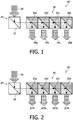
- an exemplary apparatus for the production of compact lighting schemes (illumination apparatus) 10 is depicted that includes a single light source 20 and a beamsplitting assembly 30 of four non-polarizing beamsplitters 32a, 32b, 32c, and 32d with varying transmission-reflection(T/R) coefficients.
- the light source 20 is directed into the beamsplitting assembly 30 using a direction-altering mirror assembly 24 that includes a single angled mirror 22.
- the intensity of the resultant illumination beams 34a, 34b, 34c, and 34d is determined by the T/R coefficients.
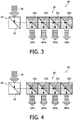
- Figures 2-4 depict exemplary intensity configurations of the illumination beams 34a, 34b, 34c, and 34d for the exemplary apparatus 10 depicted in Figure 1 . More specifically, Figure 2 depicts a uniform intensity scheme, which does not fall within the scope of appended claim 1, Figure 3 depicts a center focused intensity scheme, and Figure 4 depicts a graduated intensity scheme. Each scheme is produced by using the correct T/R ratio for each beamsplitter 32a, 32b, 32c, and 32d.
- T/R ratios assuming a source beam 20 intensity of 100
- T/R for beamsplitter 32a 75/25
- T/R for beamsplitter 32b 50/25
- T/R for beamsplitter 32c 25/25
- T/R for beamsplitter 32d 0/25.
- the physical effect of these coefficients is that, for example, beamsplitter 32a produces a resultant illumination beam with an intensity of 25 and a resultant source beam for beamsplitter 32b with an intensity of 75.
- T/R ratios for the illumination schemes depicted in Figure 3 and Figure 4 can be calculated (once again assuming a source beam 20 intensity of 100) as follows: for the center focused intensity scheme (90/10, 50/40, 10/40, 0/10) and for the graduated intensity scheme (90/10, 70/20, 40/30, 0/40) (where the ratios are presented as T/R for beamsplitter 32a, T/R for beamsplitter 32b, T/R for beamsplitter 32c, T/R for beamsplitter 32d, respectively).
- the final beamsplitter 32d effectively acts as a perfect mirror reflecting all the remaining light, such beamsplitter 32d may be replaced with a mirror assembly according to the exemplary implementation depicted therein.
- an exemplary illumination apparatus 15 that includes a single light source 20 and a beamsplitting assembly 30 that includes two polarizing beamsplitters 40a and 40b with varying polarization effects.
- the light source 20 is a homogonous non-polarized laser; however, alternative sources/polarizations may be utilized.
- the polarization of the source light 20 is an essential element in determining the intensity and/or polarization of the resultant illumination beams 42a and 42b.
- the polarization of the source light 20 may be altered to dynamically and controllably effect a change in the resultant lighting scheme.
- the second polarizing beamsplitter 40b effectively acts as a perfect mirror reflecting all the remaining light and may accordingly be replaced with a mirror assembly.
- Figure 6 depicts an exemplary embodiment of the illumination apparatus 15 depicted in Figure 5 , which does not fall within the scope of appended claim 1, wherein an unpolarized light source 20 is passed through the polarizing beamsplitters 40a and 40b in order to produce resultant S and P polarized illumination beams of equal intensity.
- Figures 7-9 depict various embodiments of systems for integrating compact lighting schemes of the present disclosure with a transducer/transducer array.
- the disclosed systems include (1) one or more illumination apparatus for the production of compact lighting schemes (i.e., illumination component(s)/apparatus) 56, (2) an ultrasonic (US) transducer assembly 50, and (3) means for coupling the one or more illumination component(s) 56 and US transducer assembly 50 with a target sample 70.
- the target sample 70 is a dermis layer of live patient wherein subsurface blood vessels 72 are being investigated for vascular disease.
- the source beams for the illumination apparatus are introduced into the system via fiberoptic lines 52.
- the waveguide fiber 52 is tapered into the illumination apparatus 56 and encased therewith.
- the disclosed systems 2, 4 and 6, respectively are integrated into a larger system whereby data from the transducer assembly 50 is transmitted to a processing device 54, e.g., a computer, and used to create two or three-dimensional images of the target sample 70.
- the disclosed means for coupling illumination component(s) and US transducer assembly may include, but is not limited to, use of a US gel pad, use of a container encasing the transducer assembly and illumination apparatus in coupling fluid, and/or US coupling gel.
- Figure 7 depicts the use of a transparent ultrasound gel coupling pad 60 as the means for coupling the illumination apparatus 56 and the transducer assembly 50 with the target sample 70.
- Figure 8 and Figure 9 depict the combined use of a container 62 of coupling fluid and a layer of US coupling gel 64 as means for coupling the exemplary system 4 with the target sample 70. It is noted that, in the particular embodiments depicted in Figure 8 and Figure 9 , the illumination apparatus 56 and part of the transducer assembly 50 are encased in the container 62.
- the illumination apparatus 56 is positioned relative to the transducer assembly 50 such that the area and/or the target sample 70 positioned directly under the transducer assembly 50 is illuminated.
- a reflective layer 68 is coupled with direction-altering mirrors 66 in order to minimize the distance between the transducer assembly 50 and the target sample 70, thus compacting the system 6.
- the illumination beams emanating from the illumination apparatus 56 are first reflected off the mirrors 66 and then reflected off the reflective layer 68 toward the area of the target sample 70 directly under the transducer assembly 50.
- a reflective layer may also be used as depicted in Figure 7 to counteract the dissipation of electromagnetic waves from the sample.
- the illumination beams emanating from the illumination apparatus 56 are further concentrated on the target sample 70 by means of the reflective layer 58 positioned under and adjacent to the transducer assembly 50.
Landscapes
- Health & Medical Sciences (AREA)
- Life Sciences & Earth Sciences (AREA)
- Physics & Mathematics (AREA)
- Pathology (AREA)
- General Health & Medical Sciences (AREA)
- Public Health (AREA)
- General Physics & Mathematics (AREA)
- Veterinary Medicine (AREA)
- Animal Behavior & Ethology (AREA)
- Surgery (AREA)
- Molecular Biology (AREA)
- Medical Informatics (AREA)
- Heart & Thoracic Surgery (AREA)
- Biophysics (AREA)
- Engineering & Computer Science (AREA)
- Biomedical Technology (AREA)
- Biochemistry (AREA)
- Analytical Chemistry (AREA)
- Immunology (AREA)
- Chemical & Material Sciences (AREA)
- Spectroscopy & Molecular Physics (AREA)
- Acoustics & Sound (AREA)
- Optics & Photonics (AREA)
- Vascular Medicine (AREA)
- Cardiology (AREA)
- Physiology (AREA)
- Investigating Or Analyzing Materials By The Use Of Ultrasonic Waves (AREA)
- Ultra Sonic Daignosis Equipment (AREA)
- Investigating Or Analysing Materials By Optical Means (AREA)
Claims (15)
- Beleuchtungsvorrichtung (10, 15) zur Herstellung kompakter Beleuchtungsschemata, umfassend:mindestens eine Lichtquelle (20), die konfiguriert ist, um einen Beleuchtungsstrahl bereitzustellen, undeine Strahlenteilerbaugruppe (30), die eine Sequenz von Strahlenteilern (32, 34) von unterschiedlichen Durchlass-Reflektions-Verhältnissen umfasst, wobei ein Durchlass-Reflektions-Verhältnis die Intensität des durchgelassenen Lichts dividiert durch die Intensität des reflektierten Lichts ist, wobei die Sequenz von Strahlenteilern derartig konfiguriert ist, dass ein Quellenstrahl für einen nachfolgenden Strahlenteiler der Sequenz einer der resultierenden Strahlen aus einem vorhergehenden Strahlenteiler der Sequenz ist; undwobei der Beleuchtungsstrahl von der mindestens einen Lichtquelle vorgesehen ist, um die Strahlenteilerbaugruppe zu durchqueren, und wobei die Strahlenteilerbaugruppe konfiguriert ist, um den Beleuchtungsstrahl der mindestens einen Lichtquelle in Strahlen (34a, 34b, 34c, 34d; 42a, 42b) von gewünschter Intensität aufzuteilen, um ein Beleuchtungsschema ausgewählt aus der Gruppe bestehend aus einem zentrumfokussierten Intensitätsschema und einem abgestuften Intensitätsschema bereitzustellen.
- Beleuchtungsvorrichtung nach Anspruch 1, wobei der Beleuchtungsstrahl der mindestens einen Lichtquelle (20) vorgesehen ist, um vor, während oder nach dem Strahlenteilungsprozess eine oder mehrere richtungsändernde Spiegelbaugruppen (22, 66) zu durchqueren.
- Beleuchtungsvorrichtung nach Anspruch 1, wobei die Sequenz von Strahlenteilern (32, 40) mindestens einen polarisierenden Strahlenteiler (40a, 40b) umfasst.
- Beleuchtungsvorrichtung nach Anspruch 3, wobei der mindestens eine polarisierende Strahlenteiler (40a, 40b) ein polarisierender Strahlenteiler ist, der vorgesehen ist, um den Beleuchtungsstrahl der mindestens einen Lichtquelle in S- und P-polarisierte Strahlen aufzuteilen.
- Beleuchtungsvorrichtung nach Anspruch 3, wobei der mindestens eine polarisierende Strahlenteiler (40a, 40b) dynamisch umschaltbares Polarisationsmaterial umfasst, so dass resultierende Strahlintensitäten und/oder Polarisierungen der Strahlen dynamisch steuerbar sind.
- Beleuchtungsvorrichtung nach Anspruch 1, wobei die Strahlen des Beleuchtungsschemas für photoakustische Bildgebung konfiguriert sind.
- Beleuchtungsvorrichtung nach Anspruch 1, wobei die mindestens eine Lichtquelle einen Laser umfasst, der optisch konfiguriert ist, um einen konzentrierten Strahl von elektromagnetischen Wellen einer gewünschten Intensität und einer gewünschten Wellenlänge zu erzeugen.
- Beleuchtungsvorrichtung nach Anspruch 7, wobei die gewünschte Wellenlänge im nahen Infrarotbereich liegt.
- System (6) zum kompakten Integrieren einer oder mehrerer Beleuchtungsvorrichtungen (10, 15, 56) mit einer Ultraschallwandlerbaugruppe (50), wobei das System Folgendes umfasst:eine oder mehrere Beleuchtungsvorrichtungen (10, 15, 56) nach einem der Ansprüche 1 bis 8;eine Ultraschallwandlerbaugruppe (50) umfassend mindestens einen Ultraschallwandler; wobei die genannte Ultraschallwandlerbaugruppe vorgesehen ist, um in Bezug auf die Zielprobe austretende Ultraschallwellen zu detektieren; undMittel (60, 62, 64) zum Koppeln der einen oder mehreren Beleuchtungsvorrichtungen und der Ultraschallwandlerbaugruppe (50) mit einer Zielprobe (70).
- System nach Anspruch 9, wobei das Mittel zum Koppeln der einen oder mehreren Beleuchtungsvorrichtungen (10, 15, 56) und der Ultraschallwandlerbaugruppe (50) mit der Zielprobe (70) ein Ultraschall-Gelkissen (60), oder einen Behälter mit Kopplungsfluid (62) und einer Schicht aus Ultraschallgel (64), oder ein kompaktes Gehäuse (62) und eine Schicht aus Ultraschallgel (64) umfasst.
- System nach Anspruch 9, wobei die Ultraschallwandlerbaugruppe ein Wandlerarray umfasst.
- System nach Anspruch 9, wobei weiterhin, wenn das Beleuchtungsschema ein zentrumfokussiertes Intensitätsschema umfasst, die eine oder mehrere Beleuchtungsvorrichtungen zwei Beleuchtungsvorrichtungen umfassen, wobei die Strahlenteilerbaugruppe jeder Beleuchtungsvorrichtung eine Sequenz von vier Strahlenteilern umfasst, und wobei das zentrumfokussierte Intensitätsschema Intensitäten von 10, 40, 40 und 10 von 100 Prozent Intensität für jeweilige Strahlenteiler der Strahlenteilerbaugruppe umfasst.
- System nach Anspruch 9, wobei weiterhin, wenn das Beleuchtungsschema ein abgestuftes Intensitätsschema umfasst, die eine oder mehrere Beleuchtungsvorrichtungen zwei Beleuchtungsvorrichtungen umfassen, wobei die Strahlenteilerbaugruppe jeder Beleuchtungsvorrichtung eine Sequenz von vier Strahlenteilern umfasst, und wobei das abgestufte Intensitätsschema Intensitäten von 10, 20, 30 und 40 von 100 Prozent Intensität für jeweilige Strahlenteiler der Strahlenteilerbaugruppe umfasst.
- System nach Anspruch 9, wobei die eine oder mehrere Beleuchtungsvorrichtungen vorgesehen sind, um die Strahlen von gewünschter Intensität dynamisch zu steuern, um ein Beleuchtungsschema zu erzeugen, das konfiguriert ist, um mit dem mindestens einen Ultraschallwandler der Ultraschallwandlerbaugruppe (50) übereinzustimmen.
- System nach Anspruch 9, weiterhin umfassend eine oder mehrere richtungsändernde Spiegelbaugruppen (66) und eine mit der einen oder mehreren richtungsändernden Spiegelbaugruppen (66) gekoppelte reflektierende Schicht (68), wobei die reflektierende Schicht direkt unter der Ultraschallwandlerbaugruppe (50) positioniert ist, wobei die eine oder mehrere richtungsändernde Spiegelbaugruppen (66) (i) direkt unter einer jeweiligen Strahlenteilerbaugruppe der einen oder mehreren Beleuchtungsvorrichtungen (10, 15, 56) und (ii) unter der Ultraschallwandlerbaugruppe (50) positioniert sind, und wobei die eine oder mehrere richtungsändernde Spiegelbaugruppen (66) derartig gewinkelt sind, dass die Strahlen von gewünschter Intensität, die aus der jeweiligen einen oder mehreren Beleuchtungsvorrichtungen (10, 15, 56) austreten, dann von der reflektierenden Schicht (68) zur Fläche der Zielprobe (70) direkt unter der Wandlerbaugruppe (50) reflektiert werden.
Applications Claiming Priority (2)
| Application Number | Priority Date | Filing Date | Title |
|---|---|---|---|
| US98020707P | 2007-10-16 | 2007-10-16 | |
| PCT/IB2008/054194 WO2009050632A1 (en) | 2007-10-16 | 2008-10-13 | Apparatus, systems and methods for production and integration of compact illumination schemes |
Publications (2)
| Publication Number | Publication Date |
|---|---|
| EP2203734A1 EP2203734A1 (de) | 2010-07-07 |
| EP2203734B1 true EP2203734B1 (de) | 2018-02-21 |
Family
ID=40223769
Family Applications (1)
| Application Number | Title | Priority Date | Filing Date |
|---|---|---|---|
| EP08807968.6A Not-in-force EP2203734B1 (de) | 2007-10-16 | 2008-10-13 | Beleuchrungsvorrichtung und -system zur herstellung und integration kompakter beleuchtungsschemata |
Country Status (5)
| Country | Link |
|---|---|
| US (1) | US8677829B2 (de) |
| EP (1) | EP2203734B1 (de) |
| JP (1) | JP5628038B2 (de) |
| CN (1) | CN101828102B (de) |
| WO (1) | WO2009050632A1 (de) |
Cited By (2)
| Publication number | Priority date | Publication date | Assignee | Title |
|---|---|---|---|---|
| KR20220020957A (ko) * | 2019-07-09 | 2022-02-21 | 트룸프 게엠베하 + 코. 카게 | 공간 분해 광음향을 수행하기 위한 장치 및 방법 |
| WO2025054186A1 (en) * | 2023-09-05 | 2025-03-13 | Qualcomm Incorporated | Multispectral photoacoustic devices |
Families Citing this family (20)
| Publication number | Priority date | Publication date | Assignee | Title |
|---|---|---|---|---|
| WO2010127199A2 (en) * | 2009-05-01 | 2010-11-04 | Visualsonics Inc. | System for photoacoustic imaging and related methods |
| JP5709368B2 (ja) * | 2009-11-04 | 2015-04-30 | キヤノン株式会社 | 生体情報取得装置 |
| US8462329B2 (en) * | 2010-07-30 | 2013-06-11 | Kla-Tencor Corp. | Multi-spot illumination for wafer inspection |
| JP5697615B2 (ja) | 2011-02-07 | 2015-04-08 | 富士フイルム株式会社 | 超音波プローブ |
| JP5959803B2 (ja) * | 2011-05-02 | 2016-08-02 | キヤノン株式会社 | 被検体情報取得装置およびその制御方法 |
| JP5774930B2 (ja) * | 2011-07-21 | 2015-09-09 | 日本電産コパル株式会社 | 肌観察装置 |
| JP5840152B2 (ja) | 2012-02-03 | 2016-01-06 | 富士フイルム株式会社 | プローブ |
| JP5840070B2 (ja) * | 2012-05-08 | 2016-01-06 | 富士フイルム株式会社 | 光音響計測装置および光音響計測装置用プローブ |
| JP2014023914A (ja) * | 2012-06-20 | 2014-02-06 | Fujifilm Corp | プローブ及びその保護カバー |
| JP6049209B2 (ja) * | 2014-01-28 | 2016-12-21 | 富士フイルム株式会社 | 光音響計測用プローブおよびそれを備えた光音響計測装置 |
| JP6464558B2 (ja) * | 2014-03-14 | 2019-02-06 | 株式会社リコー | 光学センサ、光学検査装置、および内部特性推定方法 |
| JP6547188B2 (ja) | 2015-09-17 | 2019-07-24 | 国立大学法人名古屋大学 | 光線過敏検査装置 |
| US11061243B2 (en) | 2016-02-22 | 2021-07-13 | Hitachi High-Tech Corporation | Dichroic-mirror array |
| JP6805845B2 (ja) * | 2017-01-25 | 2020-12-23 | 株式会社Ihi | レーザー超音波探傷装置 |
| US11596313B2 (en) | 2017-10-13 | 2023-03-07 | Arizona Board Of Regents On Behalf Of Arizona State University | Photoacoustic targeting with micropipette electrodes |
| US12161295B2 (en) | 2018-03-16 | 2024-12-10 | Arizona Board Of Regents On Behalf Of Arizona State University | Deep brain stimulation electrode with photoacoustic and ultrasound imaging capabilities |
| US11768182B2 (en) | 2019-04-26 | 2023-09-26 | Arizona Board Of Regents On Behalf Of Arizona State University | Photoacoustic and optical microscopy combiner and method of generating a photoacoustic image of a sample |
| US11975327B2 (en) * | 2019-06-19 | 2024-05-07 | Arizona Board Of Regents On Behalf Of Arizona State University | Integrated container adapter for photoacoustic microscopy |
| US11395714B2 (en) | 2019-11-11 | 2022-07-26 | Dermlite Llc | Medical illuminator with variable polarization |
| CN110644061B (zh) * | 2019-11-14 | 2021-09-10 | 广西立盛茧丝绸有限公司 | 一种自动选茧机 |
Family Cites Families (24)
| Publication number | Priority date | Publication date | Assignee | Title |
|---|---|---|---|---|
| US4255971A (en) | 1978-11-01 | 1981-03-17 | Allan Rosencwaig | Thermoacoustic microscopy |
| JPH0827264B2 (ja) | 1988-09-21 | 1996-03-21 | 工業技術院長 | マルチ変調周波数による光音響撮像方法 |
| JPH0415541A (ja) * | 1990-05-09 | 1992-01-20 | Hitachi Ltd | 粒子計数装置 |
| JP2502443B2 (ja) * | 1991-01-30 | 1996-05-29 | 日本鋼管株式会社 | エリプソメ―タ及びこれを用いた塗布厚制御方法 |
| JP3000729B2 (ja) * | 1991-06-25 | 2000-01-17 | 株式会社日立製作所 | 光音響信号検出方法およびその装置 |
| US5248876A (en) * | 1992-04-21 | 1993-09-28 | International Business Machines Corporation | Tandem linear scanning confocal imaging system with focal volumes at different heights |
| AUPN003894A0 (en) * | 1994-12-13 | 1995-01-12 | Xenotech Research Pty Ltd | Head tracking system for stereoscopic display apparatus |
| JPH08285820A (ja) * | 1995-04-17 | 1996-11-01 | Nippon Steel Corp | レーザー超音波検査装置 |
| US5840023A (en) * | 1996-01-31 | 1998-11-24 | Oraevsky; Alexander A. | Optoacoustic imaging for medical diagnosis |
| GB9704737D0 (en) * | 1997-03-07 | 1997-04-23 | Optel Instr Limited | Biological measurement system |
| US6070093A (en) * | 1997-12-02 | 2000-05-30 | Abbott Laboratories | Multiplex sensor and method of use |
| US5977538A (en) * | 1998-05-11 | 1999-11-02 | Imarx Pharmaceutical Corp. | Optoacoustic imaging system |
| US6212421B1 (en) * | 1999-09-03 | 2001-04-03 | Lockheed Martin Energy Research Corp. | Method and apparatus of spectro-acoustically enhanced ultrasonic detection for diagnostics |
| IL138073A0 (en) | 2000-08-24 | 2001-10-31 | Glucon Inc | Photoacoustic assay and imaging system |
| US6490470B1 (en) * | 2001-06-19 | 2002-12-03 | Optosonics, Inc. | Thermoacoustic tissue scanner |
| CA2452064A1 (en) | 2001-06-26 | 2003-01-03 | Honeywell International Inc. | Projection system utilizing fiber optic illumination |
| JP3766032B2 (ja) * | 2002-02-08 | 2006-04-12 | 独立行政法人科学技術振興機構 | 試料の物理的性質の測定方法 |
| KR100493154B1 (ko) * | 2002-03-20 | 2005-06-03 | 삼성전자주식회사 | 광음향분광학을 이용한 비침습적 생체성분 측정장치 |
| JP4234393B2 (ja) * | 2002-10-31 | 2009-03-04 | 株式会社東芝 | 生体情報計測装置 |
| DE10311000C5 (de) * | 2003-03-06 | 2012-05-10 | Leica Instruments (Singapore) Pte. Ltd. | Beleuchtungseinrichtung für ein Mikroskop |
| JP4406226B2 (ja) * | 2003-07-02 | 2010-01-27 | 株式会社東芝 | 生体情報映像装置 |
| JP4247372B2 (ja) * | 2004-04-02 | 2009-04-02 | 京都電子工業株式会社 | 屈折率測定方法および装置 |
| CN1981189B (zh) * | 2004-07-02 | 2010-10-06 | 皇家飞利浦电子股份有限公司 | 具有多探针的光谱系统 |
| JP2006258739A (ja) * | 2005-03-18 | 2006-09-28 | Fujinon Corp | 光束分岐出力装置および複数光束出力型の測定装置 |
-
2008
- 2008-10-13 EP EP08807968.6A patent/EP2203734B1/de not_active Not-in-force
- 2008-10-13 US US12/738,020 patent/US8677829B2/en not_active Expired - Fee Related
- 2008-10-13 CN CN200880111699.1A patent/CN101828102B/zh not_active Expired - Fee Related
- 2008-10-13 WO PCT/IB2008/054194 patent/WO2009050632A1/en not_active Ceased
- 2008-10-13 JP JP2010529479A patent/JP5628038B2/ja not_active Expired - Fee Related
Cited By (2)
| Publication number | Priority date | Publication date | Assignee | Title |
|---|---|---|---|---|
| KR20220020957A (ko) * | 2019-07-09 | 2022-02-21 | 트룸프 게엠베하 + 코. 카게 | 공간 분해 광음향을 수행하기 위한 장치 및 방법 |
| WO2025054186A1 (en) * | 2023-09-05 | 2025-03-13 | Qualcomm Incorporated | Multispectral photoacoustic devices |
Also Published As
| Publication number | Publication date |
|---|---|
| US8677829B2 (en) | 2014-03-25 |
| EP2203734A1 (de) | 2010-07-07 |
| CN101828102A (zh) | 2010-09-08 |
| US20100229650A1 (en) | 2010-09-16 |
| CN101828102B (zh) | 2014-12-17 |
| JP2011501150A (ja) | 2011-01-06 |
| WO2009050632A1 (en) | 2009-04-23 |
| JP5628038B2 (ja) | 2014-11-19 |
Similar Documents
| Publication | Publication Date | Title |
|---|---|---|
| US8677829B2 (en) | Apparatus, systems and methods for production and integration of compact illumination schemes | |
| US12050201B2 (en) | Multi-focus optical-resolution photoacoustic microscopy with ultrasonic array detection | |
| EP0581871B2 (de) | Vorrichtung für optische abbildung und messung | |
| CN104188625B (zh) | 一种多模态显微成像系统 | |
| US6454761B1 (en) | Laser surgery device and method | |
| JP6794352B2 (ja) | 多芯ファイバー内視鏡 | |
| US7006231B2 (en) | Diffraction grating based interferometric systems and methods | |
| KR102040148B1 (ko) | 파이버 스캐닝 광 프로브 및 이를 채용한 의료 영상 기기 | |
| US7526329B2 (en) | Multiple reference non-invasive analysis system | |
| US11530979B2 (en) | Multifocal photoacoustic microscopy through an ergodic relay | |
| WO2005068973A1 (en) | Photoacoustic sensor | |
| WO2008000078A1 (en) | Compact high resolution imaging apparatus | |
| CN115474907B (zh) | 一种高分辨率的手持式oct成像系统 | |
| US8406835B2 (en) | Probe head for spectroscopic analysis of a fluid | |
| CN108209860A (zh) | 一种反射式共聚焦显微成像系统 | |
| CN206687691U (zh) | 一种反射式共聚焦显微成像系统 | |
| US20240260836A1 (en) | Optical sensor circuit and optical sensing method | |
| CN222425987U (zh) | 光声成像探头及成像系统 | |
| KR20140006157A (ko) | 광 스캐닝 프로브 및 및 이를 채용한 의료 영상 기기 | |
| KR20250157423A (ko) | 혼합 어레이 이미징 프로브 | |
| CN121999993A (zh) | 医学影像显示系统 | |
| JP2007252774A (ja) | 光断層イメージング装置 | |
| RU2020135621A (ru) | Система количественного формирования изображений и ее применение |
Legal Events
| Date | Code | Title | Description |
|---|---|---|---|
| PUAI | Public reference made under article 153(3) epc to a published international application that has entered the european phase |
Free format text: ORIGINAL CODE: 0009012 |
|
| 17P | Request for examination filed |
Effective date: 20100517 |
|
| AK | Designated contracting states |
Kind code of ref document: A1 Designated state(s): AT BE BG CH CY CZ DE DK EE ES FI FR GB GR HR HU IE IS IT LI LT LU LV MC MT NL NO PL PT RO SE SI SK TR |
|
| AX | Request for extension of the european patent |
Extension state: AL BA MK RS |
|
| DAX | Request for extension of the european patent (deleted) | ||
| 17Q | First examination report despatched |
Effective date: 20101228 |
|
| RAP1 | Party data changed (applicant data changed or rights of an application transferred) |
Owner name: KONINKLIJKE PHILIPS N.V. |
|
| GRAP | Despatch of communication of intention to grant a patent |
Free format text: ORIGINAL CODE: EPIDOSNIGR1 |
|
| RIC1 | Information provided on ipc code assigned before grant |
Ipc: A61B 5/00 20060101ALI20170801BHEP Ipc: G01N 29/24 20060101ALN20170801BHEP Ipc: A61B 5/02 20060101ALI20170801BHEP Ipc: G02B 27/28 20060101ALI20170801BHEP Ipc: G01N 21/25 20060101ALI20170801BHEP Ipc: G01N 21/17 20060101AFI20170801BHEP Ipc: G02B 6/42 20060101ALN20170801BHEP |
|
| INTG | Intention to grant announced |
Effective date: 20170907 |
|
| GRAS | Grant fee paid |
Free format text: ORIGINAL CODE: EPIDOSNIGR3 |
|
| GRAA | (expected) grant |
Free format text: ORIGINAL CODE: 0009210 |
|
| AK | Designated contracting states |
Kind code of ref document: B1 Designated state(s): AT BE BG CH CY CZ DE DK EE ES FI FR GB GR HR HU IE IS IT LI LT LU LV MC MT NL NO PL PT RO SE SI SK TR |
|
| REG | Reference to a national code |
Ref country code: GB Ref legal event code: FG4D |
|
| REG | Reference to a national code |
Ref country code: CH Ref legal event code: EP |
|
| REG | Reference to a national code |
Ref country code: DE Ref legal event code: R096 Ref document number: 602008054117 Country of ref document: DE Ref country code: AT Ref legal event code: REF Ref document number: 972284 Country of ref document: AT Kind code of ref document: T Effective date: 20180315 |
|
| REG | Reference to a national code |
Ref country code: IE Ref legal event code: FG4D |
|
| REG | Reference to a national code |
Ref country code: DE Ref legal event code: R084 Ref document number: 602008054117 Country of ref document: DE |
|
| REG | Reference to a national code |
Ref country code: NL Ref legal event code: MP Effective date: 20180221 |
|
| REG | Reference to a national code |
Ref country code: LT Ref legal event code: MG4D |
|
| REG | Reference to a national code |
Ref country code: AT Ref legal event code: MK05 Ref document number: 972284 Country of ref document: AT Kind code of ref document: T Effective date: 20180221 |
|
| PG25 | Lapsed in a contracting state [announced via postgrant information from national office to epo] |
Ref country code: NL Free format text: LAPSE BECAUSE OF FAILURE TO SUBMIT A TRANSLATION OF THE DESCRIPTION OR TO PAY THE FEE WITHIN THE PRESCRIBED TIME-LIMIT Effective date: 20180221 Ref country code: CY Free format text: LAPSE BECAUSE OF FAILURE TO SUBMIT A TRANSLATION OF THE DESCRIPTION OR TO PAY THE FEE WITHIN THE PRESCRIBED TIME-LIMIT Effective date: 20180221 Ref country code: HR Free format text: LAPSE BECAUSE OF FAILURE TO SUBMIT A TRANSLATION OF THE DESCRIPTION OR TO PAY THE FEE WITHIN THE PRESCRIBED TIME-LIMIT Effective date: 20180221 Ref country code: FI Free format text: LAPSE BECAUSE OF FAILURE TO SUBMIT A TRANSLATION OF THE DESCRIPTION OR TO PAY THE FEE WITHIN THE PRESCRIBED TIME-LIMIT Effective date: 20180221 Ref country code: NO Free format text: LAPSE BECAUSE OF FAILURE TO SUBMIT A TRANSLATION OF THE DESCRIPTION OR TO PAY THE FEE WITHIN THE PRESCRIBED TIME-LIMIT Effective date: 20180521 Ref country code: ES Free format text: LAPSE BECAUSE OF FAILURE TO SUBMIT A TRANSLATION OF THE DESCRIPTION OR TO PAY THE FEE WITHIN THE PRESCRIBED TIME-LIMIT Effective date: 20180221 Ref country code: LT Free format text: LAPSE BECAUSE OF FAILURE TO SUBMIT A TRANSLATION OF THE DESCRIPTION OR TO PAY THE FEE WITHIN THE PRESCRIBED TIME-LIMIT Effective date: 20180221 |
|
| PG25 | Lapsed in a contracting state [announced via postgrant information from national office to epo] |
Ref country code: LV Free format text: LAPSE BECAUSE OF FAILURE TO SUBMIT A TRANSLATION OF THE DESCRIPTION OR TO PAY THE FEE WITHIN THE PRESCRIBED TIME-LIMIT Effective date: 20180221 Ref country code: SE Free format text: LAPSE BECAUSE OF FAILURE TO SUBMIT A TRANSLATION OF THE DESCRIPTION OR TO PAY THE FEE WITHIN THE PRESCRIBED TIME-LIMIT Effective date: 20180221 Ref country code: AT Free format text: LAPSE BECAUSE OF FAILURE TO SUBMIT A TRANSLATION OF THE DESCRIPTION OR TO PAY THE FEE WITHIN THE PRESCRIBED TIME-LIMIT Effective date: 20180221 Ref country code: BG Free format text: LAPSE BECAUSE OF FAILURE TO SUBMIT A TRANSLATION OF THE DESCRIPTION OR TO PAY THE FEE WITHIN THE PRESCRIBED TIME-LIMIT Effective date: 20180521 Ref country code: GR Free format text: LAPSE BECAUSE OF FAILURE TO SUBMIT A TRANSLATION OF THE DESCRIPTION OR TO PAY THE FEE WITHIN THE PRESCRIBED TIME-LIMIT Effective date: 20180522 |
|
| REG | Reference to a national code |
Ref country code: FR Ref legal event code: PLFP Year of fee payment: 11 |
|
| PG25 | Lapsed in a contracting state [announced via postgrant information from national office to epo] |
Ref country code: RO Free format text: LAPSE BECAUSE OF FAILURE TO SUBMIT A TRANSLATION OF THE DESCRIPTION OR TO PAY THE FEE WITHIN THE PRESCRIBED TIME-LIMIT Effective date: 20180221 Ref country code: EE Free format text: LAPSE BECAUSE OF FAILURE TO SUBMIT A TRANSLATION OF THE DESCRIPTION OR TO PAY THE FEE WITHIN THE PRESCRIBED TIME-LIMIT Effective date: 20180221 Ref country code: IT Free format text: LAPSE BECAUSE OF FAILURE TO SUBMIT A TRANSLATION OF THE DESCRIPTION OR TO PAY THE FEE WITHIN THE PRESCRIBED TIME-LIMIT Effective date: 20180221 Ref country code: PL Free format text: LAPSE BECAUSE OF FAILURE TO SUBMIT A TRANSLATION OF THE DESCRIPTION OR TO PAY THE FEE WITHIN THE PRESCRIBED TIME-LIMIT Effective date: 20180221 |
|
| REG | Reference to a national code |
Ref country code: DE Ref legal event code: R097 Ref document number: 602008054117 Country of ref document: DE |
|
| PG25 | Lapsed in a contracting state [announced via postgrant information from national office to epo] |
Ref country code: SK Free format text: LAPSE BECAUSE OF FAILURE TO SUBMIT A TRANSLATION OF THE DESCRIPTION OR TO PAY THE FEE WITHIN THE PRESCRIBED TIME-LIMIT Effective date: 20180221 Ref country code: CZ Free format text: LAPSE BECAUSE OF FAILURE TO SUBMIT A TRANSLATION OF THE DESCRIPTION OR TO PAY THE FEE WITHIN THE PRESCRIBED TIME-LIMIT Effective date: 20180221 Ref country code: DK Free format text: LAPSE BECAUSE OF FAILURE TO SUBMIT A TRANSLATION OF THE DESCRIPTION OR TO PAY THE FEE WITHIN THE PRESCRIBED TIME-LIMIT Effective date: 20180221 |
|
| PLBE | No opposition filed within time limit |
Free format text: ORIGINAL CODE: 0009261 |
|
| STAA | Information on the status of an ep patent application or granted ep patent |
Free format text: STATUS: NO OPPOSITION FILED WITHIN TIME LIMIT |
|
| 26N | No opposition filed |
Effective date: 20181122 |
|
| PG25 | Lapsed in a contracting state [announced via postgrant information from national office to epo] |
Ref country code: SI Free format text: LAPSE BECAUSE OF FAILURE TO SUBMIT A TRANSLATION OF THE DESCRIPTION OR TO PAY THE FEE WITHIN THE PRESCRIBED TIME-LIMIT Effective date: 20180221 |
|
| REG | Reference to a national code |
Ref country code: CH Ref legal event code: PL |
|
| GBPC | Gb: european patent ceased through non-payment of renewal fee |
Effective date: 20181013 |
|
| REG | Reference to a national code |
Ref country code: BE Ref legal event code: MM Effective date: 20181031 |
|
| PG25 | Lapsed in a contracting state [announced via postgrant information from national office to epo] |
Ref country code: LU Free format text: LAPSE BECAUSE OF NON-PAYMENT OF DUE FEES Effective date: 20181013 Ref country code: MC Free format text: LAPSE BECAUSE OF FAILURE TO SUBMIT A TRANSLATION OF THE DESCRIPTION OR TO PAY THE FEE WITHIN THE PRESCRIBED TIME-LIMIT Effective date: 20180221 |
|
| REG | Reference to a national code |
Ref country code: IE Ref legal event code: MM4A |
|
| PG25 | Lapsed in a contracting state [announced via postgrant information from national office to epo] |
Ref country code: LI Free format text: LAPSE BECAUSE OF NON-PAYMENT OF DUE FEES Effective date: 20181031 Ref country code: BE Free format text: LAPSE BECAUSE OF NON-PAYMENT OF DUE FEES Effective date: 20181031 Ref country code: CH Free format text: LAPSE BECAUSE OF NON-PAYMENT OF DUE FEES Effective date: 20181031 |
|
| PG25 | Lapsed in a contracting state [announced via postgrant information from national office to epo] |
Ref country code: IE Free format text: LAPSE BECAUSE OF NON-PAYMENT OF DUE FEES Effective date: 20181013 Ref country code: GB Free format text: LAPSE BECAUSE OF NON-PAYMENT OF DUE FEES Effective date: 20181013 |
|
| PG25 | Lapsed in a contracting state [announced via postgrant information from national office to epo] |
Ref country code: MT Free format text: LAPSE BECAUSE OF NON-PAYMENT OF DUE FEES Effective date: 20181013 |
|
| PG25 | Lapsed in a contracting state [announced via postgrant information from national office to epo] |
Ref country code: TR Free format text: LAPSE BECAUSE OF FAILURE TO SUBMIT A TRANSLATION OF THE DESCRIPTION OR TO PAY THE FEE WITHIN THE PRESCRIBED TIME-LIMIT Effective date: 20180221 |
|
| PG25 | Lapsed in a contracting state [announced via postgrant information from national office to epo] |
Ref country code: PT Free format text: LAPSE BECAUSE OF FAILURE TO SUBMIT A TRANSLATION OF THE DESCRIPTION OR TO PAY THE FEE WITHIN THE PRESCRIBED TIME-LIMIT Effective date: 20180221 |
|
| PG25 | Lapsed in a contracting state [announced via postgrant information from national office to epo] |
Ref country code: HU Free format text: LAPSE BECAUSE OF FAILURE TO SUBMIT A TRANSLATION OF THE DESCRIPTION OR TO PAY THE FEE WITHIN THE PRESCRIBED TIME-LIMIT; INVALID AB INITIO Effective date: 20081013 |
|
| PG25 | Lapsed in a contracting state [announced via postgrant information from national office to epo] |
Ref country code: IS Free format text: LAPSE BECAUSE OF FAILURE TO SUBMIT A TRANSLATION OF THE DESCRIPTION OR TO PAY THE FEE WITHIN THE PRESCRIBED TIME-LIMIT Effective date: 20180621 |
|
| PGFP | Annual fee paid to national office [announced via postgrant information from national office to epo] |
Ref country code: FR Payment date: 20231026 Year of fee payment: 16 Ref country code: DE Payment date: 20231027 Year of fee payment: 16 |
|
| REG | Reference to a national code |
Ref country code: DE Ref legal event code: R119 Ref document number: 602008054117 Country of ref document: DE |
|
| PG25 | Lapsed in a contracting state [announced via postgrant information from national office to epo] |
Ref country code: DE Free format text: LAPSE BECAUSE OF NON-PAYMENT OF DUE FEES Effective date: 20250501 |
|
| PG25 | Lapsed in a contracting state [announced via postgrant information from national office to epo] |
Ref country code: FR Free format text: LAPSE BECAUSE OF NON-PAYMENT OF DUE FEES Effective date: 20241031 |