EP2203821B1 - Procédé de transmission sécurisée de données et appareil approprié - Google Patents
Procédé de transmission sécurisée de données et appareil approprié Download PDFInfo
- Publication number
- EP2203821B1 EP2203821B1 EP08801833A EP08801833A EP2203821B1 EP 2203821 B1 EP2203821 B1 EP 2203821B1 EP 08801833 A EP08801833 A EP 08801833A EP 08801833 A EP08801833 A EP 08801833A EP 2203821 B1 EP2203821 B1 EP 2203821B1
- Authority
- EP
- European Patent Office
- Prior art keywords
- bus
- slave
- address
- data
- slaves
- Prior art date
- Legal status (The legal status is an assumption and is not a legal conclusion. Google has not performed a legal analysis and makes no representation as to the accuracy of the status listed.)
- Active
Links
Images


Classifications
-
- H—ELECTRICITY
- H04—ELECTRIC COMMUNICATION TECHNIQUE
- H04L—TRANSMISSION OF DIGITAL INFORMATION, e.g. TELEGRAPHIC COMMUNICATION
- H04L12/00—Data switching networks
- H04L12/28—Data switching networks characterised by path configuration, e.g. LAN [Local Area Networks] or WAN [Wide Area Networks]
- H04L12/40—Bus networks
- H04L12/403—Bus networks with centralised control, e.g. polling
-
- G—PHYSICS
- G06—COMPUTING OR CALCULATING; COUNTING
- G06F—ELECTRIC DIGITAL DATA PROCESSING
- G06F11/00—Error detection; Error correction; Monitoring
- G06F11/07—Responding to the occurrence of a fault, e.g. fault tolerance
- G06F11/16—Error detection or correction of the data by redundancy in hardware
- G06F11/1629—Error detection by comparing the output of redundant processing systems
- G06F11/1633—Error detection by comparing the output of redundant processing systems using mutual exchange of the output between the redundant processing components
-
- H—ELECTRICITY
- H04—ELECTRIC COMMUNICATION TECHNIQUE
- H04L—TRANSMISSION OF DIGITAL INFORMATION, e.g. TELEGRAPHIC COMMUNICATION
- H04L12/00—Data switching networks
- H04L12/28—Data switching networks characterised by path configuration, e.g. LAN [Local Area Networks] or WAN [Wide Area Networks]
- H04L12/40—Bus networks
- H04L12/40169—Flexible bus arrangements
- H04L12/40176—Flexible bus arrangements involving redundancy
- H04L12/40195—Flexible bus arrangements involving redundancy by using a plurality of nodes
-
- H—ELECTRICITY
- H04—ELECTRIC COMMUNICATION TECHNIQUE
- H04L—TRANSMISSION OF DIGITAL INFORMATION, e.g. TELEGRAPHIC COMMUNICATION
- H04L61/00—Network arrangements, protocols or services for addressing or naming
- H04L61/50—Address allocation
- H04L61/5038—Address allocation for local use, e.g. in LAN or USB networks, or in a controller area network [CAN]
-
- G—PHYSICS
- G06—COMPUTING OR CALCULATING; COUNTING
- G06F—ELECTRIC DIGITAL DATA PROCESSING
- G06F11/00—Error detection; Error correction; Monitoring
- G06F11/07—Responding to the occurrence of a fault, e.g. fault tolerance
- G06F11/14—Error detection or correction of the data by redundancy in operations
- G06F11/1402—Saving, restoring, recovering or retrying
- G06F11/1415—Saving, restoring, recovering or retrying at system level
- G06F11/1443—Transmit or communication errors
-
- G—PHYSICS
- G06—COMPUTING OR CALCULATING; COUNTING
- G06F—ELECTRIC DIGITAL DATA PROCESSING
- G06F11/00—Error detection; Error correction; Monitoring
- G06F11/07—Responding to the occurrence of a fault, e.g. fault tolerance
- G06F11/16—Error detection or correction of the data by redundancy in hardware
- G06F11/1608—Error detection by comparing the output signals of redundant hardware
- G06F11/1616—Error detection by comparing the output signals of redundant hardware where the redundant component is an I/O device or an adapter therefor
-
- H—ELECTRICITY
- H04—ELECTRIC COMMUNICATION TECHNIQUE
- H04L—TRANSMISSION OF DIGITAL INFORMATION, e.g. TELEGRAPHIC COMMUNICATION
- H04L2101/00—Indexing scheme associated with group H04L61/00
- H04L2101/60—Types of network addresses
- H04L2101/618—Details of network addresses
- H04L2101/627—Controller area network [CAN] identifiers
Definitions
- the invention relates to a method for secure data transmission and a device, in particular a field device or a frequency converter.
- Other field devices such as for operator control and observation, have e.g. a simple display on which measured data is output and a keypad, via which commands can be input to the controller.
- a simple display on which measured data is output and a keypad, via which commands can be input to the controller.
- a keypad via which commands can be input to the controller.
- different byte-oriented and bit-oriented functions are logically associated with each other, the former being used for display and last for the keys.
- version 3.0 of the specification specifies slave profiles that have both bit-oriented and byte-oriented data exchange mechanisms, see for example the cited publication AS-Interface, the solution in automation.
- S-7.A.5 This profile uses 2 bits each for serial data exchange, leaving only 1 or 2 bits for fast bit-oriented data exchange. This in turn is for many applications - e.g. in drive technology - too little.
- ASI Actuator Sensor Interface
- the invention has for its object to further develop the data exchange in a bus system in a simple and low-error manner.
- the object is achieved in the method for secure data transmission according to the features defined in claim 1 and in the device according to the features given in claim 13.
- the method according to the invention can be used advantageously in a device provided as a bus subscriber, which is connected by means of a connection to a bus, in particular to an electrical cable, a busbar or via an aerial with air, wherein means for providing two or more bus users are included and means for associating the data flowing in through the port and / or exchanged data with the two or more bus subscribers.
- a bus participant device Such intended as a bus participants devices are also referred to as field devices.
- the bus subscriber is preferably designed to participate in various, consecutive bus cycles or to communicate via different, separate communication channels. It is advantageous here that two or more bus users can be connected to a bus via one connection, which simplifies the wiring.
- a field device contains a group of slaves and thus can exchange different data types or, for error detection, multiple copies of each data or information unit with a master via different data exchange mechanisms.
- An advantageous embodiment of the device connected to a bus can provide that this realizes a logical slave, in particular bus subscriber, in a first mode, and realizes at least two logical slaves, in particular bus users, in a second mode.
- a logical slave in particular bus subscriber
- realizes at least two logical slaves in particular bus users
- an easily manageable mode can thus be selected, for example, for initialization of the device or integration into the fieldbus system, while a complex mode with multiple bus users can be selected for a complex data exchange.
- the bus is a fieldbus, in particular CAN, CANopen, DeviceNet, Profibus, INTERBUS, AS-interface, Ethernet, wireless LAN, EIB, LCN.
- CAN CANopen
- DeviceNet Profibus
- INTERBUS INTERBUS
- AS-interface Ethernet
- wireless LAN EIB
- LCN LCN
- the invention can be used particularly advantageously in bus systems which comprise at least one master and a plurality of slaves, wherein the master assigns addresses to the slaves.
- the first mode is a standard addressing mode
- the second mode is an extended addressing mode.
- the device comprises a switching logic which, when changing from a standard address, in particular from a delivery address or address "0", to another address value, moves the device from the first to the second mode.
- a standard address in this document is generally understood an address with which the bus station in the delivery state, so before use in the bus system is equipped. Often the address "0" is used for this purpose, which is why this term is used below for the sake of simplicity.
- other addresses than standard addresses are usable. The only important thing is that the standard address of a master as such by the conventions of the protocol is recognizable and the detection of a standard address triggers the execution of an addressing method. The advantage here is that by standard operations on the bus a change of modes can be effected.
- the device operates when assigning the address "0" in the first mode and assigning an address other than "0" in the second mode.
- the advantage here is that an already necessary process, namely the address assignment to a device newly connected by address "0" to the bus, can be used for switching to the more complex mode.
- the address assignment in a simple method is feasible, by a master or using a standard addressing device.
- Particularly advantageous when selecting the address "0" as a feature-distinguishing feature is that AS-interface slave occupy this address when shipped.
- the device according to the invention presents itself as a standard slave until it is addressed to the master.
- the second mode is immediately provided, which is provided for the main operation of the field device. Further advantageous is the assigned address in the second mode in the extended addressing mode, such as in the DE 102 06 657 A1 described, usable. It is thus only an address assignment for a plurality of slaves or bus participants needed. It is therefore advantageous to avoid double addressing.
- the at least two logical slaves have different profiles from each other.
- the realized slaves can be used for different data transmission mechanisms. For example, bit-oriented functions are transferable to a slave and byte-oriented functions to another slave.
- the advantage here is that two or more bus participants and / or logical slaves can be realized.
- the device comprises a slave IC and the computer connected thereto, in particular microprocessor with memory, wherein the slave IC can be used in the transparent mode.
- the slave IC can be used in the transparent mode.
- the bus subscriber is designed as an AS-interface slave or other fieldbus slave.
- the advantage here is that standardized bus systems can be used, especially when using an AS-interface bus.
- the advantage here is that the addressing of such a device can be carried out with any addressing device already on the market.
- Another advantage is that the address "0" represents the default address at the time of delivery or new application in the bus system of a bus station and by default an address assignment by a master entails.
- the master or alternatively the user of such a device only has to perform an addressing process for the at least two logical slaves.
- the slaves are addressed in the extended addressing mode with the assigned address alternately in successive cycles as A-address or B-address. It is advantageous that in the slave in the standard addressing mode, the same address space is assignable as in the at least two logical slaves, for example in the extended addressing mode. The address process is thus advantageously feasible without the risk of double addressing exists.
- the method according to the invention can advantageously be implemented with an inverter in which a device is integrated for connection to a bus.
- the advantage here is that in the converter means for communication with a bus system are providable.
- the inverter is advantageously used in systems with decentralized technology.
- the microprocessor of the device for connection to a bus in the control of the inverter, in particular in the control of the power electronics of the inverter, integrated.
- the advantage here is that the already existing in the control of the inverter computing capacity is available for the realization of the logical slaves. This advantageously causes a compact design with few components.
- connection means for the connection of actuators and / or sensors and / or a bus for example MOVILINK ®
- MOVILINK ® for example MOVILINK ®
- switching outputs are controlled by the bus or read.
- the advantage here is that the inverter can be used with the integrated means in addition to its eponymous function as a slave for processing the simplest functions and as a node in the bus network.
- the at least two logical slaves implemented in the slave exchange data via one communication channel in each case, with data being transmitted redundantly, ie, in each communication channel, the data having an identical information content.
- the communication channels can be operated in parallel or in succession.
- At least one of the at least two logical slaves is a safety-related subscriber.
- the advantage here is that even the signal transmitted to a subscriber is testable for transmission errors.
- safety-related features are as in Dietmar Reinert; Michael Schaefer (ed.): Safe bus systems for automation, Heidelberg: Bachhig, 2001, described realized.
- the safety-related subscriber for transmitting his user data which also includes, for example, the address, these user data in a security layer security procedures for authentication and / or for generating security codes such. CRC submits.
- additional, safety-relevant data are appended to the payload and the data thus packed is transferred to non-safety-related transport layers, in particular the hardware of the bus system.
- a code generator in a safety-related slave through which, for example, a dynamized "free" signal is generated, can be provided to reduce the transmission error rate that each logical slave is connected to a separate code generator and / or that for each logical slave after a coded separate code table.
- a bus system is operated with at least two cycles, wherein the bus participants are designed as devices according to the invention with two or more logical slaves and information is sent in a first cycle, which are repeated in the following second cycle.
- Each logical slave thus represents the receiving or transmitting station of a communication channel, the communication channels according to the sequence of cycles successively or in parallel activated and used.
- the logical slaves may be designed to reduce transmission errors due to repetitions of out-of-date messages at the wrong time, message loss, erroneous insertion of messages, change in the sequence of messages, delay of messages, and / or corrupt messages are formed.
- both slaves send the same information, so that if there is no match, a transmission error or a coding error can be detected
- a slave may be used to transmit consecutive numbers consecutively numbering the messages of the other slave, or to transmit a timestamp which marks the time of the message sendings of the other slave in absolute or relative terms. This advantageously identifies exchanges of messages and the insertion of messages.
- At least one slave is used to transmit a time expectancy, which characterizes the validity period of a message of the other slave.
- a time expectancy which characterizes the validity period of a message of the other slave.
- a slave for sending a feedback on receipt and / or content of the message to the master is set up.
- the data sent by the master may be repeated to allow it to verify the correct reception.
- a logical slave is set up for the transmission of a message identifier with which the transmitter, that is to say the respective other logical slave, can be authenticated.
- the advantage here is that at the master insertion of messages by unauthorized transmitters or by sturgeon couplings is recognizable.
- the two-channel, redundant bus communication in the alternating cycles can also be used to cross-compare the sent and received messages between slave and master and thus to check for transmission errors. If a deviation is detected, there must be an error in the transmission, the receiver unit and / or the transmitter unit.
- the advantage here is that erroneous repetition, loss, incorrect insertion, incorrect sequence and falsification of user data is recognizable.
- each bus subscriber compares its information received in the first cycle with the information received in the second cycle.
- a bus system is operated with at least two cycles and test data are transmitted in one cycle of user data and test data in the respective preceding or following cycle. It is advantageous here that the data transmitted in one cycle, in particular by a logical slave, can be verified in the following cycle or by data from the preceding cycle, whereby not only the information content but also other error sources can be monitored. For example, a repetition, a loss, an insertion, even by unauthorized or defective third parties, and a wrong sequence can be recognized on the basis of a serial number of the user data. By a timestamp for the transmission time of the user data, however, a repetition, a wrong sequence and a delay are recognizable.
- a time expectancy for the period of validity of the payload is to detect delays in the Transfer applicable.
- An acknowledgment of receipt with the repetition of a previously received message, in particular of the master enables the detection of insertions, losses or message falsifications and prevents the coupling of safety-related messages with non-safety-related messages.
- An identifier of the transmitter and / or the receiver prevents insertions and the coupling of safety-related messages with non-safety-related messages, for example with messages issued by other slaves in the bus without a safety-related configuration.
- the bus user, a bus master and / or a safety monitor executes an error routine if the information being compared does not match and / or if a transmission error is detected on the basis of the test data.
- an error routine is, for example, a feedback to a bus master, whereupon the relevant information is sent again.
- a fault routine is also, for example, the transition to a safe mode, such as the transfer of the safe stop command to a motor when the slave is connected to the motor. If more than two communication channels are used, an error routine is preferably then executed if the correct data signal can not be reconstructed with sufficient certainty.
- the exchanged information can be distributed to three communication channels so that if one channel fails, the complete information can be obtained from two channels, such as a RAID or redundant array of independent disks system.
- a security monitor is here understood to mean a device which monitors the exchange of messages via the bus without participating in the communication, and which in the event of deviations from stipulations intended for implementation of security concepts, a secure shutdown or the issuing of an error message or another, introduces security-related action.
- a device may be provided on which a switching logic is formed which, when changing from a standard address, in particular from a delivery address or address "0", to a different address value, the device from a first to a first second In the first mode, the device realizes a logical slave and the device realizes two logical slaves in the second mode.
- the device comprises a slave IC and connected thereto computer, in particular microprocessor with memory, wherein the slave IC is used in the transparent mode, in particular wherein the microprocessor of the device for connection to a Bus is integrated into the control of the inverter, in particular in the control of the power electronics of the inverter, and / or the computer is comprised of a converter or a controller, in particular the computer for controlling and / or regulating actuators, electric motors or the like is provided in particular wherein the device is an inverter in which a device is integrated for connection to a bus, and / or connection means for the connection of actuators and / or sensors and / or a bus, for example MOVILINK ® -Bus, and / or switching outputs are included, these connection means and / or switching outputs can be controlled or read by the bus r are.
- FIG. 1 shows the functional diagram of a field device 1 according to the invention, if the address "0" has been assigned. This is the case, for example, when the field device 1 is newly installed in the as-delivered state or re-installed in the AS-interface network after maintenance.
- the field device 1 is connected to an AS-interface line 2 via a connection line 4 and a connection 8 at a connection point. It participates via this connection line 4 on the AS-interface network as if the connection lines 4 were connected via inner lines 5 to a slave 3, which has a standard profile, for example the profile S-7.F.F.
- the slave 3 and the inner leads 5 are virtual, i. the field device 1 simulates the illustrated function.
- a likewise connected to the AS-interface line master can now recognize the field device 1 on the basis of the address "0" as a new participant and him in AS-interface-typical manner, as for example in the DE 197 43 981 A1 to assign a free address.
- This address assignment is alternatively feasible with a commercially available addressing device:
- FIG. 2 shows the functional diagram of a field device 1 according to the invention, if this has been assigned an address other than "0". This can be the case, for example, if the field device 1 has been recognized by a master as a new subscriber and has been assigned a free address.
- the field device 1 is connected to an AS-interface line 2 via a connection line 4 at a connection 8 in a connection point. It takes over this connection line on AS-interface network unlike that in FIG. 1 illustrated case as a bus subscribers of the bus system so part, as if the connecting lines 4 via inner lines 7, and an inner branch 6 with two slaves 3A and 3B are connected.
- These slaves advantageously have different profiles, for example slave 3A the profile S-7.A.7 for a fast binary and thus bit-oriented input and output and slave 3B the profile S-7.A.5 for additional digital and so byte-oriented input and output.
- the AS-interface network is now operated in the extended addressing mode, and the slave 3A responds to the address of the field device 1 in the A-cycle, while the slave 3B responds to the address of the field device 1 in the B-cycle.
- the field device 1 thus simulates the connection of two slaves 3A and 3B to the AS-interface network, wherein slave 3A uses the address of the field device 1 as an A-address, while slave 3B uses this address as a B-address. From a logical slave at address "0", two or more logical slaves with arbitrarily definable profiles, if the address is not equal to "0".
- two communication channels can be used over which identical information can be transmitted redundantly, wherein a communication channel of slave 3A, the other communication channel of slave 3B is evaluated or acted upon with signals.
- Slave 3A and slave 3B compare their respective received data and execute an error routine when data inequality is detected.
- Each communication channel is realized by a bus cycle.
- the logical slaves are used to transmit 1 bit payload, which have the possible meanings "free” for logical 1 and “not free” for logical 0 and which the safety-related switching signals of a circuit breaker, such as a light grid, a NOT -AUS switch or contact switch, describe.
- the master detects the state "not free” if and only if both logical slaves 3A, 3B in their cycle each (0,0,0,0) create, otherwise the master recognizes the state "not free” and can if the "not free” signals of at least one logical slave deviate from the predetermined sequence, even detect the erroneous transmission.
- a code generator accessing a coding table is used. For each logical slave in this case a separate table is used, wherein in a development, the code generators are executed separately.
- the field device 1 simulates the connection of three, four or more slaves via the connecting line 4 if it has not been assigned the address "0".
- the field device is assigned more than one address, which is analogous to the example of FIG. 2 can be used in the extended addressing method, or an addressing mode is used which has three, four or more different cycles in the manner of the extended addressing mode.
- every logical slave is assigned to a communication channel.
- the information is now divided redundantly so that the full information content can be reconstructed, even if a communication channel fails or is disturbed.
- the logical slaves compare their respective reception result with each other and determine in the case of a deviation of at least one communication channel from the other, whether with a subset of the communication channels, ie the received data of the individual logical slaves, a consistent information can be assembled. If this is the case, a first error routine is executed, but the received information is nevertheless evaluated. If this is not the case, a second error routine is executed and changed to a safe operating mode, for example to a secure stop. If signals are given to a bus master with the first error routine, this counts the received signals and changes to a mode of reduced transmission rate if a limit value is exceeded.
- FIG. 3 shows an inventive embodiment of a field device.
- a field device 1 is connected via connecting lines 4 with an AS-interface line 2 and includes a commercially available slave IC 10, ie integrated circuit, and a microprocessor 11.
- the slave IC 10 is operated in transparent mode and thus outputs the of AS-interface line 2 via the connection lines 4 related data via an internal data line 12 further to the microprocessor 11 and from this via a further internal data line 14 received data to the AS-Interface line 2.
- this microprocessor 11 from the slave IC 10 the clock signal via another internal data line 13.
- the state machine of at least one AS-interface slave is shown, so the finite state machine, all possible states of the AS-interface slave and the allowed Transitions between these states are modeled.
- state machines are in A. Hunt and D. Thomas: State Machines, IEEE Software November / December 2002, p. 10-12 described.
- two or more logical slaves can be realized in the microprocessor 11, and the microprocessor 11 can simulate a predetermined number of logical slaves according to the assigned address transmitted from an addressing device or the master via the slave IC 10.
- FIG. 4 schematically shows the state machine of a microprocessor 11, as in FIG. 3 can be used.
- a RESET signal 31 or in the delivery state is the Microprocessor 11 in a first mode 30 in which he gets assigned an address by means of standard addressing signals 32 from the AS-interface bus and enters a state 33 of a second mode. This transition can be effected by a switching logic.
- the second mode comprises this state 33 and further states 34, which comprise at least the possible states of two logical slaves 3A, 3B.
- state 33 thus describes two logical slaves operable in the extended addressing mode, each in one of the two cycles and with the address assigned by the standard addressing signal 32.
- transitions 35 are effected by bus commands, data from sensors or actuators connected to the microprocessor or by the output of commands to actuators, as are necessary and typical for the realization of the at least two logical slaves 3A, 3B.
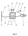
- FIG. 5 shows a use of a field device according to the invention Figure 1 to 4 ,
- the field device is a converter 50, which is connected to an electric motor 52 and controls or regulates this.
- the converter 50 is furthermore connected to a field bus 54, for example an AS-interface bus, more precisely a connecting line 55 connecting a slave 58 comprised by the converter 50 to the field bus 54 via a connection point 53.
- the slave 58 is thus integrated in the inverter 50; it is operated in transparent mode.
- a microprocessor which is designed as a controller 56 of the inverter 50, takes the forwarded by the slave data according to the arrangement in FIG. 3 and processes them using a state machine stored in it FIG.
- the controller 56 also serves the functionally typical for a drive or control of the motor 52, by controlling a power electronics connected to the latter 60.
- the microprocessor 11 off FIG. 3 So is advantageously integrated into the already necessary and therefore existing control 56 of the inverter 50.
- actuators 62 and sensors 64, 66 are connected directly or via a further bus 68, which are optionally integrated in the motor 52, as shown by way of example for sensor 66.
- the converter 50 is thus designed as a field device, as is advantageous for applications of the decentralized technique.
- 50 integrated in the converter, which allow use of the inverter 50 as a bus subscriber.
- the provision according to the invention of two logical slaves by a corresponding state machine in the controller 56 has the particularly advantageous effect of providing, on the one hand, binary data for the fieldbus 54 and the converter 50
- Control of actuators 62 or sensors 64, 66 are interchangeable and that on the other hand byte-oriented data, for example in the form of parameters for the inverter 50 or commands for operating the motor 52 or in the form of information about the state of inverter 50 or motor 52 can be transferred are.
- AS-interface bus instead of the AS-interface bus, another fieldbus, in particular CAN, CANopen, DeviceNet, Profibus, INTERBUS, Ethernet, real-time Ethernet, wireless LAN, EIB or LCN.
- AS-interface bus instead of the AS-interface bus, another fieldbus, in particular CAN, CANopen, DeviceNet, Profibus, INTERBUS, Ethernet, real-time Ethernet, wireless LAN, EIB or LCN.
Landscapes
- Engineering & Computer Science (AREA)
- Computer Networks & Wireless Communication (AREA)
- Signal Processing (AREA)
- Theoretical Computer Science (AREA)
- Quality & Reliability (AREA)
- Physics & Mathematics (AREA)
- General Engineering & Computer Science (AREA)
- General Physics & Mathematics (AREA)
- Information Transfer Systems (AREA)
- Small-Scale Networks (AREA)
- Radar Systems Or Details Thereof (AREA)
- Maintenance And Management Of Digital Transmission (AREA)
Claims (16)
- Procédé de transmission de données sécurisée,
dans lequel il est prévu un appareil conçu comme participant au bus,- l'appareil est muni, avant l'adressage, d'une adresse standard, en particulier de l'adresse « 0 », et est exploité dans un premier mode, en particulier un mode d'adressage standard, et réalise un esclave logique,- une autre adresse est affectée à l'appareil,
caractérisé en ce que
l'appareil réalise ensuite, après l'affectation d'adresse, au moins deux esclaves logiques, lesdits au moins deux esclaves logiques réalisés dans l'appareil après adressage étant utilisés pour la communication de données redondante relative à la sécurité et pour la transmission de données supplémentaires destinées à garantir des exigences relatives à la sécurité avec le bus,
le système de bus étant exploité avec au moins deux cycles
et des données utiles étant transmises dans un cycle et des données de contrôle dans le cycle précédent ou suivant,
les esclaves étant adressés, dans un mode d'adressage étendu, alternativement dans des cycles successifs avec l'adresse affectée sous la forme d'une adresse A, respectivement d'une adresse B. - Procédé selon la revendication 1,
caractérisé en ce que
lesdits au moins deux esclaves logiques réalisés dans l'esclave après adressage échangent des données de manière redondante avec un participant au bus via le bus. - Procédé selon la revendication 1 ou 2,
caractérisé en ce que
lesdits au moins deux esclaves logiques réalisés dans l'esclave après adressage échangent des données via un canal de communication respectif, les données étant échangées de manière redondante, en particulier les données présentant un contenu d'information identique dans chaque canal de communication. - Procédé selon une des revendications 1 à 3,
caractérisé en ce que
lesdits au moins deux esclaves logiques présentent des profils différents l'un de l'autre. - Procédé selon une des revendications 1 à 4,
caractérisé en ce que
au moins un desdits au moins deux esclaves logiques est un participant relatif à la sécurité. - Procédé selon une des revendications 1 à 5,
caractérisé en ce que
le taux d'erreurs par répétition, perte, insertion, permutation, altération et/ou retard de messages de bus est diminué par la transmission de données redondante. - Procédé selon une des revendications 1 à 6,
caractérisé en ce que
un système de bus est exploité avec au moins deux cycles,
et dans un premier cycle sont envoyées des informations qui sont répétées dans le deuxième cycle suivant. - Procédé selon une des revendications 1 à 7,
caractérisé en ce que
chaque participant au bus compare ses informations reçues dans le premier cycle avec les informations reçues dans le deuxième cycle. - Procédé selon une des revendications 1 à 8,
caractérisé en ce que
un système de bus est exploité avec au moins deux cycles,
et dans un cycle sont transmises des données utiles et dans le cycle précédent ou suivant des données de contrôle qui présentent au moins une des informations suivantes : un numéro courant des données utiles, une marque temporelle pour l'instant d'envoi des données utiles, une espérance de temps pour la durée de validité des données utiles, une confirmation de réception avec la répétition d'un message reçu auparavant, en particulier du maître, un identifiant de l'émetteur et/ou du destinataire. - Procédé selon une des revendications 1 à 9,
caractérisé en ce que
le participant au bus, un maître de bus et/ou un moniteur de sécurité exécute une routine d'erreur quand l'information comparée ne concorde pas et/ou qu'une erreur de transmission est détectée à l'aide des données de contrôle. - Procédé selon une des revendications 1 à 10,
caractérisé en ce que
la routine d'erreur comprend l'émission d'une instruction d'arrêt sécurisé à une unité d'entraînement
et/ou
la routine d'erreur comprend l'émission d'une notification d'erreur au maître. - Procédé selon une des revendications 1 à 11,
caractérisé en ce que
le bus est un bus de terrain, en particulier un des systèmes de bus CAN, CAN-Open, DeviceNet, Profibus, INTERBUS, AS-interface, Ethernet, Wireless-LAN, EIB, LCN, et/ou le participant au bus est exploité en tant qu'esclave AS-interface ou autre esclave de bus de terrain. - Appareil pour réaliser un procédé selon une des revendications 1 à 12,
caractérisé en ce que
sur l'appareil est réalisée une logique de commutation qui, lors d'un changement d'une adresse standard, en particulier d'une adresse de livraison ou de l'adresse « 0 », en une autre valeur d'adresse, fait passer l'appareil d'un premier dans un deuxième mode de fonctionnement,
l'appareil réalisant un esclave logique (3) dans le premier mode
et l'appareil réalisant deux esclaves logiques (3A, 3B) dans le deuxième mode. - Appareil selon la revendication 13,
caractérisé en ce que
l'appareil comprend un CI esclave et le processeur relié à celui-ci, en particulier un microprocesseur avec mémoire, le CI esclave étant utilisable en mode transparent,
le microprocesseur de l'appareil permettant la connexion à un bus étant en particulier intégré dans la commande du variateur de vitesse, en particulier dans la commande de l'électronique de puissance d'un variateur de vitesse. - Appareil selon une des revendications 13 ou 14,
caractérisé en ce que
le processeur est inclut dans un variateur de vitesse ou une commande, en particulier le processeur est prévu pour la commande et/ou la régulation d'actionneurs, de moteurs électriques ou analogues,
l'appareil étant en particulier un variateur de vitesse dans lequel est intégré un appareil permettant la connexion à un bus. - Appareil selon une des revendications 13 à 15,
caractérisé en ce que
des moyens de connexion pour la connexion d'actionneurs et/ou de capteurs et/ou d'un bus, par exemple d'un bus MOVILINK®, et/ou des sorties logiques sont inclus, ces moyens de connexion et/ou sorties logiques pouvant être commandés, respectivement lus, par le bus.
Applications Claiming Priority (2)
| Application Number | Priority Date | Filing Date | Title |
|---|---|---|---|
| DE102007043769.4A DE102007043769B4 (de) | 2007-09-13 | 2007-09-13 | Gerät, Verfahren zur Adressierung, Umrichter und Verfahren zur sicheren Datenübertragung |
| PCT/EP2008/007226 WO2009036891A1 (fr) | 2007-09-13 | 2008-09-04 | Procédé de transmission sécurisée de données et appareil approprié |
Publications (2)
| Publication Number | Publication Date |
|---|---|
| EP2203821A1 EP2203821A1 (fr) | 2010-07-07 |
| EP2203821B1 true EP2203821B1 (fr) | 2011-03-02 |
Family
ID=40219973
Family Applications (1)
| Application Number | Title | Priority Date | Filing Date |
|---|---|---|---|
| EP08801833A Active EP2203821B1 (fr) | 2007-09-13 | 2008-09-04 | Procédé de transmission sécurisée de données et appareil approprié |
Country Status (4)
| Country | Link |
|---|---|
| EP (1) | EP2203821B1 (fr) |
| AT (1) | ATE500549T1 (fr) |
| DE (2) | DE102007043769B4 (fr) |
| WO (1) | WO2009036891A1 (fr) |
Cited By (1)
| Publication number | Priority date | Publication date | Assignee | Title |
|---|---|---|---|---|
| CN104699055A (zh) * | 2015-02-13 | 2015-06-10 | 西安热工研究院有限公司 | 一种现场总线控制器及方法 |
Families Citing this family (7)
| Publication number | Priority date | Publication date | Assignee | Title |
|---|---|---|---|---|
| DE102010048286B4 (de) * | 2010-10-14 | 2013-08-01 | Kruno Pranjic | Untertagedatenübertragungsnetz mit Diagnosegerät |
| EP2731298A1 (fr) * | 2012-11-07 | 2014-05-14 | Siemens Aktiengesellschaft | Système de communication |
| DE102018201433A1 (de) * | 2018-01-31 | 2019-08-14 | Zf Friedrichshafen Ag | Übertragungssystem für Steuerdaten |
| DE102018001574B4 (de) * | 2018-02-28 | 2019-09-05 | WAGO Verwaltungsgesellschaft mit beschränkter Haftung | Master-Slave Bussystem und Verfahren zum Betrieb eines Bussystems |
| FR3097987A1 (fr) * | 2019-06-26 | 2021-01-01 | STMicroelectronics (Alps) SAS | Procede d’adressage d’un circuit integre sur un bus et dispositif correspondant |
| CN114467062B (zh) * | 2019-12-23 | 2024-09-10 | 深圳市英威腾电气股份有限公司 | 一种变频器的功能安全装置 |
| CN115098891B (zh) * | 2022-06-24 | 2026-02-27 | 浙江极氪智能科技有限公司 | 防止信号被篡改的程序运行方法、装置、设备及存储介质 |
Family Cites Families (10)
| Publication number | Priority date | Publication date | Assignee | Title |
|---|---|---|---|---|
| EP0685803B1 (fr) | 1994-06-03 | 2001-04-18 | Hyundai Electronics America | Procédé de fabrication d'un adaptateur de dispositif électrique |
| DE19742716C5 (de) * | 1997-09-26 | 2005-12-01 | Phoenix Contact Gmbh & Co. Kg | Steuer- und Datenübertragungsanlage und Verfahren zum Übertragen von sicherheitsbezogenen Daten |
| DE19743981C2 (de) | 1997-10-06 | 1999-11-25 | Ifm Electronic Gmbh | Verfahren zur Adressvergabe an einen Aktuator-Sensor-Interface-Slave sowie Aktuator-Sensor-Interface-Slave und Adressprogrammiergerät zur Durchführung des Verfahrens |
| DE19814102C2 (de) * | 1998-03-30 | 1999-05-12 | Siemens Ag | Datenübertragungsverfahren |
| DE20023852U1 (de) * | 2000-08-04 | 2006-12-14 | Ifm Electronic Gmbh | ASI-Slave |
| DE10038860B4 (de) * | 2000-08-04 | 2006-12-07 | Ifm Electronic Gmbh | Aktuator-Sensor-Interface-Slave |
| DE10206657B4 (de) | 2002-02-15 | 2006-06-08 | Schiff, Andreas, Dr. | Aktuator-Sensor-Interface für die Automation mit erweiterter Funktion |
| DE102005053103B4 (de) * | 2005-11-04 | 2008-04-24 | Phoenix Contact Gmbh & Co. Kg | Verfahren sowie System zur Übertragung von zyklischen und azyklischen Daten |
| DE102005055428B4 (de) * | 2005-11-21 | 2008-01-31 | Siemens Ag | Busmodul zum Anschluss an ein Bussystem sowie Verwendung eines solchen Busmoduls in einem AS-i-Bussystem |
| DE102006026972B3 (de) * | 2006-06-01 | 2007-10-25 | Sew-Eurodrive Gmbh & Co. Kg | Gerät und Verfahren zur Adressierung und Umrichter |
-
2007
- 2007-09-13 DE DE102007043769.4A patent/DE102007043769B4/de active Active
-
2008
- 2008-09-04 DE DE502008002772T patent/DE502008002772D1/de active Active
- 2008-09-04 WO PCT/EP2008/007226 patent/WO2009036891A1/fr not_active Ceased
- 2008-09-04 EP EP08801833A patent/EP2203821B1/fr active Active
- 2008-09-04 AT AT08801833T patent/ATE500549T1/de active
Cited By (1)
| Publication number | Priority date | Publication date | Assignee | Title |
|---|---|---|---|---|
| CN104699055A (zh) * | 2015-02-13 | 2015-06-10 | 西安热工研究院有限公司 | 一种现场总线控制器及方法 |
Also Published As
| Publication number | Publication date |
|---|---|
| WO2009036891A1 (fr) | 2009-03-26 |
| ATE500549T1 (de) | 2011-03-15 |
| DE102007043769A1 (de) | 2009-03-19 |
| DE102007043769B4 (de) | 2016-09-01 |
| DE502008002772D1 (de) | 2011-04-14 |
| EP2203821A1 (fr) | 2010-07-07 |
Similar Documents
| Publication | Publication Date | Title |
|---|---|---|
| EP2203821B1 (fr) | Procédé de transmission sécurisée de données et appareil approprié | |
| EP2030091B1 (fr) | Appareil et procédé d'adressage et convertisseurs | |
| DE102009042354C5 (de) | Verfahren und Vorrichtung zur sicherheitsgerichteten Kommunikation im Kommunikations-Netzwerk einer Automatisierungs-Anlage | |
| DE102014110017A1 (de) | Steuer- und Datenübertragungssystem, Gateway-Modul, E/A-Modul und Verfahren zur Prozesssteuerung | |
| EP2302472A2 (fr) | Système de contrôle de processus critiques pour la sécurité | |
| EP3177973B1 (fr) | Procédé de fonctionnement d'un automate de sécurité et réseau d'automatisation ayant un tel automate de sécurité | |
| EP2490372A1 (fr) | Réseau en temps réel planifié de manière topologique indépendant du port | |
| WO2018215299A1 (fr) | Traitement de données de processus | |
| EP2606610B1 (fr) | Procédé d'attribution d'adresses d'abonnés à un abonné au bus d'un système de commande à base de bus | |
| EP2484058B1 (fr) | Procédé d'adressage et réseau de communication utilisant un tel procédé d'adressage | |
| EP2233991A1 (fr) | Système d'automatisation orienté vers la sécurité doté d'une reproduction d'adresse automatique | |
| DE102007040424B4 (de) | Gerät zum Anschluss an einen Bus, Umrichter und Verfahren zur Adressierung | |
| EP2557464A1 (fr) | Procédé destiné au fonctionnement d'un système d'automatisation | |
| EP3948448B1 (fr) | Procédé de modification, bornier comprenant un logiciel, et système de borniers pour modification d'un logiciel de commande d'un système d'automatisation | |
| DE102007040425A1 (de) | Als Busteilnehmer vorgesehenes Gerät, Umrichter, Anlage und Verfahren | |
| WO2001031407A2 (fr) | Systeme et procede destines a empecher l'acces non autorise a un module, notamment dans des systemes automatises | |
| WO2005055538A1 (fr) | Procede de transmission de donnees via un bus de donnees, et systeme et passerelle permettant la mise en oeuvre dudit procede | |
| EP3632054B1 (fr) | Determination de noeuds d'un bus de données local | |
| EP3478541B1 (fr) | Dispositif de sécurité et procédé pour faire fonctionner un système | |
| DE102022000991A1 (de) | Automatisierungssystem und Verfahren zum Betrieb eines Automatisierungssystem | |
| EP3632051A1 (fr) | Initialisation d'abonnés de bus de données |
Legal Events
| Date | Code | Title | Description |
|---|---|---|---|
| PUAI | Public reference made under article 153(3) epc to a published international application that has entered the european phase |
Free format text: ORIGINAL CODE: 0009012 |
|
| 17P | Request for examination filed |
Effective date: 20100413 |
|
| AK | Designated contracting states |
Kind code of ref document: A1 Designated state(s): AT BE BG CH CY CZ DE DK EE ES FI FR GB GR HR HU IE IS IT LI LT LU LV MC MT NL NO PL PT RO SE SI SK TR |
|
| AX | Request for extension of the european patent |
Extension state: AL BA MK RS |
|
| GRAP | Despatch of communication of intention to grant a patent |
Free format text: ORIGINAL CODE: EPIDOSNIGR1 |
|
| DAX | Request for extension of the european patent (deleted) | ||
| GRAS | Grant fee paid |
Free format text: ORIGINAL CODE: EPIDOSNIGR3 |
|
| GRAA | (expected) grant |
Free format text: ORIGINAL CODE: 0009210 |
|
| AK | Designated contracting states |
Kind code of ref document: B1 Designated state(s): AT BE BG CH CY CZ DE DK EE ES FI FR GB GR HR HU IE IS IT LI LT LU LV MC MT NL NO PL PT RO SE SI SK TR |
|
| REG | Reference to a national code |
Ref country code: GB Ref legal event code: FG4D Free format text: NOT ENGLISH |
|
| REG | Reference to a national code |
Ref country code: CH Ref legal event code: EP |
|
| REG | Reference to a national code |
Ref country code: IE Ref legal event code: FG4D Free format text: LANGUAGE OF EP DOCUMENT: GERMAN |
|
| REF | Corresponds to: |
Ref document number: 502008002772 Country of ref document: DE Date of ref document: 20110414 Kind code of ref document: P |
|
| REG | Reference to a national code |
Ref country code: DE Ref legal event code: R096 Ref document number: 502008002772 Country of ref document: DE Effective date: 20110414 |
|
| REG | Reference to a national code |
Ref country code: NL Ref legal event code: VDEP Effective date: 20110302 |
|
| PG25 | Lapsed in a contracting state [announced via postgrant information from national office to epo] |
Ref country code: GR Free format text: LAPSE BECAUSE OF FAILURE TO SUBMIT A TRANSLATION OF THE DESCRIPTION OR TO PAY THE FEE WITHIN THE PRESCRIBED TIME-LIMIT Effective date: 20110603 Ref country code: LT Free format text: LAPSE BECAUSE OF FAILURE TO SUBMIT A TRANSLATION OF THE DESCRIPTION OR TO PAY THE FEE WITHIN THE PRESCRIBED TIME-LIMIT Effective date: 20110302 Ref country code: LV Free format text: LAPSE BECAUSE OF FAILURE TO SUBMIT A TRANSLATION OF THE DESCRIPTION OR TO PAY THE FEE WITHIN THE PRESCRIBED TIME-LIMIT Effective date: 20110302 Ref country code: NO Free format text: LAPSE BECAUSE OF FAILURE TO SUBMIT A TRANSLATION OF THE DESCRIPTION OR TO PAY THE FEE WITHIN THE PRESCRIBED TIME-LIMIT Effective date: 20110602 Ref country code: ES Free format text: LAPSE BECAUSE OF FAILURE TO SUBMIT A TRANSLATION OF THE DESCRIPTION OR TO PAY THE FEE WITHIN THE PRESCRIBED TIME-LIMIT Effective date: 20110613 Ref country code: SE Free format text: LAPSE BECAUSE OF FAILURE TO SUBMIT A TRANSLATION OF THE DESCRIPTION OR TO PAY THE FEE WITHIN THE PRESCRIBED TIME-LIMIT Effective date: 20110302 Ref country code: HR Free format text: LAPSE BECAUSE OF FAILURE TO SUBMIT A TRANSLATION OF THE DESCRIPTION OR TO PAY THE FEE WITHIN THE PRESCRIBED TIME-LIMIT Effective date: 20110302 |
|
| LTIE | Lt: invalidation of european patent or patent extension |
Effective date: 20110302 |
|
| PG25 | Lapsed in a contracting state [announced via postgrant information from national office to epo] |
Ref country code: BG Free format text: LAPSE BECAUSE OF FAILURE TO SUBMIT A TRANSLATION OF THE DESCRIPTION OR TO PAY THE FEE WITHIN THE PRESCRIBED TIME-LIMIT Effective date: 20110602 Ref country code: FI Free format text: LAPSE BECAUSE OF FAILURE TO SUBMIT A TRANSLATION OF THE DESCRIPTION OR TO PAY THE FEE WITHIN THE PRESCRIBED TIME-LIMIT Effective date: 20110302 Ref country code: CY Free format text: LAPSE BECAUSE OF FAILURE TO SUBMIT A TRANSLATION OF THE DESCRIPTION OR TO PAY THE FEE WITHIN THE PRESCRIBED TIME-LIMIT Effective date: 20110302 Ref country code: NL Free format text: LAPSE BECAUSE OF FAILURE TO SUBMIT A TRANSLATION OF THE DESCRIPTION OR TO PAY THE FEE WITHIN THE PRESCRIBED TIME-LIMIT Effective date: 20110302 Ref country code: SI Free format text: LAPSE BECAUSE OF FAILURE TO SUBMIT A TRANSLATION OF THE DESCRIPTION OR TO PAY THE FEE WITHIN THE PRESCRIBED TIME-LIMIT Effective date: 20110302 |
|
| REG | Reference to a national code |
Ref country code: IE Ref legal event code: FD4D |
|
| PG25 | Lapsed in a contracting state [announced via postgrant information from national office to epo] |
Ref country code: PT Free format text: LAPSE BECAUSE OF FAILURE TO SUBMIT A TRANSLATION OF THE DESCRIPTION OR TO PAY THE FEE WITHIN THE PRESCRIBED TIME-LIMIT Effective date: 20110704 Ref country code: EE Free format text: LAPSE BECAUSE OF FAILURE TO SUBMIT A TRANSLATION OF THE DESCRIPTION OR TO PAY THE FEE WITHIN THE PRESCRIBED TIME-LIMIT Effective date: 20110302 Ref country code: IE Free format text: LAPSE BECAUSE OF FAILURE TO SUBMIT A TRANSLATION OF THE DESCRIPTION OR TO PAY THE FEE WITHIN THE PRESCRIBED TIME-LIMIT Effective date: 20110302 |
|
| PG25 | Lapsed in a contracting state [announced via postgrant information from national office to epo] |
Ref country code: CZ Free format text: LAPSE BECAUSE OF FAILURE TO SUBMIT A TRANSLATION OF THE DESCRIPTION OR TO PAY THE FEE WITHIN THE PRESCRIBED TIME-LIMIT Effective date: 20110302 Ref country code: RO Free format text: LAPSE BECAUSE OF FAILURE TO SUBMIT A TRANSLATION OF THE DESCRIPTION OR TO PAY THE FEE WITHIN THE PRESCRIBED TIME-LIMIT Effective date: 20110302 Ref country code: IS Free format text: LAPSE BECAUSE OF FAILURE TO SUBMIT A TRANSLATION OF THE DESCRIPTION OR TO PAY THE FEE WITHIN THE PRESCRIBED TIME-LIMIT Effective date: 20110702 Ref country code: SK Free format text: LAPSE BECAUSE OF FAILURE TO SUBMIT A TRANSLATION OF THE DESCRIPTION OR TO PAY THE FEE WITHIN THE PRESCRIBED TIME-LIMIT Effective date: 20110302 |
|
| PLBE | No opposition filed within time limit |
Free format text: ORIGINAL CODE: 0009261 |
|
| STAA | Information on the status of an ep patent application or granted ep patent |
Free format text: STATUS: NO OPPOSITION FILED WITHIN TIME LIMIT |
|
| 26N | No opposition filed |
Effective date: 20111205 |
|
| PG25 | Lapsed in a contracting state [announced via postgrant information from national office to epo] |
Ref country code: DK Free format text: LAPSE BECAUSE OF FAILURE TO SUBMIT A TRANSLATION OF THE DESCRIPTION OR TO PAY THE FEE WITHIN THE PRESCRIBED TIME-LIMIT Effective date: 20110302 Ref country code: PL Free format text: LAPSE BECAUSE OF FAILURE TO SUBMIT A TRANSLATION OF THE DESCRIPTION OR TO PAY THE FEE WITHIN THE PRESCRIBED TIME-LIMIT Effective date: 20110302 |
|
| REG | Reference to a national code |
Ref country code: DE Ref legal event code: R097 Ref document number: 502008002772 Country of ref document: DE Effective date: 20111205 |
|
| BERE | Be: lapsed |
Owner name: SEW-EURODRIVE G.M.B.H. & CO. KG Effective date: 20110930 |
|
| PG25 | Lapsed in a contracting state [announced via postgrant information from national office to epo] |
Ref country code: MC Free format text: LAPSE BECAUSE OF NON-PAYMENT OF DUE FEES Effective date: 20110930 |
|
| PG25 | Lapsed in a contracting state [announced via postgrant information from national office to epo] |
Ref country code: IT Free format text: LAPSE BECAUSE OF FAILURE TO SUBMIT A TRANSLATION OF THE DESCRIPTION OR TO PAY THE FEE WITHIN THE PRESCRIBED TIME-LIMIT Effective date: 20110302 |
|
| PG25 | Lapsed in a contracting state [announced via postgrant information from national office to epo] |
Ref country code: BE Free format text: LAPSE BECAUSE OF NON-PAYMENT OF DUE FEES Effective date: 20110930 |
|
| PG25 | Lapsed in a contracting state [announced via postgrant information from national office to epo] |
Ref country code: MT Free format text: LAPSE BECAUSE OF FAILURE TO SUBMIT A TRANSLATION OF THE DESCRIPTION OR TO PAY THE FEE WITHIN THE PRESCRIBED TIME-LIMIT Effective date: 20110302 |
|
| REG | Reference to a national code |
Ref country code: CH Ref legal event code: PL |
|
| PG25 | Lapsed in a contracting state [announced via postgrant information from national office to epo] |
Ref country code: LU Free format text: LAPSE BECAUSE OF NON-PAYMENT OF DUE FEES Effective date: 20110904 |
|
| PG25 | Lapsed in a contracting state [announced via postgrant information from national office to epo] |
Ref country code: LI Free format text: LAPSE BECAUSE OF NON-PAYMENT OF DUE FEES Effective date: 20120930 Ref country code: CH Free format text: LAPSE BECAUSE OF NON-PAYMENT OF DUE FEES Effective date: 20120930 |
|
| PG25 | Lapsed in a contracting state [announced via postgrant information from national office to epo] |
Ref country code: TR Free format text: LAPSE BECAUSE OF FAILURE TO SUBMIT A TRANSLATION OF THE DESCRIPTION OR TO PAY THE FEE WITHIN THE PRESCRIBED TIME-LIMIT Effective date: 20110302 |
|
| PG25 | Lapsed in a contracting state [announced via postgrant information from national office to epo] |
Ref country code: HU Free format text: LAPSE BECAUSE OF FAILURE TO SUBMIT A TRANSLATION OF THE DESCRIPTION OR TO PAY THE FEE WITHIN THE PRESCRIBED TIME-LIMIT Effective date: 20110302 |
|
| REG | Reference to a national code |
Ref country code: AT Ref legal event code: MM01 Ref document number: 500549 Country of ref document: AT Kind code of ref document: T Effective date: 20130904 |
|
| PG25 | Lapsed in a contracting state [announced via postgrant information from national office to epo] |
Ref country code: AT Free format text: LAPSE BECAUSE OF NON-PAYMENT OF DUE FEES Effective date: 20130904 |
|
| REG | Reference to a national code |
Ref country code: FR Ref legal event code: PLFP Year of fee payment: 9 |
|
| REG | Reference to a national code |
Ref country code: FR Ref legal event code: PLFP Year of fee payment: 10 |
|
| REG | Reference to a national code |
Ref country code: FR Ref legal event code: PLFP Year of fee payment: 11 |
|
| PGFP | Annual fee paid to national office [announced via postgrant information from national office to epo] |
Ref country code: DE Payment date: 20250930 Year of fee payment: 18 |
|
| PGFP | Annual fee paid to national office [announced via postgrant information from national office to epo] |
Ref country code: GB Payment date: 20250731 Year of fee payment: 18 |
|
| PGFP | Annual fee paid to national office [announced via postgrant information from national office to epo] |
Ref country code: FR Payment date: 20250808 Year of fee payment: 18 |
|
| REG | Reference to a national code |
Ref country code: DE Ref legal event code: R084 Ref document number: 502008002772 Country of ref document: DE |