EP2204244A1 - Procédé de fabrication d'une vis autotaraudeuse - Google Patents
Procédé de fabrication d'une vis autotaraudeuse Download PDFInfo
- Publication number
- EP2204244A1 EP2204244A1 EP09177139A EP09177139A EP2204244A1 EP 2204244 A1 EP2204244 A1 EP 2204244A1 EP 09177139 A EP09177139 A EP 09177139A EP 09177139 A EP09177139 A EP 09177139A EP 2204244 A1 EP2204244 A1 EP 2204244A1
- Authority
- EP
- European Patent Office
- Prior art keywords
- thread
- recesses
- embossing
- welding
- screw
- Prior art date
- Legal status (The legal status is an assumption and is not a legal conclusion. Google has not performed a legal analysis and makes no representation as to the accuracy of the status listed.)
- Granted
Links
Images


Classifications
-
- B—PERFORMING OPERATIONS; TRANSPORTING
- B21—MECHANICAL METAL-WORKING WITHOUT ESSENTIALLY REMOVING MATERIAL; PUNCHING METAL
- B21K—MAKING FORGED OR PRESSED METAL PRODUCTS, e.g. HORSE-SHOES, RIVETS, BOLTS OR WHEELS
- B21K1/00—Making machine elements
- B21K1/56—Making machine elements screw-threaded elements
-
- F—MECHANICAL ENGINEERING; LIGHTING; HEATING; WEAPONS; BLASTING
- F16—ENGINEERING ELEMENTS AND UNITS; GENERAL MEASURES FOR PRODUCING AND MAINTAINING EFFECTIVE FUNCTIONING OF MACHINES OR INSTALLATIONS; THERMAL INSULATION IN GENERAL
- F16B—DEVICES FOR FASTENING OR SECURING CONSTRUCTIONAL ELEMENTS OR MACHINE PARTS TOGETHER, e.g. NAILS, BOLTS, CIRCLIPS, CLAMPS, CLIPS OR WEDGES; JOINTS OR JOINTING
- F16B25/00—Screws that cut thread in the body into which they are screwed, e.g. wood screws
- F16B25/001—Screws that cut thread in the body into which they are screwed, e.g. wood screws characterised by the material of the body into which the screw is screwed
- F16B25/0026—Screws that cut thread in the body into which they are screwed, e.g. wood screws characterised by the material of the body into which the screw is screwed the material being a hard non-organic material, e.g. stone, concrete or drywall
-
- F—MECHANICAL ENGINEERING; LIGHTING; HEATING; WEAPONS; BLASTING
- F16—ENGINEERING ELEMENTS AND UNITS; GENERAL MEASURES FOR PRODUCING AND MAINTAINING EFFECTIVE FUNCTIONING OF MACHINES OR INSTALLATIONS; THERMAL INSULATION IN GENERAL
- F16B—DEVICES FOR FASTENING OR SECURING CONSTRUCTIONAL ELEMENTS OR MACHINE PARTS TOGETHER, e.g. NAILS, BOLTS, CIRCLIPS, CLAMPS, CLIPS OR WEDGES; JOINTS OR JOINTING
- F16B25/00—Screws that cut thread in the body into which they are screwed, e.g. wood screws
- F16B25/0036—Screws that cut thread in the body into which they are screwed, e.g. wood screws characterised by geometric details of the screw
- F16B25/0042—Screws that cut thread in the body into which they are screwed, e.g. wood screws characterised by geometric details of the screw characterised by the geometry of the thread, the thread being a ridge wrapped around the shaft of the screw
- F16B25/0052—Screws that cut thread in the body into which they are screwed, e.g. wood screws characterised by geometric details of the screw characterised by the geometry of the thread, the thread being a ridge wrapped around the shaft of the screw the ridge having indentations, notches or the like in order to improve the cutting behaviour
-
- F—MECHANICAL ENGINEERING; LIGHTING; HEATING; WEAPONS; BLASTING
- F16—ENGINEERING ELEMENTS AND UNITS; GENERAL MEASURES FOR PRODUCING AND MAINTAINING EFFECTIVE FUNCTIONING OF MACHINES OR INSTALLATIONS; THERMAL INSULATION IN GENERAL
- F16B—DEVICES FOR FASTENING OR SECURING CONSTRUCTIONAL ELEMENTS OR MACHINE PARTS TOGETHER, e.g. NAILS, BOLTS, CIRCLIPS, CLAMPS, CLIPS OR WEDGES; JOINTS OR JOINTING
- F16B25/00—Screws that cut thread in the body into which they are screwed, e.g. wood screws
- F16B25/0036—Screws that cut thread in the body into which they are screwed, e.g. wood screws characterised by geometric details of the screw
- F16B25/0042—Screws that cut thread in the body into which they are screwed, e.g. wood screws characterised by geometric details of the screw characterised by the geometry of the thread, the thread being a ridge wrapped around the shaft of the screw
- F16B25/0068—Screws that cut thread in the body into which they are screwed, e.g. wood screws characterised by geometric details of the screw characterised by the geometry of the thread, the thread being a ridge wrapped around the shaft of the screw with multiple-threads, e.g. a double thread screws
Definitions
- the invention relates to a method for producing a thread-forming screw, the type mentioned in claim 1, and an embossing device for carrying out the method.
- Thread-forming screws have a shank, which is at least partially provided with a thread as an external thread and having, for example, at one end a screw head as load application means. So that thread-forming or thread-cutting screws can furrow a mating thread into the substrate, the thread is hardened to increase the strength, for example, in some areas.
- screws such as concrete screws, are made of corrosion-resistant steel materials, which normally can not be increased in strength by a heat treatment to the extent that a secure indenting into the concrete is possible.
- a thread-forming screw made of a metal are welded to the cutting body of a metal with a higher carbon content.
- the cutting bodies thus have a hardness which is greater than the hardness of the screw or the thread.
- the cutting body have in the welded state on a small projection to the outer contour of the thread.
- a disadvantage of the known solution is that when welding the cutting body of the base material at least the thread or the screw must be sufficiently softened in this area, so that the cutting body can be pressed into the thread. Only in this way can according to the EP 1 595 080 B1 the cutting body anchored sufficiently in the thread or in the core and an excessive projection on the outer contour of the thread can be prevented. Due to the process time required for this purpose, the screw material is locally strongly heated, resulting in a structural change of the base material leads and can lead to cracking in the material. In the fixing area, the corrosion resistance of the shaft may decrease in some areas due to the effect of heat.
- the object of the invention is to provide a method for producing a thread-forming screw, in particular made of a corrosion-resistant material, with welded-in cutting bodies, which avoids the aforementioned disadvantages and allows easy production of the screw.
- the thread on the shaft z. B. formed in a rolling process.
- a plurality of recesses or depressions are embossed into the thread, wherein the material of the screw is at least partially solidified in this area.
- several compact cutting body are welded into the previously created recesses in the thread, wherein the cutting body are made of a hard material and have a hardness greater than the hardness of the thread.
- the cutting bodies have an extent extending in the direction of the thread, which corresponds to the extent of the corresponding recesses in the thread.
- the arrangement of the cutting body in recesses in the thread is a lower melting of the base material of the thread or the screw, whereby a corrosion resistance of the screw is largely retained even in the fixed portion of the cutting body.
- the recess for receiving a cutting body has, for example, an extension in the direction of the thread path, which essentially corresponds to the corresponding extent of the cutting body in the arranged state thereof in the thread.
- the recesses are introduced during embossing in only one forming step in the thread, the created recess or depression can extend into the core of the screw.
- the recesses are formed, for example, point or line.
- Under punctiform is understood in this context a recess, whose longitudinal extension along the thread corresponds at most to 1.5 times the width of the thread at the thread root, ie at the outside of the shaft.
- line-shaped means a recess which has a longitudinal extent along the thread of more than 1.5 times the width of the thread at the thread root, ie on the outside of the shaft.
- the compact cutting body are so integrally connected by the welding in the recesses with the thread that they are held in as well as counter to the screwing of the thread-forming screw and radially enough to the screw.
- the wear of the thread of the screw formed integrally with the shank is also lowered on hard mineral substrates such as high-strength concrete types compared to a thread-forming screw without a cutting body, whereby the thread-forming process is improved during setting of the thread-forming screw.
- the corrosion resistance of the screw is largely retained, whereby the low wear of the thread higher load values compared to existing systems are achieved with a set screw.
- no additional processing of the core is required, which is z. B. also has an advantageous effect on the corrosion resistance and on an economical production of the thread-forming screw.
- the screw is advantageously made of an austenitic stainless steel.
- the cutting bodies already have a cutting geometry corresponding to their function and fulfill this function directly after fixing in the thread.
- An elaborate, mechanical reworking of the welded in the thread cutting body by, for example, grinding, milling or hardening is not required.
- the surface hardness of the cutting body and thus the advantageous thread-forming properties of the cutting body are retained.
- the shape of the cutting body and its number are arbitrary and are advantageously turned off on the effect to be achieved.
- the cutting bodies have a ball-like, cylindrical, cuboid, conical or pyramidal configuration.
- the cutting body can also be designed as a so-called cutting tooth, as it is known from demolition and mining technology.
- the cutting bodies can also be arranged inclined to a tangent applied to the outer contour of the thread. The inclination angle is for example 5 ° to 15 °.
- the number of cutting bodies arranged in the thread is dependent on the length of the thread and the furrowing and the base material, in which the thread-forming screw is to be set. In an advantageous embodiment of the inventive thread-forming screw a certain number z are only in a range starting from the setting direction end. B. from four to fifteen cutting bodies spaced from each other provided in the thread, wherein the rest of the thread has no cutting body. In order to achieve specific set properties, differently shaped cutting bodies can also be arranged on a thread-forming screw.
- the fixed cutting body continue the thread at least partially harmonious, resulting in advantageous Furcheigenschaften the screw and a low wear of the thread is achieved.
- the defined cutting bodies protrude at least in regions radially outward over the thread, whereby a strong furrowing and thus an increased degradation of the grooved substrate is produced.
- cutting bodies made of a weld material can also be arranged on the thread, which are manufactured, for example, in a metal arc gas welding process or by means of laser clipping.
- These additional cutting means are advantageously arranged according to requirements also in previously embossed recesses on the thread.
- the additional cutting means support the welded in the recesses, compact cutting body made of a hard material when furling the counter-thread in the ground.
- the cutting body made of a weld material are provided alternately to the compact cutting bodies of hard material on the thread.
- compact cutting bodies made of hard material are arranged in recesses and subsequently cutting bodies of welding material are cut into recesses or directly on the thread.
- cutting body of welding material and subsequently compact cutting body made of hard material in the thread can in a further alternative in the field of Thread that comes into contact with the ground first, cutting body of welding material and subsequently compact cutting body made of hard material in the thread to be arranged.
- the embossing of the recesses and the welding of the compact cutting body are directly interlinked with each other, so that the screw for welding the cutting body into the recesses need not be re-aligned.
- the screw is held during embossing of the recesses by a manipulator, then moved by this in the welding station and held during the welding process of this.
- a plurality of successive recesses are embossed at a distance from each other, which increases starting from a free end portion of the shaft along the course of the thread.
- the cutting bodies are advantageously arranged close to each other. In a section facing away from the setting direction end, the cutting body can be further spaced from each other, since these cutting body essentially have only a nachfurchende effect and only serve an advantageous setting process of the screw in the ground.
- the recesses each have a bottom portion after embossing, which is spaced radially to the outer periphery of the shaft.
- the bottom portion of the recess is advantageously spaced apart from the outer circumference of the shaft such that only the material of the thread formed on the shaft is melted during welding of the cutting body in the recess and thus the shaft is exposed to a heat stress at most slightly.
- the corrosion resistance of the shaft of a screw made of a corrosion-resistant material is largely retained.
- the recesses preferably have walls after embossing, and the cutting body coming to lie in the recesses is arranged spaced apart at least from one of the walls. This provides defined clearances for removed material, which leads to an improved thread rolling process and thus to a facilitated setting behavior of the screw according to the invention.
- the cutting body is determined by welding technology only at the bottom portion of the recess and arranged spaced on both side walls of the recess. This freestanding arrangement of the cutting means in the recess z. B. in combination with an ovaloid or spherical configuration of the cutting body leads to an advantageous Einschneid or Gewindefurchlui and thus to an improved setting behavior.
- the setting time for a screw lowers and, on the other hand, a lower torque than the conventional thread-forming screws for setting the screw must be applied, which significantly contributes to the economy of the screw produced by the method according to the invention.
- the cutting body is arranged directly adjacent to one of the walls of the recess and spaced from the other, this opposite wall, whereby a front, behind or laterally next to the cutting body defined clearance for material removed is provided.
- the compact cutting body are determined by means of electrical resistance welding in the recesses, which ensures a sufficient cohesive fixing of the cutting body in the recesses.
- electrical resistance welding a high current is caused to flow between two bodies and at the same time the two bodies are pressed together under pressure. In the place of the greatest electrical resistance, usually at the transition between the two bodies, a great heat is created, which melts adjacent base material, whereby a connection between the bodies is created.
- different types of resistance welding process such. B. the Spitzenenzündungsvon be used.
- methods should be selected which generate small heat-affected zones in the base material, in particular of the shaft, and identify short cycle times.
- the thread-forming screw is not only easy to manufacture, but the arrangement of the cutting body has only a small influence on the corrosion resistance of the screw.
- Alternative welding methods for determining the compact cutting bodies in the recesses are friction welding, orbital welding, laser welding or ultrasonic welding.
- the welding process for fixing the cutting body in the recesses takes place in several phases, so that the compact cutting body can be fixed to the thread with specially optimized for this application welding programs.
- the welding programs regulate the time sequences and the strength of the applied welding currents.
- the phases of the welding process are controlled by a closed loop, the result of feedback affects the manipulated variables of the welding device. Any occurring disturbances and changes are taken into account and corrected in the control.
- small heat-affected zones are formed, which minimizes the degree of melting of the core and / or thread material, which is particularly important for corrosion resistance.
- the areawise mixing between the base material and the cutting body should be as small as possible, but sufficiently large, so that the cutting body is held securely in the thread and the force acting on him during the setting of the screw forces in the thread and thus in the shaft are derived.
- the welding process comprises a first phase for heating the base material of the screw, a second phase for fixing the cutting bodies in the recesses and a third phase for cooling the produced weld.
- the first phase is the controlled warm-up phase in which localized softening of the joining partners, in this case the screw material and the compact cutting bodies, ensure secure contacting and in some cases a preheating of the joining partners.
- the second phase is the controlled welding phase.
- the third phase is the controlled cooling phase, which is particularly advantageous for hard cutting bodies, as it minimizes the formation of cracks due to thermal shock during cooling.
- the slope of delta power to delta time in the second phase is greater than in the first phase, whereby a sufficient determination of the cutting body is ensured in the recesses in an advantageous manner.
- the welding process preferably takes place with a defined contact force of 5 N to 100 N, which acts on the welding body from a holder for the welding body.
- the value of the defined contact pressure is 10 N to 60 N and in particular 15 N to 40 N.
- the defined contact force acts multiaxial, wherein the contact pressure can advantageously act two- or three-axis. Due to the corresponding multi-axis mobility of the holder for the welding body, resistance welding z. As a welding electrode, the compact cutting body, especially during the second and possibly during the third phase, a relative movement to the shaft and thread of the screw experienced, whereby the Anbinde redesign the created determination in the recess is further improved.
- a two-axis acting, defined contact force acts on the cutting body on the one hand radially, d. H. in the direction of the shaft, with 5 N to 100 N and on the other tangent, d. H. in the direction of the thread, with 5 N to 100 N.
- the value of the contact pressure components of the defined contact force in the radial and tangential direction does not necessarily have to be identical.
- An embossing device for embossing recesses in a thread of a screw has at least one holder for holding the screw during the embossing process and at least one embossing punch for creating the recess in the thread of the screw.
- the shaping portion of the at least one embossing punch is formed according to the desired configuration of the recess to be created.
- the at least one support holds the screw in the appropriate orientation so that the recess at the desired position in the thread can be made in a repeatable and precise manner.
- a plurality of dies are provided for the simultaneous creation of a plurality of recesses, whereby the cycle times for producing the thread-forming screw against a single formation of each recess can be reduced.
- an embossing die can simultaneously form more than one recess in the thread.
- a plurality of dies are provided, which each form one or more recesses in a Zustallvorgang in the thread of the screw.
- embossing stamps are provided or if an embossing stamp has several shaping sections, these are advantageously shaped identically.
- the at least one holder and the at least one embossing die are individually controlled, whereby the holding forces acting on the screw as well as the embossing forces are differently adjustable.
- the holding forces acting on the screw as well as the embossing forces are differently adjustable.
- thread-forming screw 11 comprises a shaft 12 made of a corrosion-resistant material, for example a steel material having a carbon content below 0.5%, and an integrally formed on the shaft 12 thread 13, the region of a free end portion 14, starting in the direction of a second end 15 of the shaft 12 extends.
- a hexagonal head 16 is provided at the second end 15 of the shaft 12.
- a plurality of elongated recesses 21 are provided for receiving compact cutting bodies 22 made of a hard metal in the form of balls whose hardness is greater than the hardness of the thread.
- the recesses 21 have lateral walls 23 and a bottom portion 24, which is radially spaced from the outer circumference of the shaft 12.
- the cutting body 22 are spaced from the walls 23 of the recesses 21 and extend beyond the thread radially in some areas to the outside.
- the cutting body 22 are welded to create a cohesive connection by means of electrical resistance welding in the thread.
- the recesses 21 and thus the recesses 21 and thus the cutting body 22 have along the course of the thread spacings A1, A2, etc., which increase from the free end portion 14 of the shaft 12 in the direction of the second end 15 of the shaft 12 ,
- thread-forming screw 31 also has a shaft 32 made of a corrosion-resistant metal, on which a thread 33 is formed, which extends in regions from a free end portion 34, starting in the direction of a second end of the shaft 32.
- a plurality of recesses 41 for receiving compact cutting bodies 42 are provided from a hard material in the form of truncated pyramids.
- the recesses 41 have an extension in the direction of the thread path, which corresponds to the corresponding extension of the cutting body 42 arranged in the thread 33.
- the cutting bodies 42 adjacent to the outlet of the thread continue the thread 33 in a harmonious manner and, in a region facing the second end of the shank, have in certain regions a radial projection to the outside relative to the thread 33.
- the cutting bodies 42 are welded in the thread.
- the recesses 41 and thus the cutting bodies 42 may also have, along the course of the thread, distances which increase from the free end region 34 of the shaft 32 towards a second end of the shaft 32.
- a partially circumferentially arranged thread 53 is formed on the shaft 52 of the screw 51.
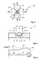
- the screw 51 of the embossing device 101 for Embossing recesses 56 in the threaded 53 supplied.
- the screw 51 is held in position by three brackets 102 offset by 90 ° from each other.
- an embossing die 103 which has a shaping portion 104 at its end facing the holders 102, moves relative to the shank 52 of the screw 51, wherein the elongate recess 56, for example, is formed in the thread 53.
- the brackets 102 and the die 103 are individually controlled.
- the recess 56 has lateral walls 58 and a, to the outer circumference of the shaft 52 spaced bottom portion 59.
- the embossing device can also have more embossing dies and fewer holders, so that a plurality of recesses in the thread of the screw are simultaneously produced during the relative displacement of these embossing dies towards the screw.
- the embossing stamp may also have more than one shaping section, so that a plurality of recesses are simultaneously produced in the thread of the screw when this embossing stamp is displaced relative to the screw.
- the screw 51 is fed to a welding station, not shown here, in which the compact cutting body 57 is fixed by means of an electrical resistance welding in the recess 56 on the thread 53 ( Fig. 5 ).
- the cutting body 57 is held during the welding process by a holder 121, here a welding electrode, with a defined contact force of 15 N to 40 N acting on the welding body 57 coming from the holder 121 on the welding body 57.
- This contact pressure acts advantageously multi-axially, for example biaxially, on the one hand radially in the direction of the shaft 52 and on the other hand tangentially in the direction of the thread 53rd
- the compact cutting body 57 is arranged on both sides spaced from the walls 58 for the creation of clearances 54 for mined material.
- the embossing of the recesses 56 and the welding of the compact cutting body 57 are directly linked, so that the screw 51 does not have to be aligned again after the embossing process for the downstream welding process.
- the welding process for fixing the cutting body 57 in the recesses 56 takes place in three phases.
- the time in ms is plotted on the abscissa axis and the power supplied in kW on the ordinate axis.
- the power is successively increased over a certain period of time, wherein the base material of the screw 51 and the Cutting body 57 are warmed up.
- the portion 116 of the first phase 111 runs on a positive slope.
- the first phase 111 may consist of several sub-phases, wherein the course of the resulting section is not such. In Fig. 6 shown must necessarily be linear.
- the cutting bodies 57 are set in the recesses 56, with more power being supplied over a shorter period of time in this phase 112 compared with the first phase 111.
- the profile of section 117 has a greater positive slope of delta power to delta time than section 116 in first phase 111.
- the second phase 112 may also consist of several sub-phases, the course of the resulting section not such. In Fig. 6 shown must necessarily be linear.
- the power over a certain time is withdrawn until the power of the power at the beginning of the welding process or the power at the beginning of the first phase 111 corresponds.
- a cooling of the created weld takes place.
- the portion 118 of the third phase 113 has a negative slope.
- the third phase 113 may also consist of several sub-phases, the course of the resulting section not such. In Fig. 6 shown must necessarily be linear.
- the heat generated during the welding operation is limited to a fixing region 60 which advantageously does not extend or extends only slightly into the shaft 52.
- FIG. 7 shows a further arrangement of a cutting body 67 in an elongated recess 66 in the thread 63 of a screw 61, wherein the cutting body 67 is arranged only to a wall 68 of the recess 66 spaced.
- this type of arrangement of the cutting body 67 is in the recess 66 a one-sided and compared to the in FIG. 5 shown arrangement of the cutter body 57 larger clearance 64 created.
- FIG. 8 a circular-cylindrical cutting body 77 of a thread-forming screw 71, which is arranged in a recess 76 in the thread 73 at an angle C to a bottom portion 79 and spaced from a wall 78.
Landscapes
- Engineering & Computer Science (AREA)
- General Engineering & Computer Science (AREA)
- Mechanical Engineering (AREA)
- Physics & Mathematics (AREA)
- Geometry (AREA)
- Forging (AREA)
- Connection Of Plates (AREA)
- Transmission Devices (AREA)
Applications Claiming Priority (1)
| Application Number | Priority Date | Filing Date | Title |
|---|---|---|---|
| DE102008054824A DE102008054824A1 (de) | 2008-12-17 | 2008-12-17 | Verfahren zur Herstellung einer gewindefurchenden Schraube |
Publications (2)
| Publication Number | Publication Date |
|---|---|
| EP2204244A1 true EP2204244A1 (fr) | 2010-07-07 |
| EP2204244B1 EP2204244B1 (fr) | 2012-09-12 |
Family
ID=41698181
Family Applications (1)
| Application Number | Title | Priority Date | Filing Date |
|---|---|---|---|
| EP09177139A Active EP2204244B1 (fr) | 2008-12-17 | 2009-11-26 | Procédé de fabrication d'une vis autotaraudeuse |
Country Status (7)
| Country | Link |
|---|---|
| US (1) | US8696477B2 (fr) |
| EP (1) | EP2204244B1 (fr) |
| CN (1) | CN101745599B (fr) |
| CA (1) | CA2688781C (fr) |
| DE (1) | DE102008054824A1 (fr) |
| ES (1) | ES2391805T3 (fr) |
| TW (1) | TWI520797B (fr) |
Cited By (7)
| Publication number | Priority date | Publication date | Assignee | Title |
|---|---|---|---|---|
| EP2511541A3 (fr) * | 2011-04-14 | 2013-10-02 | TOGE-Dübel A. Gerhard KG | Vis-taraud |
| DE102012216117A1 (de) | 2012-09-12 | 2014-03-13 | Hilti Aktiengesellschaft | Verfahren zum Herstellen einer selbstschneidenden Schraube |
| EP3421623A1 (fr) | 2017-06-26 | 2019-01-02 | HILTI Aktiengesellschaft | Acier durcissable par formation de martensite et son utilisation, en particulier destiné à fabriquer une vis |
| EP3438475A1 (fr) * | 2017-07-31 | 2019-02-06 | fischerwerke GmbH & Co. KG | Vis à béton |
| EP3536812A1 (fr) | 2018-03-08 | 2019-09-11 | HILTI Aktiengesellschaft | Vis composée de deux métaux à acier marténsitique thermodurcissable |
| EP3620673A1 (fr) | 2018-09-10 | 2020-03-11 | fischerwerke GmbH & Co. KG | Vis à béton |
| EP3620672A1 (fr) | 2018-09-10 | 2020-03-11 | fischerwerke GmbH & Co. KG | Vis à béton |
Families Citing this family (11)
| Publication number | Priority date | Publication date | Assignee | Title |
|---|---|---|---|---|
| DE102010043837A1 (de) * | 2010-11-12 | 2012-05-16 | Hilti Aktiengesellschaft | Schlagwerkskörper, Schlagwerk und Handwerkzeugmaschine mit einem Schlagwerk |
| DE102010055210A1 (de) * | 2010-12-20 | 2012-06-21 | Ejot Gmbh & Co. Kg | Schraube aus niedrig legiertem Kohlenstoffstahl und Verfahren zur Herstellung einer derartigen Schraube |
| CN105452685B (zh) * | 2013-10-03 | 2017-06-27 | 株式会社青山制作所 | 螺栓 |
| US9683592B2 (en) * | 2015-07-13 | 2017-06-20 | Masterpiece Hardware Industrial Co. Ltd. | Wooden screw |
| EP3130811A1 (fr) | 2015-08-12 | 2017-02-15 | HILTI Aktiengesellschaft | Procede de pose d'une vis |
| CN106975725B (zh) * | 2017-04-30 | 2018-02-27 | 盈锋志诚嘉精密五金(深圳)有限公司 | 打头搓牙一体化的螺丝生产设备及其螺丝生产方法 |
| JP7155256B2 (ja) * | 2017-10-09 | 2022-10-18 | コンメッド コーポレーション | 容易に開始できるカニューレ状骨スクリュー |
| US20190154072A1 (en) * | 2017-11-17 | 2019-05-23 | Black & Decker Inc. | Screw anchors and manufacturing methods |
| EP3760885A1 (fr) * | 2019-07-03 | 2021-01-06 | Hilti Aktiengesellschaft | Vis pour béton à enfoncer au marteau |
| EP3869051A1 (fr) | 2020-02-18 | 2021-08-25 | Hilti Aktiengesellschaft | Vis inoxydable bimétallique |
| EP4184021A1 (fr) | 2021-11-18 | 2023-05-24 | Hilti Aktiengesellschaft | Vis à trois composants |
Citations (2)
| Publication number | Priority date | Publication date | Assignee | Title |
|---|---|---|---|---|
| EP1655498A1 (fr) * | 2004-11-08 | 2006-05-10 | HILTI Aktiengesellschaft | Vis autotaraudeuse et procédé pour sa fabrication |
| EP1595080B1 (fr) | 2003-02-18 | 2006-11-08 | TOGE-Dübel A. Gerhard KG | Vis taraudeuse |
Family Cites Families (4)
| Publication number | Priority date | Publication date | Assignee | Title |
|---|---|---|---|---|
| US4420848A (en) * | 1982-04-15 | 1983-12-20 | Buell Industries, Inc. | Method and apparatus for manufacturing welded capped wheel nuts |
| JPS59188158U (ja) * | 1983-05-27 | 1984-12-13 | ポツプリベツト・フアスナ−株式会社 | ブラインドナツト締着工具の締着ストロ−ク調整構造 |
| DE19920616B4 (de) * | 1999-05-05 | 2004-11-11 | Baier & Michels Gmbh & Co. Kg | Verbindungsmittel sowie ein Verfahren zu deren Herstellung |
| DE102007000606A1 (de) * | 2007-10-31 | 2009-05-07 | Hilti Aktiengesellschaft | Schraube |
-
2008
- 2008-12-17 DE DE102008054824A patent/DE102008054824A1/de not_active Withdrawn
-
2009
- 2009-11-25 TW TW098140044A patent/TWI520797B/zh active
- 2009-11-26 ES ES09177139T patent/ES2391805T3/es active Active
- 2009-11-26 EP EP09177139A patent/EP2204244B1/fr active Active
- 2009-12-16 US US12/639,839 patent/US8696477B2/en active Active
- 2009-12-16 CN CN200910253452.XA patent/CN101745599B/zh active Active
- 2009-12-17 CA CA2688781A patent/CA2688781C/fr active Active
Patent Citations (2)
| Publication number | Priority date | Publication date | Assignee | Title |
|---|---|---|---|---|
| EP1595080B1 (fr) | 2003-02-18 | 2006-11-08 | TOGE-Dübel A. Gerhard KG | Vis taraudeuse |
| EP1655498A1 (fr) * | 2004-11-08 | 2006-05-10 | HILTI Aktiengesellschaft | Vis autotaraudeuse et procédé pour sa fabrication |
Cited By (10)
| Publication number | Priority date | Publication date | Assignee | Title |
|---|---|---|---|---|
| EP2511541A3 (fr) * | 2011-04-14 | 2013-10-02 | TOGE-Dübel A. Gerhard KG | Vis-taraud |
| DE102012216117A1 (de) | 2012-09-12 | 2014-03-13 | Hilti Aktiengesellschaft | Verfahren zum Herstellen einer selbstschneidenden Schraube |
| WO2014040995A1 (fr) | 2012-09-12 | 2014-03-20 | Hilti Aktiengesellschaft | Procédé de fabrication d'une vis autotaraudeuse |
| EP3421623A1 (fr) | 2017-06-26 | 2019-01-02 | HILTI Aktiengesellschaft | Acier durcissable par formation de martensite et son utilisation, en particulier destiné à fabriquer une vis |
| WO2019002044A1 (fr) | 2017-06-26 | 2019-01-03 | Hilti Aktiengesellschaft | Acier à trempe martensitique et son utilisation, en particulier pour fabriquer une vis |
| EP3438475A1 (fr) * | 2017-07-31 | 2019-02-06 | fischerwerke GmbH & Co. KG | Vis à béton |
| EP3536812A1 (fr) | 2018-03-08 | 2019-09-11 | HILTI Aktiengesellschaft | Vis composée de deux métaux à acier marténsitique thermodurcissable |
| WO2019170507A1 (fr) | 2018-03-08 | 2019-09-12 | Hilti Aktiengesellschaft | Vis bi-métal en acier martensitique durcissable |
| EP3620673A1 (fr) | 2018-09-10 | 2020-03-11 | fischerwerke GmbH & Co. KG | Vis à béton |
| EP3620672A1 (fr) | 2018-09-10 | 2020-03-11 | fischerwerke GmbH & Co. KG | Vis à béton |
Also Published As
| Publication number | Publication date |
|---|---|
| DE102008054824A1 (de) | 2010-07-01 |
| US20100216560A1 (en) | 2010-08-26 |
| CN101745599B (zh) | 2014-12-17 |
| CN101745599A (zh) | 2010-06-23 |
| ES2391805T3 (es) | 2012-11-30 |
| CA2688781A1 (fr) | 2010-06-17 |
| TWI520797B (zh) | 2016-02-11 |
| TW201036732A (en) | 2010-10-16 |
| CA2688781C (fr) | 2016-10-25 |
| EP2204244B1 (fr) | 2012-09-12 |
| US8696477B2 (en) | 2014-04-15 |
Similar Documents
| Publication | Publication Date | Title |
|---|---|---|
| EP2204244B1 (fr) | Procédé de fabrication d'une vis autotaraudeuse | |
| EP1616652B1 (fr) | Outil pour le finissage sans enlèvement de copeaux d'un taraudage préformé, procédé de fabrication de cet outil et procéde de réalisation d'un taraudage | |
| EP1409185B1 (fr) | Outil de formage de filet ou taraud | |
| EP0993902B1 (fr) | Procédé pour attacher un élément fonctionnel, matrice, élément fonctionnel et ensemble de montage | |
| EP2449272B1 (fr) | Contre-écrou | |
| EP1864740B1 (fr) | Procédé et dispositif destinés à la production d'un filetage en au moins deux étapes de travail | |
| EP3040563B1 (fr) | Vis avec une discontinuité sur une section de filetage intermédiaire | |
| EP1655498B1 (fr) | Vis autotaraudeuse et procédé pour sa fabrication | |
| EP3717172B1 (fr) | Élément de liaison servant à relier de manière inamovible au moins deux composants, et ensemble composite | |
| WO2013020658A1 (fr) | Assemblage d'au moins deux pièces appliquées l'une contre l'autre au moyen d'un élément d'assemblage en forme de tige | |
| CH660313A5 (de) | Verfahren zur herstellung einer verschlussplatteneinheit fuer einen schiebeverschluss. | |
| DE69512096T2 (de) | Kugelgelenklager mit hoher mechanischer Festigkeit und sein Herstellungsverfahren | |
| EP0535193B1 (fr) | Procede pour la fabrication d'une section de tige cylindrique non filetee d'une extremite de fixation ou d'une partie d'extremite de fixation | |
| EP3481701A1 (fr) | Crémaillère et procédé de fabrication d'une crémaillère pour engrenage de direction d'un véhicule automobile | |
| EP3752744A1 (fr) | Élément de liaison | |
| EP3354393B1 (fr) | Élément de soudage et procédé de soudage destiné à relier un élément de soudage à une pièce | |
| EP2961544A1 (fr) | Procédé de fabrication d'une vis à béton | |
| EP1027177A1 (fr) | Procede de fabrication de profiles creux en nickel-titane | |
| DE19522033A1 (de) | Verfahren zur Herstellung von Drehbohrwerkzeugen | |
| EP3481702B1 (fr) | Crémaillère et procédé de fabrication d'une crémaillère pour un mécanisme de direction d'un véhicule automobile | |
| EP3477127A1 (fr) | Vis destinée à être vissée dans un trou de forage | |
| EP1279896B1 (fr) | Bougies à incandescence et procédé de fabrication | |
| EP3752745A1 (fr) | Vis autotaraudeuse et sa fabrication | |
| EP3519708B1 (fr) | Elément à filetage intérieur de fixation, raccord fileté ainsi que procédé de production et outil | |
| DE102017103073B4 (de) | Werkzeug zum Gewindewalzen einer gewindeformenden Schraube, Verfahren zum Herstellen einer lochformenden und/oder gewindeformenden Schraube, sowie eine gewindeformende und/oder lochformende Schraube |
Legal Events
| Date | Code | Title | Description |
|---|---|---|---|
| PUAI | Public reference made under article 153(3) epc to a published international application that has entered the european phase |
Free format text: ORIGINAL CODE: 0009012 |
|
| AK | Designated contracting states |
Kind code of ref document: A1 Designated state(s): AT BE BG CH CY CZ DE DK EE ES FI FR GB GR HR HU IE IS IT LI LT LU LV MC MK MT NL NO PL PT RO SE SI SK SM TR |
|
| 17P | Request for examination filed |
Effective date: 20110107 |
|
| RIC1 | Information provided on ipc code assigned before grant |
Ipc: F16B 33/02 20060101ALI20120418BHEP Ipc: B21K 1/56 20060101AFI20120418BHEP Ipc: F16B 25/00 20060101ALI20120418BHEP |
|
| GRAP | Despatch of communication of intention to grant a patent |
Free format text: ORIGINAL CODE: EPIDOSNIGR1 |
|
| GRAS | Grant fee paid |
Free format text: ORIGINAL CODE: EPIDOSNIGR3 |
|
| GRAA | (expected) grant |
Free format text: ORIGINAL CODE: 0009210 |
|
| AK | Designated contracting states |
Kind code of ref document: B1 Designated state(s): AT BE BG CH CY CZ DE DK EE ES FI FR GB GR HR HU IE IS IT LI LT LU LV MC MK MT NL NO PL PT RO SE SI SK SM TR |
|
| REG | Reference to a national code |
Ref country code: GB Ref legal event code: FG4D Free format text: NOT ENGLISH |
|
| REG | Reference to a national code |
Ref country code: CH Ref legal event code: EP |
|
| REG | Reference to a national code |
Ref country code: AT Ref legal event code: REF Ref document number: 574813 Country of ref document: AT Kind code of ref document: T Effective date: 20120915 |
|
| REG | Reference to a national code |
Ref country code: IE Ref legal event code: FG4D Free format text: LANGUAGE OF EP DOCUMENT: GERMAN |
|
| REG | Reference to a national code |
Ref country code: DE Ref legal event code: R096 Ref document number: 502009004718 Country of ref document: DE Effective date: 20121108 |
|
| REG | Reference to a national code |
Ref country code: ES Ref legal event code: FG2A Ref document number: 2391805 Country of ref document: ES Kind code of ref document: T3 Effective date: 20121130 |
|
| REG | Reference to a national code |
Ref country code: SE Ref legal event code: TRGR |
|
| PG25 | Lapsed in a contracting state [announced via postgrant information from national office to epo] |
Ref country code: HR Free format text: LAPSE BECAUSE OF FAILURE TO SUBMIT A TRANSLATION OF THE DESCRIPTION OR TO PAY THE FEE WITHIN THE PRESCRIBED TIME-LIMIT Effective date: 20120912 Ref country code: FI Free format text: LAPSE BECAUSE OF FAILURE TO SUBMIT A TRANSLATION OF THE DESCRIPTION OR TO PAY THE FEE WITHIN THE PRESCRIBED TIME-LIMIT Effective date: 20120912 Ref country code: CY Free format text: LAPSE BECAUSE OF FAILURE TO SUBMIT A TRANSLATION OF THE DESCRIPTION OR TO PAY THE FEE WITHIN THE PRESCRIBED TIME-LIMIT Effective date: 20120912 Ref country code: NO Free format text: LAPSE BECAUSE OF FAILURE TO SUBMIT A TRANSLATION OF THE DESCRIPTION OR TO PAY THE FEE WITHIN THE PRESCRIBED TIME-LIMIT Effective date: 20121212 Ref country code: LT Free format text: LAPSE BECAUSE OF FAILURE TO SUBMIT A TRANSLATION OF THE DESCRIPTION OR TO PAY THE FEE WITHIN THE PRESCRIBED TIME-LIMIT Effective date: 20120912 |
|
| REG | Reference to a national code |
Ref country code: NL Ref legal event code: VDEP Effective date: 20120912 |
|
| REG | Reference to a national code |
Ref country code: LT Ref legal event code: MG4D Effective date: 20120919 |
|
| PG25 | Lapsed in a contracting state [announced via postgrant information from national office to epo] |
Ref country code: GR Free format text: LAPSE BECAUSE OF FAILURE TO SUBMIT A TRANSLATION OF THE DESCRIPTION OR TO PAY THE FEE WITHIN THE PRESCRIBED TIME-LIMIT Effective date: 20121213 Ref country code: SI Free format text: LAPSE BECAUSE OF FAILURE TO SUBMIT A TRANSLATION OF THE DESCRIPTION OR TO PAY THE FEE WITHIN THE PRESCRIBED TIME-LIMIT Effective date: 20120912 Ref country code: LV Free format text: LAPSE BECAUSE OF FAILURE TO SUBMIT A TRANSLATION OF THE DESCRIPTION OR TO PAY THE FEE WITHIN THE PRESCRIBED TIME-LIMIT Effective date: 20120912 |
|
| PG25 | Lapsed in a contracting state [announced via postgrant information from national office to epo] |
Ref country code: EE Free format text: LAPSE BECAUSE OF FAILURE TO SUBMIT A TRANSLATION OF THE DESCRIPTION OR TO PAY THE FEE WITHIN THE PRESCRIBED TIME-LIMIT Effective date: 20120912 Ref country code: IS Free format text: LAPSE BECAUSE OF FAILURE TO SUBMIT A TRANSLATION OF THE DESCRIPTION OR TO PAY THE FEE WITHIN THE PRESCRIBED TIME-LIMIT Effective date: 20130112 Ref country code: NL Free format text: LAPSE BECAUSE OF FAILURE TO SUBMIT A TRANSLATION OF THE DESCRIPTION OR TO PAY THE FEE WITHIN THE PRESCRIBED TIME-LIMIT Effective date: 20120912 Ref country code: RO Free format text: LAPSE BECAUSE OF FAILURE TO SUBMIT A TRANSLATION OF THE DESCRIPTION OR TO PAY THE FEE WITHIN THE PRESCRIBED TIME-LIMIT Effective date: 20120912 |
|
| BERE | Be: lapsed |
Owner name: HILTI AKTIENGESELLSCHAFT Effective date: 20121130 |
|
| PG25 | Lapsed in a contracting state [announced via postgrant information from national office to epo] |
Ref country code: PL Free format text: LAPSE BECAUSE OF FAILURE TO SUBMIT A TRANSLATION OF THE DESCRIPTION OR TO PAY THE FEE WITHIN THE PRESCRIBED TIME-LIMIT Effective date: 20120912 Ref country code: PT Free format text: LAPSE BECAUSE OF FAILURE TO SUBMIT A TRANSLATION OF THE DESCRIPTION OR TO PAY THE FEE WITHIN THE PRESCRIBED TIME-LIMIT Effective date: 20130114 Ref country code: SK Free format text: LAPSE BECAUSE OF FAILURE TO SUBMIT A TRANSLATION OF THE DESCRIPTION OR TO PAY THE FEE WITHIN THE PRESCRIBED TIME-LIMIT Effective date: 20120912 |
|
| PLBE | No opposition filed within time limit |
Free format text: ORIGINAL CODE: 0009261 |
|
| STAA | Information on the status of an ep patent application or granted ep patent |
Free format text: STATUS: NO OPPOSITION FILED WITHIN TIME LIMIT |
|
| PG25 | Lapsed in a contracting state [announced via postgrant information from national office to epo] |
Ref country code: BG Free format text: LAPSE BECAUSE OF FAILURE TO SUBMIT A TRANSLATION OF THE DESCRIPTION OR TO PAY THE FEE WITHIN THE PRESCRIBED TIME-LIMIT Effective date: 20121212 Ref country code: DK Free format text: LAPSE BECAUSE OF FAILURE TO SUBMIT A TRANSLATION OF THE DESCRIPTION OR TO PAY THE FEE WITHIN THE PRESCRIBED TIME-LIMIT Effective date: 20120912 |
|
| 26N | No opposition filed |
Effective date: 20130613 |
|
| REG | Reference to a national code |
Ref country code: IE Ref legal event code: MM4A |
|
| PG25 | Lapsed in a contracting state [announced via postgrant information from national office to epo] |
Ref country code: BE Free format text: LAPSE BECAUSE OF NON-PAYMENT OF DUE FEES Effective date: 20121130 |
|
| REG | Reference to a national code |
Ref country code: DE Ref legal event code: R097 Ref document number: 502009004718 Country of ref document: DE Effective date: 20130613 |
|
| PG25 | Lapsed in a contracting state [announced via postgrant information from national office to epo] |
Ref country code: IE Free format text: LAPSE BECAUSE OF NON-PAYMENT OF DUE FEES Effective date: 20121126 |
|
| PG25 | Lapsed in a contracting state [announced via postgrant information from national office to epo] |
Ref country code: MT Free format text: LAPSE BECAUSE OF FAILURE TO SUBMIT A TRANSLATION OF THE DESCRIPTION OR TO PAY THE FEE WITHIN THE PRESCRIBED TIME-LIMIT Effective date: 20120912 |
|
| PG25 | Lapsed in a contracting state [announced via postgrant information from national office to epo] |
Ref country code: TR Free format text: LAPSE BECAUSE OF FAILURE TO SUBMIT A TRANSLATION OF THE DESCRIPTION OR TO PAY THE FEE WITHIN THE PRESCRIBED TIME-LIMIT Effective date: 20120912 Ref country code: MC Free format text: LAPSE BECAUSE OF NON-PAYMENT OF DUE FEES Effective date: 20121130 |
|
| PG25 | Lapsed in a contracting state [announced via postgrant information from national office to epo] |
Ref country code: SM Free format text: LAPSE BECAUSE OF FAILURE TO SUBMIT A TRANSLATION OF THE DESCRIPTION OR TO PAY THE FEE WITHIN THE PRESCRIBED TIME-LIMIT Effective date: 20120912 Ref country code: LU Free format text: LAPSE BECAUSE OF NON-PAYMENT OF DUE FEES Effective date: 20121126 |
|
| PG25 | Lapsed in a contracting state [announced via postgrant information from national office to epo] |
Ref country code: HU Free format text: LAPSE BECAUSE OF FAILURE TO SUBMIT A TRANSLATION OF THE DESCRIPTION OR TO PAY THE FEE WITHIN THE PRESCRIBED TIME-LIMIT Effective date: 20091126 |
|
| PG25 | Lapsed in a contracting state [announced via postgrant information from national office to epo] |
Ref country code: MK Free format text: LAPSE BECAUSE OF FAILURE TO SUBMIT A TRANSLATION OF THE DESCRIPTION OR TO PAY THE FEE WITHIN THE PRESCRIBED TIME-LIMIT Effective date: 20120912 |
|
| REG | Reference to a national code |
Ref country code: FR Ref legal event code: PLFP Year of fee payment: 7 |
|
| REG | Reference to a national code |
Ref country code: FR Ref legal event code: PLFP Year of fee payment: 8 |
|
| REG | Reference to a national code |
Ref country code: FR Ref legal event code: PLFP Year of fee payment: 9 |
|
| PGFP | Annual fee paid to national office [announced via postgrant information from national office to epo] |
Ref country code: AT Payment date: 20241121 Year of fee payment: 16 |
|
| PGFP | Annual fee paid to national office [announced via postgrant information from national office to epo] |
Ref country code: CZ Payment date: 20241119 Year of fee payment: 16 |
|
| PGFP | Annual fee paid to national office [announced via postgrant information from national office to epo] |
Ref country code: IT Payment date: 20241126 Year of fee payment: 16 Ref country code: ES Payment date: 20241230 Year of fee payment: 16 |
|
| PGFP | Annual fee paid to national office [announced via postgrant information from national office to epo] |
Ref country code: SE Payment date: 20241120 Year of fee payment: 16 |
|
| REG | Reference to a national code |
Ref country code: CH Ref legal event code: U11 Free format text: ST27 STATUS EVENT CODE: U-0-0-U10-U11 (AS PROVIDED BY THE NATIONAL OFFICE) Effective date: 20251201 |
|
| PGFP | Annual fee paid to national office [announced via postgrant information from national office to epo] |
Ref country code: DE Payment date: 20251119 Year of fee payment: 17 |
|
| PGFP | Annual fee paid to national office [announced via postgrant information from national office to epo] |
Ref country code: GB Payment date: 20251121 Year of fee payment: 17 |
|
| PGFP | Annual fee paid to national office [announced via postgrant information from national office to epo] |
Ref country code: FR Payment date: 20251121 Year of fee payment: 17 |
|
| PGFP | Annual fee paid to national office [announced via postgrant information from national office to epo] |
Ref country code: CH Payment date: 20251201 Year of fee payment: 17 |