EP2204257A2 - Procédé de fabrication d'une articulation, articulation ansi qu'un axe d'articulation - Google Patents
Procédé de fabrication d'une articulation, articulation ansi qu'un axe d'articulation Download PDFInfo
- Publication number
- EP2204257A2 EP2204257A2 EP10003406A EP10003406A EP2204257A2 EP 2204257 A2 EP2204257 A2 EP 2204257A2 EP 10003406 A EP10003406 A EP 10003406A EP 10003406 A EP10003406 A EP 10003406A EP 2204257 A2 EP2204257 A2 EP 2204257A2
- Authority
- EP
- European Patent Office
- Prior art keywords
- joint
- hinge pin
- bolt
- component
- projection
- Prior art date
- Legal status (The legal status is an assumption and is not a legal conclusion. Google has not performed a legal analysis and makes no representation as to the accuracy of the status listed.)
- Granted
Links
Images


Classifications
-
- B—PERFORMING OPERATIONS; TRANSPORTING
- B23—MACHINE TOOLS; METAL-WORKING NOT OTHERWISE PROVIDED FOR
- B23P—METAL-WORKING NOT OTHERWISE PROVIDED FOR; COMBINED OPERATIONS; UNIVERSAL MACHINE TOOLS
- B23P19/00—Machines for simply fitting together or separating metal parts or objects, or metal and non-metal parts, whether or not involving some deformation; Tools or devices therefor so far as not provided for in other classes
- B23P19/04—Machines for simply fitting together or separating metal parts or objects, or metal and non-metal parts, whether or not involving some deformation; Tools or devices therefor so far as not provided for in other classes for assembling or disassembling parts
-
- B—PERFORMING OPERATIONS; TRANSPORTING
- B21—MECHANICAL METAL-WORKING WITHOUT ESSENTIALLY REMOVING MATERIAL; PUNCHING METAL
- B21J—FORGING; HAMMERING; PRESSING METAL; RIVETING; FORGE FURNACES
- B21J15/00—Riveting
- B21J15/02—Riveting procedures
-
- B—PERFORMING OPERATIONS; TRANSPORTING
- B21—MECHANICAL METAL-WORKING WITHOUT ESSENTIALLY REMOVING MATERIAL; PUNCHING METAL
- B21J—FORGING; HAMMERING; PRESSING METAL; RIVETING; FORGE FURNACES
- B21J15/00—Riveting
- B21J15/02—Riveting procedures
- B21J15/04—Riveting hollow rivets mechanically
- B21J15/046—Riveting hollow rivets mechanically by edge-curling
-
- B—PERFORMING OPERATIONS; TRANSPORTING
- B21—MECHANICAL METAL-WORKING WITHOUT ESSENTIALLY REMOVING MATERIAL; PUNCHING METAL
- B21K—MAKING FORGED OR PRESSED METAL PRODUCTS, e.g. HORSE-SHOES, RIVETS, BOLTS OR WHEELS
- B21K25/00—Uniting components to form integral members, e.g. turbine wheels and shafts, caulks with inserts, with or without shaping of the components
-
- B—PERFORMING OPERATIONS; TRANSPORTING
- B23—MACHINE TOOLS; METAL-WORKING NOT OTHERWISE PROVIDED FOR
- B23P—METAL-WORKING NOT OTHERWISE PROVIDED FOR; COMBINED OPERATIONS; UNIVERSAL MACHINE TOOLS
- B23P11/00—Connecting or disconnecting metal parts or objects by metal-working techniques not otherwise provided for
-
- B—PERFORMING OPERATIONS; TRANSPORTING
- B23—MACHINE TOOLS; METAL-WORKING NOT OTHERWISE PROVIDED FOR
- B23P—METAL-WORKING NOT OTHERWISE PROVIDED FOR; COMBINED OPERATIONS; UNIVERSAL MACHINE TOOLS
- B23P19/00—Machines for simply fitting together or separating metal parts or objects, or metal and non-metal parts, whether or not involving some deformation; Tools or devices therefor so far as not provided for in other classes
- B23P19/04—Machines for simply fitting together or separating metal parts or objects, or metal and non-metal parts, whether or not involving some deformation; Tools or devices therefor so far as not provided for in other classes for assembling or disassembling parts
- B23P19/06—Screw or nut setting or loosening machines
- B23P19/062—Pierce nut setting machines
-
- E—FIXED CONSTRUCTIONS
- E05—LOCKS; KEYS; WINDOW OR DOOR FITTINGS; SAFES
- E05D—HINGES OR SUSPENSION DEVICES FOR DOORS, WINDOWS OR WINGS
- E05D5/00—Construction of single parts, e.g. the parts for attachment
- E05D5/10—Pins, sockets or sleeves; Removable pins
- E05D5/14—Construction of sockets or sleeves
- E05D5/16—Construction of sockets or sleeves to be secured without special attachment parts on the socket or sleeve
-
- E—FIXED CONSTRUCTIONS
- E05—LOCKS; KEYS; WINDOW OR DOOR FITTINGS; SAFES
- E05D—HINGES OR SUSPENSION DEVICES FOR DOORS, WINDOWS OR WINGS
- E05D9/00—Flaps or sleeves specially designed for making from particular material, e.g. hoop-iron, sheet metal, plastics
-
- F—MECHANICAL ENGINEERING; LIGHTING; HEATING; WEAPONS; BLASTING
- F16—ENGINEERING ELEMENTS AND UNITS; GENERAL MEASURES FOR PRODUCING AND MAINTAINING EFFECTIVE FUNCTIONING OF MACHINES OR INSTALLATIONS; THERMAL INSULATION IN GENERAL
- F16B—DEVICES FOR FASTENING OR SECURING CONSTRUCTIONAL ELEMENTS OR MACHINE PARTS TOGETHER, e.g. NAILS, BOLTS, CIRCLIPS, CLAMPS, CLIPS OR WEDGES; JOINTS OR JOINTING
- F16B19/00—Bolts without screw-thread; Pins, including deformable elements; Rivets
- F16B19/04—Rivets; Spigots or the like fastened by riveting
- F16B19/06—Solid rivets made in one piece
-
- F—MECHANICAL ENGINEERING; LIGHTING; HEATING; WEAPONS; BLASTING
- F16—ENGINEERING ELEMENTS AND UNITS; GENERAL MEASURES FOR PRODUCING AND MAINTAINING EFFECTIVE FUNCTIONING OF MACHINES OR INSTALLATIONS; THERMAL INSULATION IN GENERAL
- F16C—SHAFTS; FLEXIBLE SHAFTS; ELEMENTS OR CRANKSHAFT MECHANISMS; ROTARY BODIES OTHER THAN GEARING ELEMENTS; BEARINGS
- F16C11/00—Pivots; Pivotal connections
- F16C11/04—Pivotal connections
-
- F—MECHANICAL ENGINEERING; LIGHTING; HEATING; WEAPONS; BLASTING
- F16—ENGINEERING ELEMENTS AND UNITS; GENERAL MEASURES FOR PRODUCING AND MAINTAINING EFFECTIVE FUNCTIONING OF MACHINES OR INSTALLATIONS; THERMAL INSULATION IN GENERAL
- F16C—SHAFTS; FLEXIBLE SHAFTS; ELEMENTS OR CRANKSHAFT MECHANISMS; ROTARY BODIES OTHER THAN GEARING ELEMENTS; BEARINGS
- F16C17/00—Sliding-contact bearings for exclusively rotary movement
- F16C17/10—Sliding-contact bearings for exclusively rotary movement for both radial and axial load
-
- F—MECHANICAL ENGINEERING; LIGHTING; HEATING; WEAPONS; BLASTING
- F16—ENGINEERING ELEMENTS AND UNITS; GENERAL MEASURES FOR PRODUCING AND MAINTAINING EFFECTIVE FUNCTIONING OF MACHINES OR INSTALLATIONS; THERMAL INSULATION IN GENERAL
- F16C—SHAFTS; FLEXIBLE SHAFTS; ELEMENTS OR CRANKSHAFT MECHANISMS; ROTARY BODIES OTHER THAN GEARING ELEMENTS; BEARINGS
- F16C33/00—Parts of bearings; Special methods for making bearings or parts thereof
- F16C33/02—Parts of sliding-contact bearings
- F16C33/04—Brasses; Bushes; Linings
- F16C33/06—Sliding surface mainly made of metal
- F16C33/08—Attachment of brasses, bushes or linings to the bearing housing
-
- F—MECHANICAL ENGINEERING; LIGHTING; HEATING; WEAPONS; BLASTING
- F16—ENGINEERING ELEMENTS AND UNITS; GENERAL MEASURES FOR PRODUCING AND MAINTAINING EFFECTIVE FUNCTIONING OF MACHINES OR INSTALLATIONS; THERMAL INSULATION IN GENERAL
- F16C—SHAFTS; FLEXIBLE SHAFTS; ELEMENTS OR CRANKSHAFT MECHANISMS; ROTARY BODIES OTHER THAN GEARING ELEMENTS; BEARINGS
- F16C43/00—Assembling bearings
- F16C43/02—Assembling sliding-contact bearings
-
- F—MECHANICAL ENGINEERING; LIGHTING; HEATING; WEAPONS; BLASTING
- F16—ENGINEERING ELEMENTS AND UNITS; GENERAL MEASURES FOR PRODUCING AND MAINTAINING EFFECTIVE FUNCTIONING OF MACHINES OR INSTALLATIONS; THERMAL INSULATION IN GENERAL
- F16B—DEVICES FOR FASTENING OR SECURING CONSTRUCTIONAL ELEMENTS OR MACHINE PARTS TOGETHER, e.g. NAILS, BOLTS, CIRCLIPS, CLAMPS, CLIPS OR WEDGES; JOINTS OR JOINTING
- F16B5/00—Joining sheets or plates, e.g. panels, to one another or to strips or bars parallel to them
- F16B5/04—Joining sheets or plates, e.g. panels, to one another or to strips or bars parallel to them by means of riveting
-
- Y—GENERAL TAGGING OF NEW TECHNOLOGICAL DEVELOPMENTS; GENERAL TAGGING OF CROSS-SECTIONAL TECHNOLOGIES SPANNING OVER SEVERAL SECTIONS OF THE IPC; TECHNICAL SUBJECTS COVERED BY FORMER USPC CROSS-REFERENCE ART COLLECTIONS [XRACs] AND DIGESTS
- Y10—TECHNICAL SUBJECTS COVERED BY FORMER USPC
- Y10T—TECHNICAL SUBJECTS COVERED BY FORMER US CLASSIFICATION
- Y10T29/00—Metal working
- Y10T29/24—Hinge making or assembling
-
- Y—GENERAL TAGGING OF NEW TECHNOLOGICAL DEVELOPMENTS; GENERAL TAGGING OF CROSS-SECTIONAL TECHNOLOGIES SPANNING OVER SEVERAL SECTIONS OF THE IPC; TECHNICAL SUBJECTS COVERED BY FORMER USPC CROSS-REFERENCE ART COLLECTIONS [XRACs] AND DIGESTS
- Y10—TECHNICAL SUBJECTS COVERED BY FORMER USPC
- Y10T—TECHNICAL SUBJECTS COVERED BY FORMER US CLASSIFICATION
- Y10T29/00—Metal working
- Y10T29/49—Method of mechanical manufacture
- Y10T29/49826—Assembling or joining
- Y10T29/49945—Assembling or joining by driven force fit
-
- Y—GENERAL TAGGING OF NEW TECHNOLOGICAL DEVELOPMENTS; GENERAL TAGGING OF CROSS-SECTIONAL TECHNOLOGIES SPANNING OVER SEVERAL SECTIONS OF THE IPC; TECHNICAL SUBJECTS COVERED BY FORMER USPC CROSS-REFERENCE ART COLLECTIONS [XRACs] AND DIGESTS
- Y10—TECHNICAL SUBJECTS COVERED BY FORMER USPC
- Y10T—TECHNICAL SUBJECTS COVERED BY FORMER US CLASSIFICATION
- Y10T29/00—Metal working
- Y10T29/49—Method of mechanical manufacture
- Y10T29/49826—Assembling or joining
- Y10T29/49947—Assembling or joining by applying separate fastener
- Y10T29/49954—Fastener deformed after application
Definitions
- the invention relates to a method according to the preamble of claim 1, to a hinge or joint according to the preamble of claim 8 and to a hinge pin according to the preamble of claim 12.
- Joints between two components or workpieces are very extensively needed in various fields of technology, i.a. also in the automotive industry e.g. in so-called linkages, for example between the vehicle body and a movable body element, for example between the vehicle body and a hood or a boot lid.
- linkages for example between the vehicle body and a movable body element, for example between the vehicle body and a hood or a boot lid.
- joints are required, which usually consist of a torsionally held in a component joint socket and a hinge pin which is rotatably mounted with a bushing portion or pivotally mounted in the joint bush, with a bolt head against axial displacement secured to the first component or to a flange-shaped portion of the bearing or joint bushing and secured in the second component in a suitable manner, for example by riveting.
- the object of the invention is to provide a method by which a simplified and particularly efficient production of such joints or joints is possible.
- a method according to claim 1 is formed.
- a joint or a joint connection are the subject of claim 8.
- a hinge pin for use in such a hinge connection is the subject of claim 12.
- the introduction of at least the respective bush into the one component of the joint or the articulated connection takes place in or under a press or in a tool provided there, for example a follow-up tool, which then also eg the production tool used for the production of the component is. Also, the insertion of the respective hinge pin as well optionally connecting the hinge pin with the other, the hinge connection forming component then carried in the press or in the local tool.
- the respective hinge pin is secured after insertion into the joint bushing on this or on the one component against falling out, in such a way that the rotational movement of the hinge pin in the joint bushing is not affected thereby.
- This securing then takes place, for example, by plastically deforming or caulking at least one region of the respective hinge pin, for example in such a way as to form a section which protrudes radially beyond the circumference of the hinge pin and prevents it from falling out in the joint socket.
- the securing of the respective hinge pin is possible both in a method in which the introduction of the joint bushing takes place under or in the press, as well as at workplaces outside a press.
- the insertion and / or the calibration and / or the at least partial fixing of the respective joint bushing is effected by folding over a bush edge not by a path-controlled movement of the tools used therefor, but force-controlled or by using at least one floating and / or or spring-mounted tool, so in no case weglitz so as to avoid damage and / or deformation of the joint bushes.
- This takes into account the fact that it is relatively easily deformable components in the joint bushings and, accordingly, to avoid undesirable deformation and / or damage to these joint bushings.
- the use of at least one floating and / or spring-mounted tool for calibrating and / or at least provisionally fixing the joint bushings has particular advantages when performing the method under or in a press, but is also suitable for processes that are performed outside of a press.
- press is generally to be understood as meaning a device with which the manufacture of components or workpieces from a generally metallic flat material, e.g. made of sheet steel by punching and / or forming and for this purpose has at least two tool carriers, of which at least one controlled by the press drive away from the other tool carrier for closing and opening the press or the production tool used in this, for example, progressive tool or step tool is moved ,
- Subsequent tool in the context of the invention means the production tool used in a press for manufacturing the respective component or workpiece and / or for introducing components into the component or workpiece in several steps and at several working positions, wherein the components via material sections connected to each other by the Tool or the workstations are moved.
- Stepping tool in the sense of the invention means a tool used in a press, in which again in several steps or stages, the production of the respective component or workpiece and / or the introduction of components in the component or workpiece done, but not the individual components or workpieces are connected to each other and are moved by a conveyor device formed for example by transfer bars by the tool or the individual working positions or levels.
- the tool arranged in the press is the production tool used for the production of the one component, and or the introduction of at least the respective joint bush takes place in a production tool used for the production of the one component, and / or that the first component is produced by bending and / or punching in the tool, for example in a stepping or progressive tool, and or in that the fixing of the joint bush takes place by folding over the edge of the bushing in at least two steps, by first partially folding in the mold such that the bushing edge projects away from the one component at least with its free edge region, and then by completely turning it over in the mold Socket edge against which a component is applied, and or that the partial transfer by a calibration and Umlegwerkmaschine success, and or that the final transfer takes place by a repositioning tool and / or by the hinge pin when setting or inserting this bolt into the joint bush, and or that the hinge pin is secured after insertion into the joint socket in this or in the first component
- the hinge pin in such a way that at least one protrusion, which protrudes from the larger diameter bolt portion in the direction of the bolt axis, is formed at the transition between two adjoining bolt portions of different diameter, and or the at least one projection is an annular projection, and or that a plurality of projections arranged in at least one arrangement surrounding the pin axis are provided, and or the at least one projection is provided on a radially outer edge area of the transition between the two bolt sections, with respect to the pin axis, and or in that the at least one projection is formed by a recess or groove on a bolt surface forming the transition between the bolt sections, and or that the axial length or height of the projection is significantly smaller than the axial length of the bolt portion carrying this projection, and or in that the at least one projection is located within the contour of the peripheral surface of the bolt portion having this projection, and or it is made of metal, for example steel, and or that the axial height of the at least one projection is approximately
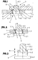
- FIG. 1 1 and 2 are two of metal, such as steel sheet produced by stamping and bending workpieces or components that are connected to each other via a hinge 3 and of which the component 1 is made for example by punching from a metallic sheet, for example made of sheet steel, in a follower or step tool arranged in a press.
- the component 2 is for example an element of a linkage, which is connected via the joint 3 articulated to the component 1.
- the joint 3 consists of a slide bearing or joint bushing 5 inserted into an opening 4 of the component 1 and consisting of a thin metal suitable for joint bushings, for example of steel with a sleeve-like bushing body 5.1 and a protruding flange 5.2.
- the bushing 5 is inserted into the opening 4 in such a way that it rests with the flange 5.2 on a surface side of the component 1 facing away from the component 2 at the edge of the opening 4 and is received in the opening 4 with the bush-shaped section 5.
- the joint 3 further consists of the hinge pin 6, which has a bolt head 6.1 and then to this a bolt section 6.2 with a larger diameter and then a bolt section 6.3 with a reduced diameter.
- the bolt section 6.2 of the hinge pin 6 is received in the socket 5, in such a way that the bolt head 6.1 bears against the flange-shaped section 5.2.
- the section 6.3 engages the hinge pin 6 in an opening 7 of the component 2 and is there by riveting, for example, anchored in a tumble-rivet method.
- the components 1 are manufactured, as stated, in a follow-up or step tool provided in a working device, for example a press, in which the components 1 are produced in several working steps, for example by punching and forming, and in this case are u.a. also the opening 6 is introduced into the respective component 1.
- a follow-up or step tool provided in a working device, for example a press, in which the components 1 are produced in several working steps, for example by punching and forming, and in this case are u.a. also the opening 6 is introduced into the respective component 1.
- this follow-up or step tool is also the introduction of the sockets 5, the folding of the respective socket edge 5.3, calibrating the sockets 5 with a suitable calibration tool or mandrel to ensure an exact inner diameter of the sockets 5, the insertion of the respective hinge pin 6 in an inserted in a component 1 socket 5 and securing the hinge pin 6 in the respective socket 5, in such a way that the hinge pin 6, although rotatably received in the respective socket 5, but against falling out of the socket 5 is secured.
- FIG. 2 shows the state achieved after these steps, wherein the securing of the respective hinge pin 6 is achieved in this embodiment by a slight plastic deformation (caulking) of the material of the hinge pin in the region of the stage between the bolt sections 6.2 and 6.3, so that the bolt at this stage a slightly over the circumference of the bolt portion 6.2 away standing annular portion 8 forms, however, in the of the chamfer 4.1 formed extension of the socket 5 is added.
- the bolt section 6.3 facing end or annular surface of the section 8 is in a plane with the component 1 facing away from the surface of the socket edge 5.3.
- To form the portion 8 of the hinge pin 6 is corresponding to the FIG.
- annular projection 8.1 is formed in this embodiment in that in the transition between the bolt sections 6.2 and 6.3 forming and arranged in the plane perpendicular to the bolt longitudinal axis annular surface a bolt portion 6.3 immediately surrounding annular groove 8.2 is formed.
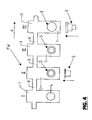
- FIG. 4 shows in a schematic representation again the procedure described above, in which the individual, for example, made of a steel sheet by bending and punching components 1 in the direction of arrow A and moves in time with the machine or the press through the individual sections of the follower or step tool become.
- the insertion of the sockets takes place in the respective opening 4 of a component 1.
- the tool section III then takes place the folding of the edge 5.3 as well as the calibration of the respective bush 5.
- the tool section IV then finally the joining and securing of the respective hinge pin 6.
- the components 1 are in their movement through the following or step tool or through the individual tool sections on material webs or material sections joined together, as shown in the FIG. 4 is indicated schematically with 9.
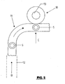
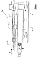
- a Buchsensetzkopf For joining the sockets 5 is a Buchsensetzkopf, in the Figures 5 and 6 is indicated schematically with 10.
- This Buchsensetzkopf 10 which essentially corresponds to a person skilled in the art under the name "punching head” known tool, or a rigid guide 11 of Buchsensetzkopfes 10, the sockets 5 are arranged by a outside of the follower or step tool or the press supply unit via a hose 12 supplied with conveying air, in accordance with the arrow B such that the sockets 5 are arranged in the rigid guide 11 adjacent to each other and oriented with their bushing axes perpendicular to the conveying direction B.
- the sleeve 5 which is provided at the front end in the conveying direction B, is moved out of the guide 11 into a provisioning position 13, as indicated by the arrow C. From the ready position 13, the bush is then inserted axially into the opening 4 of the respective component 1 with a punch or plunger 14 controlled by the movement of the follower or step tool or the press.
- FIG. 6 are also the counter-rotating tool parts W1, W2 and W3 of the follower tool FW and provided on the tool part W2 Buchsensetzkopf 10 with the cooperating with the tool part W1 plunger 14 and the inserted into the component 1 socket 5 are shown schematically.
- the rigid guide 11 has a curvature of about 90 °, in a plane perpendicular to the axial direction of the individual sockets and thus also perpendicular to the joining direction.
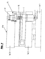
- the folding of the socket edge 5.3 and the calibration of the sockets takes place in the in the FIG. 7 schematically illustrated calibration and Umlegwerkmaschine, which is also provided in the follower tool FW or on one of the tool parts of the follower tool FW and essentially from the calibration and Umlegst Congressel 16 and an actuating element 17 is. While the joining of the respective bushing 5 takes place, for example, from below, the calibration and flipping of the bushing edge with the plunger 16 takes place from above.
- the bushes 5 are formed thin-walled and are therefore subject to a relatively small force an undesirable, for example, the ease of movement of the respective joint impairing deformation. Furthermore occur in the follow-up tool not inconsiderable Tolleranzen u.a. with regard to the positioning of the components 1 at the tool sections, at which the joining of the sockets 5 as well as the calibration and folding of the socket edge 5.3 takes place, i. on the setting head 10 and on the calibration and Umlegewerkmaschine 15.
- This floating bearing for the tools is achieved, for example, in that the cooperating with the respective sleeve 5 end portion of the plunger 14 and cooperating with the respective socket 5 end of the Plunger 16 is pivotally connected to the remaining plunger 14 and plunger 16.
- This directly cooperating with the respective bushing 5 part of the plunger 14 and the plunger 16 then has a short axial length, so that it is not in the processing of the respective socket 5 to tilting or tilting of the cooperating with the socket 5 tool section and thus not to an undesirable deformation of the socket 5 comes.
- the cooperating with the respective bush tool portion has a low weight or a small mass.
- FIG. 8 shows very schematically the process flow in a further possible embodiment of the invention, in which the respective bush 5 is pre-assembled with the associated hinge pin 6 in the respective component 1 is used. According to the presentation of the FIG. 8 this is done so that the sockets 5 and the hinge pin 6 are each provided separately in a supply. During the processing process, a socket 5 and a hinge pin 6 are then brought together outside the follower or step tool and fed in this form the corresponding setting head for inserting the bushes / hinge pin combination in the opening 4 of the relevant component 1. For example, in the same tool section of the follower tool FW, the folding of the bushing edge 5.3 and the securing of the hinge pin 6 by caulking or other suitable manner.
- FIG. 9 shows in a simplified representation a section through the component 1 in the region of the opening 4, in the position a after the punching of the component 1 and after the introduction of the openings 4.
- FIG. 10 shows again in detail the in connection with the FIG. 2 already described generally method steps for introducing the Gleitlager- or joint bushing 5 in the component 1, for calibrating and fixing this socket and for inserting and securing the hinge pin 6 in the socket.
- the position a) shows the component 1 together with the already inserted into this component or the opening 4 joint bushing 5 and with a calibration and Umlegst Congressel 18, of which the two sections 18.1 and 18.2 are shown and with the section 18.2 for Calibration of the socket 5 is introduced into this, and that of the umzustegenden bush edge 5.3 having side of this socket forth.
- With a counter tool 19, the component 1 and the joint bushing 5 are supported on the flange-shaped bushing section 5.2.
- the matrix-like counter-tool 19 forms an opening 20 for receiving the portion 18.2.
- the opening 20 has at its the component 1 facing the opening edge an extension 21, and that for receiving the female section 5.2. With the calibration and Umlegst Congressel 18 also takes place a first partial folding of the socket edge 5.3.
- the calibration and Umlegst Schemeel 18 at section 18.2 is provided with a conically tapered portion 18.2.1, to which in the direction of the free end of the calibration and Umlegst Schemeels 18 first a reduced diameter, waisted portion 18.2.2, thereafter the serving to calibrate the inner diameter of the sliding or bearing bushing 5 section 18.2.3 with circular cylindrical outer surface and then the free end of the calibration and Umlegst Schemeels 18 forming, frusto-conical tapered section 18.2.4 connect. All sections are formed rotationally symmetrical on its peripheral surface and indeed coaxially with the longitudinal axis L St18 of the calibration and Umlegst formulateels 18th
- the complete folding of the socket edge 5.3 is carried out according to the position b) of FIG. 10 with a Umlegst Congressel 22, inter alia, a ram portion 22.1 having a large outer diameter and the ram forming, reduced in outer diameter portion 22.2, which is shaped similar to the portion 18.2, starting from the ram portion 22.1 to the free end of the Umlegst Schemeels 22 with a constricted or waisted portion 22.2.1, with a circular cylindrical outer surface having portion 22.2.2 and with a free end of the Umlegst formulateels 22 forming and tapering towards this end truncated section 22.2.3.
- annular surface 23 is formed, which lies in a plane perpendicular to the ram longitudinal axis L St22 and with the insertion of the ram portion 22.2 in the plain bearing or joint bushing 5 of the sleeve edge 5.3 is completely folded.
- the component 1 and the sliding or bearing bush 5 are in turn supported on the counter tool 19.
- the position c) of FIG. 10 used in the secured in the component 1 sliding bearing or joint bushing 5 of the hinge pin 6, so that its bolt portion 6.2 is received in the socket 5.
- the hinge pin 6 is in the context of the FIG. 3 described annular projection 8.1 provided.
- the axial distance that the free edge of the projection 8.1 from the level of the bolt sections 6.2 and 6.3 facing 6.1.1 side of the bolt head is taking into account the component tolerances, ie in particular taking into account the tolerances of the thickness of the component 1, the thickness or Material thickness of Gleitlager- or joint bushings 5 and the axial length of the bolt portion 6.2 with the projection 8.1 selected such that this projection slightly protrudes with its free edge after insertion of the hinge pin 6 on the plane of the component 1 side facing away from the female section 5.2, as this is indicated by the dimension X in the position c).
- FIG. 10 The securing of the hinge pin 6 in the sliding bearing or joint bushing 5 by caulking or by plastic partial deformation of the projection 8.1 in the in position d) the FIG. 10 shown way.
- a tool is used, which consists of the punch 23, which abuts against the bolt head 6.1 or against the bolt sections 6.2 and 6.3 facing away from the top 6.1.2, and from the die-like counter tool 24.
- the counter tool 24 forms an opening 25 for receiving the pin section 6.3.
- the opening 25 is provided on the component 1 side facing, ie on the bearing or support surface 27 of the counter tool 24 with an extension 26, in such a way that in this extension of the socket section is added 5.2 and so when caulking the projection 8.1 no or substantially no forces are exerted on this bushing section, yet the desired caulk or plastic deformation of the projection 8.1 is carried out.
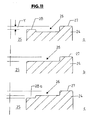
- the extension 26 is provided at its bottom with an opening 25 enclosing the annular elevation 28, which is set back slightly in the illustrated embodiment with respect to the plane of the contact surface 27, that does not project beyond the plane of the contact surface 27, but from this plane to the in the FIG. 10 , Position d) and in the FIG. 11 in the position a) in each case with Y designated measure is spaced.
- the projection 8.1 is caulked such that the annular securing section 8 is spaced from the plane of the underside of the socket section 5.2 facing away from the component 1, ie offset in relation to this plane in the direction of the bolt head 6.1 is. This is again possible because the opening 4 is provided with the chamfered area or chamfer 4.1.
- FIG. 11 shows, by appropriate design of the counter tool 24 in the region of the opening 25 enclosing extension 26 the ability to make the caulking so that the bolt head 6.1 facing away from surface of the annular securing portion 8 in a common plane with the component 1 facing away from the underside of the socket portion 5.2, for which the counter-tool in the region of the extension 26 does not have the ring-like projection 28 ( FIG. 11 Position b), or projecting beyond this plane, for which the counter tool 24 in the region of the extension 26 instead of the projection 28 has an opening 25 enclosing annular recess 28 a ( FIG. 11 , Position c)).
- the projection 8.1 enclosing the axial length of the bolt portion 6.2 is selected so that it is at least equal to the sum of the material thickness of the component 1, the double thickness of the Leitlager- or joint bushing 5 plus the tolerances of the component 1 and the double wall thickness of Plain bearing or joint bushing 5 is.
- the caulking is to take place only in the region of the projection 8.1, it is still sufficient for securing the hinge pin 6, if the height H or axial dimension of the projection 8.1 at least equal to the sum of the tolerances of the thickness of the component 1 and the double tolerance of Wall thickness of the plain bearing or joint bushing 5, wherein in such cases in which the securing portion 8 produced by the caulking is performed backward, ie relative to the plane of the component 1 side facing away from the socket section 5.2 is reset, can still be reduced beyond this didacticsteh measure, while the case that the fuse portion 8 produced by caulking projects over the socket section 5.2, the height H of the projection 8.1 still to this protruding dimension is increased.
- the projection 8.1 is furthermore designed in each case such that the volume of the supernatant X (position C of FIG. 10 ) is not larger or not substantially larger than the free space available for caulking the projection 8.1, ie substantially formed by the chamfer 4.1.
- the caulking of the projection 8.1 in any case, however, so that this projection is not deformed over its entire height H, but only a small part of its height, for example, to a maximum of 20 % of its height H in the area of the free edge.
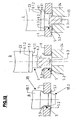
- FIG. 12 shows in positions a) and b) one opposite the FIG. 10 simplified method for fixing the sliding or bearing bush and for setting and securing the hinge pin 6.
- the position a) of FIG. 12 corresponds to position a) of FIG. 10 , ie in this position, in turn, the calibration of the plain bearing and joint bushing 5 and the partial folding of the bushing edge 5.3 with the calibration and Umlegst Congressel 18 is shown.
- the insertion and fixing of the plain bearing or joint bushing 5 and the setting and securing of the hinge pin 6 takes place in this embodiment again under or in the press and in a production tool, such as progressive or step tool, which is also for producing at least the component. 1 for example, by punching and bending serves.
- a production tool such as progressive or step tool, which is also for producing at least the component. 1 for example, by punching and bending serves.
- at least the tools used to insert, calibrate and fix the plain bearing and joint bushings 5 are in turn movable, i. stored in particular floating or suspension, so that there is a force-controlled movement for these tools instead of the path-controlled movement of the press.
- the in connection with the Figures 10 - 12 described method can also preferably with the in the FIG. 9 described method for calibrating the material thickness of the component 1 are combined, that is, before setting the respective plain bearing or joint bushing by plastic deformation
- This component thickness calibration so that in particular even when caulking the hinge pin is not caused by tolerances deformation of the material thickness of the socket edge 5.3 even unsprung Verstemmtechnikmaschineen (punch 23 and counter tool 24).
- the hinge pins 6 have a ring-like projection 8. It goes without saying that it is also possible, instead of a ring-like projection, to use a differently shaped projection or else several e.g. to provide projections distributed around the axis of the hinge pin 6.
Landscapes
- Engineering & Computer Science (AREA)
- Mechanical Engineering (AREA)
- General Engineering & Computer Science (AREA)
- Automatic Assembly (AREA)
- Insertion Pins And Rivets (AREA)
- Pivots And Pivotal Connections (AREA)
- Connection Of Plates (AREA)
Applications Claiming Priority (4)
| Application Number | Priority Date | Filing Date | Title |
|---|---|---|---|
| DE102006020601 | 2006-05-02 | ||
| DE102006031616.9A DE102006031616B4 (de) | 2006-05-02 | 2006-07-06 | Verfahren zum Herstellen eines Gelenks |
| DE102006050463.1A DE102006050463B4 (de) | 2006-05-02 | 2006-10-20 | Verfahren zum Herstellen eines Gelenks |
| EP07008744.0A EP1852212B1 (fr) | 2006-05-02 | 2007-04-30 | Procédé de fabrication d'une articulation, articulation ansi qu'un axe d'articulation |
Related Parent Applications (3)
| Application Number | Title | Priority Date | Filing Date |
|---|---|---|---|
| EP07008744.0 Division | 2007-04-30 | ||
| EP07008744.0A Division EP1852212B1 (fr) | 2006-05-02 | 2007-04-30 | Procédé de fabrication d'une articulation, articulation ansi qu'un axe d'articulation |
| EP07008744.0A Division-Into EP1852212B1 (fr) | 2006-05-02 | 2007-04-30 | Procédé de fabrication d'une articulation, articulation ansi qu'un axe d'articulation |
Publications (3)
| Publication Number | Publication Date |
|---|---|
| EP2204257A2 true EP2204257A2 (fr) | 2010-07-07 |
| EP2204257A3 EP2204257A3 (fr) | 2016-11-09 |
| EP2204257B1 EP2204257B1 (fr) | 2018-07-11 |
Family
ID=38171132
Family Applications (2)
| Application Number | Title | Priority Date | Filing Date |
|---|---|---|---|
| EP07008744.0A Active EP1852212B1 (fr) | 2006-05-02 | 2007-04-30 | Procédé de fabrication d'une articulation, articulation ansi qu'un axe d'articulation |
| EP10003406.5A Not-in-force EP2204257B1 (fr) | 2006-05-02 | 2007-04-30 | Procédé de fabrication d'une articulation, articulation ansi qu'un axe d'articulation |
Family Applications Before (1)
| Application Number | Title | Priority Date | Filing Date |
|---|---|---|---|
| EP07008744.0A Active EP1852212B1 (fr) | 2006-05-02 | 2007-04-30 | Procédé de fabrication d'une articulation, articulation ansi qu'un axe d'articulation |
Country Status (6)
| Country | Link |
|---|---|
| US (2) | US7979967B2 (fr) |
| EP (2) | EP1852212B1 (fr) |
| CA (1) | CA2587078C (fr) |
| DE (2) | DE102006031616B4 (fr) |
| ES (2) | ES2638048T3 (fr) |
| PL (1) | PL1852212T3 (fr) |
Cited By (1)
| Publication number | Priority date | Publication date | Assignee | Title |
|---|---|---|---|---|
| DE102016111708A1 (de) | 2016-06-27 | 2017-12-28 | Heiko Schmidt | Gelenkanordnung, vorgefertigte Baugruppe sowie Verfahren zur Herstellung einer vorgefertigten Baugruppe einer Gelenkanordnung |
Families Citing this family (15)
| Publication number | Priority date | Publication date | Assignee | Title |
|---|---|---|---|---|
| DE202005005827U1 (de) * | 2005-04-11 | 2005-06-16 | Igus Gmbh | Gleitlager und Gleitlagersystem |
| DE102005057010B4 (de) * | 2005-11-30 | 2011-12-22 | Magna Car Top Systems Gmbh | Gelenkvorrichtung, bestehend aus zwei relativbeweglichen Elementen |
| DE102009031050B4 (de) * | 2009-06-30 | 2016-02-11 | Magna Car Top Systems Gmbh | Gelenkeinrichtung zwischen Lenkern eines Gestänges eines Faltverdecks |
| EP2469351A1 (fr) * | 2010-12-22 | 2012-06-27 | Nivarox-FAR S.A. | Assemblage d'une pièce ne comportant pas de domaine plastique |
| DE102011113748B4 (de) * | 2011-09-14 | 2019-05-02 | Adient Luxembourg Holding S.À R.L. | Verfahren zur Herstellung eines Fahrzeugsitz-Beschlags |
| EP2906844B1 (fr) * | 2012-09-30 | 2021-05-05 | Saint-Gobain Performance Plastics Corporation | Ensemble de palier |
| DE102014110139A1 (de) * | 2014-05-27 | 2015-12-03 | Heiko Schmidt | Verfahren zur Herstellung einer Nietverbindung zwischen einem Kugelgelenkbolzen und einem blechförmigen Bauteil sowie zugehörige vorgefertigte Baugruppe |
| CN109068795B (zh) | 2016-03-15 | 2022-02-22 | 耐克创新有限合伙公司 | 用于鞋制品的鞋底结构 |
| US9897136B1 (en) * | 2016-11-04 | 2018-02-20 | Hanwit Precision Industries Ltd. | Hinge |
| TWM540935U (zh) * | 2016-11-17 | 2017-05-01 | Ting-Jui Wang | 旋動結構 |
| DE102016123297B4 (de) | 2016-12-02 | 2019-03-28 | Lohr Technologies Gmbh | Gelenk |
| DE102017211385A1 (de) * | 2017-07-04 | 2019-01-10 | Mahle International Gmbh | Verfahren zur Herstellung einer Rollenlagerung |
| TWI661134B (zh) * | 2018-06-04 | 2019-06-01 | Hanwit Precision Industries Ltd. | Positioning device and assembly method thereof |
| DE102019113847B3 (de) * | 2019-05-23 | 2020-03-26 | Benteler Automobiltechnik Gmbh | Lageranordnung |
| DE102023208708B3 (de) | 2023-09-08 | 2025-02-13 | Magna Car Top Systems Gmbh | Befestigungssystem einer Kinematikbaugruppe zur Anbindung an ein Karosseriebauteil eines Fahrzeugs |
Family Cites Families (27)
| Publication number | Priority date | Publication date | Assignee | Title |
|---|---|---|---|---|
| US2292467A (en) * | 1937-10-22 | 1942-08-11 | Norsell Knut Birger | Means for anchoring pins into metallic members |
| US2264747A (en) * | 1941-05-26 | 1941-12-02 | Donald W Fether | Tubular rivet |
| US2556449A (en) * | 1946-01-05 | 1951-06-12 | Buffalo Wire Works Co Inc | Pivot joint |
| US3588990A (en) * | 1969-01-16 | 1971-06-29 | Ibm | Manufacturing technique of self-punch and self-clinch component assembly |
| US3848389A (en) * | 1969-12-29 | 1974-11-19 | Textron Inc | Bimetal rivets |
| US3766599A (en) * | 1971-07-30 | 1973-10-23 | Mullins Mf Co | Button hinge |
| NZ196479A (en) * | 1981-03-12 | 1984-02-03 | Interlock Ind Ltd | Friction pivot joint for stay |
| GB2193931B (en) * | 1986-07-15 | 1991-03-13 | Honda Motor Co Ltd | Method of and mechanism for attaching automobile door |
| US5205016A (en) * | 1986-09-06 | 1993-04-27 | Ed. Scharwachter Gmbh & Co. Kg | Door holding device |
| SE501526C2 (sv) * | 1992-08-27 | 1995-03-06 | Bjoern Keding | Metod att härda lackerade skivmaterial med elektronstrålning |
| DE9409285U1 (de) * | 1994-06-08 | 1995-10-05 | Ed. Scharwächter GmbH + Co KG, 42855 Remscheid | Scharnierstiftloses wartungsfrei gelagertes Blechscharnier für Kraftwagentüren |
| US5577295A (en) * | 1994-09-27 | 1996-11-26 | Chrysler Corporation | Three diameter hinge pin |
| US5735021A (en) * | 1997-02-18 | 1998-04-07 | Allen-Stevens Corp. | Snap stud assembly |
| US6238127B1 (en) * | 1998-12-17 | 2001-05-29 | Western Sky Industries, Inc. | Pivot apparatus including a fastener and bushing assembly |
| US6171011B1 (en) * | 1999-01-05 | 2001-01-09 | Yu-Chih Wu | Structure of pivot joint |
| DE19944674C2 (de) * | 1999-09-17 | 2001-07-19 | Ks Gleitlager Gmbh | Gleitlagerung und Verfahren zu seiner Herstellung |
| DE19945371A1 (de) * | 1999-09-22 | 2001-04-26 | Ks Gleitlager Gmbh | Gleitlagerung |
| US6418590B1 (en) * | 2000-07-03 | 2002-07-16 | Juanda J. Nipper | Bifold door fitting |
| DE10114200A1 (de) * | 2001-03-23 | 2002-09-26 | Profil Verbindungstechnik Gmbh | Funktionselement, Zusammenbauteil bestehend aus einem Blechteil und einem Funktionselement sowie Verfahren zur Anbringung eines Funktionselementes an ein Blechteil |
| US6499926B2 (en) * | 2001-05-18 | 2002-12-31 | The Boeing Company | Fastener apparatus and method of fastening non-metallic structures |
| DE10230589B4 (de) * | 2002-07-05 | 2012-05-10 | C. Rob. Hammerstein Gmbh & Co. Kg | Spielfreies Gelenk für Kraftfahrzeugsitze |
| DE10241701A1 (de) * | 2002-09-09 | 2004-03-18 | Profil Verbindungstechnik Gmbh & Co. Kg | Verfahren sowie Matrize zur Anbringung eines Funktionselements an ein Blechteil |
| DE102004031379A1 (de) * | 2003-07-25 | 2005-02-10 | Profil Verbindungstechnik Gmbh & Co. Kg | Verfahren zur Anbringung eines Funktionselementes an ein Bleichteil sowie Zusammenbauteil |
| DE202005005827U1 (de) * | 2005-04-11 | 2005-06-16 | Igus Gmbh | Gleitlager und Gleitlagersystem |
| DE102005057010B4 (de) | 2005-11-30 | 2011-12-22 | Magna Car Top Systems Gmbh | Gelenkvorrichtung, bestehend aus zwei relativbeweglichen Elementen |
| FR2895292B1 (fr) * | 2005-12-26 | 2008-03-14 | Jtm Soc Par Actions Simplifiee | Procede et dispositif de fabrication par emboutissage progressif d'une piece comportant une bague sertie |
| US7509710B1 (en) * | 2008-01-29 | 2009-03-31 | Cheng Uei Precision Industry Co., Ltd. | Damper apparatus |
-
2006
- 2006-07-06 DE DE102006031616.9A patent/DE102006031616B4/de not_active Expired - Fee Related
- 2006-10-20 DE DE102006050463.1A patent/DE102006050463B4/de not_active Expired - Fee Related
-
2007
- 2007-04-30 EP EP07008744.0A patent/EP1852212B1/fr active Active
- 2007-04-30 PL PL07008744T patent/PL1852212T3/pl unknown
- 2007-04-30 ES ES07008744.0T patent/ES2638048T3/es active Active
- 2007-04-30 EP EP10003406.5A patent/EP2204257B1/fr not_active Not-in-force
- 2007-04-30 US US11/797,092 patent/US7979967B2/en not_active Expired - Fee Related
- 2007-04-30 ES ES10003406.5T patent/ES2685500T3/es active Active
- 2007-05-02 CA CA2587078A patent/CA2587078C/fr not_active Expired - Fee Related
-
2011
- 2011-07-18 US US13/184,780 patent/US8671522B2/en not_active Expired - Fee Related
Non-Patent Citations (1)
| Title |
|---|
| None |
Cited By (2)
| Publication number | Priority date | Publication date | Assignee | Title |
|---|---|---|---|---|
| DE102016111708A1 (de) | 2016-06-27 | 2017-12-28 | Heiko Schmidt | Gelenkanordnung, vorgefertigte Baugruppe sowie Verfahren zur Herstellung einer vorgefertigten Baugruppe einer Gelenkanordnung |
| WO2018001613A1 (fr) | 2016-06-27 | 2018-01-04 | Heiko Schmidt | Système d'articulation, module préfabriqué et procédé de fabrication d'un module préfabriqué d'un système d'articulation |
Also Published As
| Publication number | Publication date |
|---|---|
| DE102006031616A1 (de) | 2007-11-08 |
| EP2204257B1 (fr) | 2018-07-11 |
| ES2685500T3 (es) | 2018-10-09 |
| EP2204257A3 (fr) | 2016-11-09 |
| ES2638048T3 (es) | 2017-10-18 |
| CA2587078C (fr) | 2011-07-12 |
| DE102006031616B4 (de) | 2015-05-28 |
| US8671522B2 (en) | 2014-03-18 |
| DE102006050463B4 (de) | 2016-09-15 |
| DE102006050463A1 (de) | 2008-04-24 |
| CA2587078A1 (fr) | 2007-11-02 |
| EP1852212A3 (fr) | 2010-03-10 |
| US7979967B2 (en) | 2011-07-19 |
| US20110271487A1 (en) | 2011-11-10 |
| US20070277346A1 (en) | 2007-12-06 |
| EP1852212A2 (fr) | 2007-11-07 |
| EP1852212B1 (fr) | 2017-08-09 |
| PL1852212T3 (pl) | 2017-10-31 |
Similar Documents
| Publication | Publication Date | Title |
|---|---|---|
| EP2204257B1 (fr) | Procédé de fabrication d'une articulation, articulation ansi qu'un axe d'articulation | |
| EP1068458B1 (fr) | Dispositif d'assemblage pour la jonction de deux composants, combinaison du dispositif d'assemblage avec les deux composants et procede d'obtention d'une jonction entre deux composants | |
| EP0758039B1 (fr) | Rail d'ancrage pour la technique du bâtiment | |
| EP2134585B1 (fr) | Crémaillère ou tige filetée | |
| EP0903507B1 (fr) | Rivet aveugle comportant une tige de rupture et appareil de pose | |
| EP2980426B1 (fr) | Composant d'assemblage comprenant un element a sertir et une partie de tole | |
| DE69007309T2 (de) | Hohlbolzen mit inneren Ausbuchtungen und deren Herstellung. | |
| EP3475589B1 (fr) | Système d'articulation, module préfabriqué et procédé de fabrication d'un module préfabriqué d'un système d'articulation | |
| EP1229254A2 (fr) | Liaison par rivetage poinçonnant et rivet poinçonnant creux | |
| DE4417279A1 (de) | Verfahren zum formschlüssigen Verbinden zweier Bauteile von Verstelleinrichtungen für Kraftfahrzeuge | |
| WO2011018194A1 (fr) | Assemblage par rivets et procédé de production associé | |
| DE102012003737A1 (de) | "Verfahren und Werkzeug zum Verbinden von wenigstens zwei Bauteilen und Verbindungssystem" | |
| EP1642037B1 (fr) | Ensemble palier pour un vehicule automobile | |
| WO2005042182A1 (fr) | Composant hybride et procede de fabrication | |
| DE102015206461A1 (de) | Verfahren zur Umformung eines rohrförmigen Strukturbauteils für Kraftfahrzeugsitze | |
| AT14987U1 (de) | Verfahren zum Verbinden von Möbelbeschlagsteilen und Möbelbeschlag | |
| DE102009025525A1 (de) | Verfahren zum Ausbilden einer Einpressverbindung zwischen einem Fügeelement und einem Werkstück, Einpressverbindung sowie Fügeelement | |
| DE102008023044B4 (de) | Verfahren zum Anbringen eines Füge- oder Funktionselementes an einem plastisch verformbaren Flachmaterial | |
| DE10134439C2 (de) | Schwenkbares Gestänge für ein öffnungsfähiges Fahrzeugdach sowie Verfahren zum Herstellen desselben | |
| DE102005035478B4 (de) | Verfahren und Werkzeug zur Herstellung eines Flansches an einem Buchsenlager | |
| DE102012102951A1 (de) | Verfahren und Vorrichtung zum Fügen eines Nietelements | |
| DE19531016A1 (de) | Verbindungselement, nach Art eines Niets | |
| DE69507582T2 (de) | Kaltgenietetes Zapfenelement | |
| DE102006033279A1 (de) | Verfahren und Vorrichtung zum Verbinden mehrerer Kabel mit einem Bauteil sowie Nietbuchse hierfür | |
| DE102007017030B3 (de) | Verfahren und Vorrichtung zum Herstellen eines Innenhochdruckumformteils |
Legal Events
| Date | Code | Title | Description |
|---|---|---|---|
| PUAI | Public reference made under article 153(3) epc to a published international application that has entered the european phase |
Free format text: ORIGINAL CODE: 0009012 |
|
| AC | Divisional application: reference to earlier application |
Ref document number: 1852212 Country of ref document: EP Kind code of ref document: P |
|
| AK | Designated contracting states |
Kind code of ref document: A2 Designated state(s): AT BE BG CH CY CZ DE DK EE ES FI FR GB GR HU IE IS IT LI LT LU LV MC MT NL PL PT RO SE SI SK TR |
|
| AX | Request for extension of the european patent |
Extension state: AL BA HR MK RS |
|
| PUAL | Search report despatched |
Free format text: ORIGINAL CODE: 0009013 |
|
| AK | Designated contracting states |
Kind code of ref document: A3 Designated state(s): AT BE BG CH CY CZ DE DK EE ES FI FR GB GR HU IE IS IT LI LT LU LV MC MT NL PL PT RO SE SI SK TR |
|
| AX | Request for extension of the european patent |
Extension state: AL BA HR MK RS |
|
| RIC1 | Information provided on ipc code assigned before grant |
Ipc: E05D 5/16 20060101ALN20161004BHEP Ipc: B21K 25/00 20060101ALI20161004BHEP Ipc: F16C 17/10 20060101ALN20161004BHEP Ipc: F16B 19/06 20060101ALN20161004BHEP Ipc: B23P 19/04 20060101ALI20161004BHEP Ipc: F16C 33/08 20060101ALN20161004BHEP Ipc: F16C 43/02 20060101ALN20161004BHEP Ipc: B23P 11/00 20060101ALI20161004BHEP Ipc: F16C 11/04 20060101AFI20161004BHEP Ipc: F16B 5/04 20060101ALN20161004BHEP Ipc: E05D 9/00 20060101ALN20161004BHEP |
|
| STAA | Information on the status of an ep patent application or granted ep patent |
Free format text: STATUS: REQUEST FOR EXAMINATION WAS MADE |
|
| 17P | Request for examination filed |
Effective date: 20170508 |
|
| RBV | Designated contracting states (corrected) |
Designated state(s): AT BE BG CH CY CZ DE DK EE ES FI FR GB GR HU IE IS IT LI LT LU LV MC MT NL PL PT RO SE SI SK TR |
|
| GRAP | Despatch of communication of intention to grant a patent |
Free format text: ORIGINAL CODE: EPIDOSNIGR1 |
|
| STAA | Information on the status of an ep patent application or granted ep patent |
Free format text: STATUS: GRANT OF PATENT IS INTENDED |
|
| RIC1 | Information provided on ipc code assigned before grant |
Ipc: B23P 19/04 20060101ALI20180201BHEP Ipc: F16B 19/06 20060101ALN20180201BHEP Ipc: B23P 11/00 20060101ALI20180201BHEP Ipc: B21K 25/00 20060101ALI20180201BHEP Ipc: F16B 5/04 20060101ALN20180201BHEP Ipc: F16C 33/08 20060101ALN20180201BHEP Ipc: F16C 17/10 20060101ALN20180201BHEP Ipc: F16C 11/04 20060101AFI20180201BHEP Ipc: E05D 9/00 20060101ALN20180201BHEP Ipc: F16C 43/02 20060101ALN20180201BHEP Ipc: E05D 5/16 20060101ALN20180201BHEP |
|
| INTG | Intention to grant announced |
Effective date: 20180216 |
|
| GRAJ | Information related to disapproval of communication of intention to grant by the applicant or resumption of examination proceedings by the epo deleted |
Free format text: ORIGINAL CODE: EPIDOSDIGR1 |
|
| STAA | Information on the status of an ep patent application or granted ep patent |
Free format text: STATUS: REQUEST FOR EXAMINATION WAS MADE |
|
| REG | Reference to a national code |
Ref country code: DE Ref legal event code: R079 Ref document number: 502007016286 Country of ref document: DE Free format text: PREVIOUS MAIN CLASS: B23P0011000000 Ipc: F16C0011040000 |
|
| GRAR | Information related to intention to grant a patent recorded |
Free format text: ORIGINAL CODE: EPIDOSNIGR71 |
|
| GRAS | Grant fee paid |
Free format text: ORIGINAL CODE: EPIDOSNIGR3 |
|
| STAA | Information on the status of an ep patent application or granted ep patent |
Free format text: STATUS: GRANT OF PATENT IS INTENDED |
|
| GRAA | (expected) grant |
Free format text: ORIGINAL CODE: 0009210 |
|
| STAA | Information on the status of an ep patent application or granted ep patent |
Free format text: STATUS: THE PATENT HAS BEEN GRANTED |
|
| INTC | Intention to grant announced (deleted) | ||
| RIC1 | Information provided on ipc code assigned before grant |
Ipc: F16B 19/06 20060101ALN20180529BHEP Ipc: E05D 9/00 20060101ALN20180529BHEP Ipc: F16B 5/04 20060101ALN20180529BHEP Ipc: F16C 43/02 20060101ALN20180529BHEP Ipc: F16C 11/04 20060101AFI20180529BHEP Ipc: F16C 17/10 20060101ALN20180529BHEP Ipc: E05D 5/16 20060101ALN20180529BHEP Ipc: B21K 25/00 20060101ALI20180529BHEP Ipc: F16C 33/08 20060101ALN20180529BHEP Ipc: B23P 11/00 20060101ALI20180529BHEP Ipc: B23P 19/04 20060101ALI20180529BHEP |
|
| AC | Divisional application: reference to earlier application |
Ref document number: 1852212 Country of ref document: EP Kind code of ref document: P |
|
| AK | Designated contracting states |
Kind code of ref document: B1 Designated state(s): AT BE BG CH CY CZ DE DK EE ES FI FR GB GR HU IE IS IT LI LT LU LV MC MT NL PL PT RO SE SI SK TR |
|
| INTG | Intention to grant announced |
Effective date: 20180604 |
|
| REG | Reference to a national code |
Ref country code: GB Ref legal event code: FG4D Free format text: NOT ENGLISH |
|
| REG | Reference to a national code |
Ref country code: CH Ref legal event code: EP |
|
| REG | Reference to a national code |
Ref country code: AT Ref legal event code: REF Ref document number: 1017180 Country of ref document: AT Kind code of ref document: T Effective date: 20180715 |
|
| REG | Reference to a national code |
Ref country code: DE Ref legal event code: R096 Ref document number: 502007016286 Country of ref document: DE |
|
| REG | Reference to a national code |
Ref country code: IE Ref legal event code: FG4D Free format text: LANGUAGE OF EP DOCUMENT: GERMAN |
|
| REG | Reference to a national code |
Ref country code: ES Ref legal event code: FG2A Ref document number: 2685500 Country of ref document: ES Kind code of ref document: T3 Effective date: 20181009 |
|
| REG | Reference to a national code |
Ref country code: NL Ref legal event code: MP Effective date: 20180711 |
|
| REG | Reference to a national code |
Ref country code: LT Ref legal event code: MG4D |
|
| PG25 | Lapsed in a contracting state [announced via postgrant information from national office to epo] |
Ref country code: NL Free format text: LAPSE BECAUSE OF FAILURE TO SUBMIT A TRANSLATION OF THE DESCRIPTION OR TO PAY THE FEE WITHIN THE PRESCRIBED TIME-LIMIT Effective date: 20180711 |
|
| PG25 | Lapsed in a contracting state [announced via postgrant information from national office to epo] |
Ref country code: GR Free format text: LAPSE BECAUSE OF FAILURE TO SUBMIT A TRANSLATION OF THE DESCRIPTION OR TO PAY THE FEE WITHIN THE PRESCRIBED TIME-LIMIT Effective date: 20181012 Ref country code: SE Free format text: LAPSE BECAUSE OF FAILURE TO SUBMIT A TRANSLATION OF THE DESCRIPTION OR TO PAY THE FEE WITHIN THE PRESCRIBED TIME-LIMIT Effective date: 20180711 Ref country code: FI Free format text: LAPSE BECAUSE OF FAILURE TO SUBMIT A TRANSLATION OF THE DESCRIPTION OR TO PAY THE FEE WITHIN THE PRESCRIBED TIME-LIMIT Effective date: 20180711 Ref country code: PL Free format text: LAPSE BECAUSE OF FAILURE TO SUBMIT A TRANSLATION OF THE DESCRIPTION OR TO PAY THE FEE WITHIN THE PRESCRIBED TIME-LIMIT Effective date: 20180711 Ref country code: IS Free format text: LAPSE BECAUSE OF FAILURE TO SUBMIT A TRANSLATION OF THE DESCRIPTION OR TO PAY THE FEE WITHIN THE PRESCRIBED TIME-LIMIT Effective date: 20181111 Ref country code: BG Free format text: LAPSE BECAUSE OF FAILURE TO SUBMIT A TRANSLATION OF THE DESCRIPTION OR TO PAY THE FEE WITHIN THE PRESCRIBED TIME-LIMIT Effective date: 20181011 Ref country code: LT Free format text: LAPSE BECAUSE OF FAILURE TO SUBMIT A TRANSLATION OF THE DESCRIPTION OR TO PAY THE FEE WITHIN THE PRESCRIBED TIME-LIMIT Effective date: 20180711 |
|
| PG25 | Lapsed in a contracting state [announced via postgrant information from national office to epo] |
Ref country code: LV Free format text: LAPSE BECAUSE OF FAILURE TO SUBMIT A TRANSLATION OF THE DESCRIPTION OR TO PAY THE FEE WITHIN THE PRESCRIBED TIME-LIMIT Effective date: 20180711 |
|
| REG | Reference to a national code |
Ref country code: DE Ref legal event code: R097 Ref document number: 502007016286 Country of ref document: DE |
|
| PG25 | Lapsed in a contracting state [announced via postgrant information from national office to epo] |
Ref country code: EE Free format text: LAPSE BECAUSE OF FAILURE TO SUBMIT A TRANSLATION OF THE DESCRIPTION OR TO PAY THE FEE WITHIN THE PRESCRIBED TIME-LIMIT Effective date: 20180711 Ref country code: CZ Free format text: LAPSE BECAUSE OF FAILURE TO SUBMIT A TRANSLATION OF THE DESCRIPTION OR TO PAY THE FEE WITHIN THE PRESCRIBED TIME-LIMIT Effective date: 20180711 Ref country code: IT Free format text: LAPSE BECAUSE OF FAILURE TO SUBMIT A TRANSLATION OF THE DESCRIPTION OR TO PAY THE FEE WITHIN THE PRESCRIBED TIME-LIMIT Effective date: 20180711 Ref country code: RO Free format text: LAPSE BECAUSE OF FAILURE TO SUBMIT A TRANSLATION OF THE DESCRIPTION OR TO PAY THE FEE WITHIN THE PRESCRIBED TIME-LIMIT Effective date: 20180711 |
|
| PLBE | No opposition filed within time limit |
Free format text: ORIGINAL CODE: 0009261 |
|
| STAA | Information on the status of an ep patent application or granted ep patent |
Free format text: STATUS: NO OPPOSITION FILED WITHIN TIME LIMIT |
|
| PG25 | Lapsed in a contracting state [announced via postgrant information from national office to epo] |
Ref country code: SK Free format text: LAPSE BECAUSE OF FAILURE TO SUBMIT A TRANSLATION OF THE DESCRIPTION OR TO PAY THE FEE WITHIN THE PRESCRIBED TIME-LIMIT Effective date: 20180711 Ref country code: DK Free format text: LAPSE BECAUSE OF FAILURE TO SUBMIT A TRANSLATION OF THE DESCRIPTION OR TO PAY THE FEE WITHIN THE PRESCRIBED TIME-LIMIT Effective date: 20180711 |
|
| 26N | No opposition filed |
Effective date: 20190412 |
|
| PG25 | Lapsed in a contracting state [announced via postgrant information from national office to epo] |
Ref country code: SI Free format text: LAPSE BECAUSE OF FAILURE TO SUBMIT A TRANSLATION OF THE DESCRIPTION OR TO PAY THE FEE WITHIN THE PRESCRIBED TIME-LIMIT Effective date: 20180711 |
|
| REG | Reference to a national code |
Ref country code: CH Ref legal event code: PL |
|
| REG | Reference to a national code |
Ref country code: BE Ref legal event code: MM Effective date: 20190430 |
|
| GBPC | Gb: european patent ceased through non-payment of renewal fee |
Effective date: 20190430 |
|
| PG25 | Lapsed in a contracting state [announced via postgrant information from national office to epo] |
Ref country code: LU Free format text: LAPSE BECAUSE OF NON-PAYMENT OF DUE FEES Effective date: 20190430 Ref country code: MC Free format text: LAPSE BECAUSE OF FAILURE TO SUBMIT A TRANSLATION OF THE DESCRIPTION OR TO PAY THE FEE WITHIN THE PRESCRIBED TIME-LIMIT Effective date: 20180711 |
|
| PG25 | Lapsed in a contracting state [announced via postgrant information from national office to epo] |
Ref country code: GB Free format text: LAPSE BECAUSE OF NON-PAYMENT OF DUE FEES Effective date: 20190430 Ref country code: LI Free format text: LAPSE BECAUSE OF NON-PAYMENT OF DUE FEES Effective date: 20190430 Ref country code: CH Free format text: LAPSE BECAUSE OF NON-PAYMENT OF DUE FEES Effective date: 20190430 |
|
| PG25 | Lapsed in a contracting state [announced via postgrant information from national office to epo] |
Ref country code: BE Free format text: LAPSE BECAUSE OF NON-PAYMENT OF DUE FEES Effective date: 20190430 |
|
| PG25 | Lapsed in a contracting state [announced via postgrant information from national office to epo] |
Ref country code: TR Free format text: LAPSE BECAUSE OF FAILURE TO SUBMIT A TRANSLATION OF THE DESCRIPTION OR TO PAY THE FEE WITHIN THE PRESCRIBED TIME-LIMIT Effective date: 20180711 |
|
| PG25 | Lapsed in a contracting state [announced via postgrant information from national office to epo] |
Ref country code: IE Free format text: LAPSE BECAUSE OF NON-PAYMENT OF DUE FEES Effective date: 20190430 |
|
| PG25 | Lapsed in a contracting state [announced via postgrant information from national office to epo] |
Ref country code: PT Free format text: LAPSE BECAUSE OF FAILURE TO SUBMIT A TRANSLATION OF THE DESCRIPTION OR TO PAY THE FEE WITHIN THE PRESCRIBED TIME-LIMIT Effective date: 20181111 |
|
| PGFP | Annual fee paid to national office [announced via postgrant information from national office to epo] |
Ref country code: ES Payment date: 20200629 Year of fee payment: 14 Ref country code: DE Payment date: 20200430 Year of fee payment: 14 Ref country code: FR Payment date: 20200420 Year of fee payment: 14 |
|
| REG | Reference to a national code |
Ref country code: AT Ref legal event code: MM01 Ref document number: 1017180 Country of ref document: AT Kind code of ref document: T Effective date: 20190430 |
|
| PG25 | Lapsed in a contracting state [announced via postgrant information from national office to epo] |
Ref country code: AT Free format text: LAPSE BECAUSE OF NON-PAYMENT OF DUE FEES Effective date: 20190430 |
|
| PG25 | Lapsed in a contracting state [announced via postgrant information from national office to epo] |
Ref country code: CY Free format text: LAPSE BECAUSE OF FAILURE TO SUBMIT A TRANSLATION OF THE DESCRIPTION OR TO PAY THE FEE WITHIN THE PRESCRIBED TIME-LIMIT Effective date: 20180711 |
|
| PG25 | Lapsed in a contracting state [announced via postgrant information from national office to epo] |
Ref country code: HU Free format text: LAPSE BECAUSE OF FAILURE TO SUBMIT A TRANSLATION OF THE DESCRIPTION OR TO PAY THE FEE WITHIN THE PRESCRIBED TIME-LIMIT; INVALID AB INITIO Effective date: 20070430 Ref country code: MT Free format text: LAPSE BECAUSE OF FAILURE TO SUBMIT A TRANSLATION OF THE DESCRIPTION OR TO PAY THE FEE WITHIN THE PRESCRIBED TIME-LIMIT Effective date: 20180711 |
|
| REG | Reference to a national code |
Ref country code: DE Ref legal event code: R119 Ref document number: 502007016286 Country of ref document: DE |
|
| PG25 | Lapsed in a contracting state [announced via postgrant information from national office to epo] |
Ref country code: FR Free format text: LAPSE BECAUSE OF NON-PAYMENT OF DUE FEES Effective date: 20210430 Ref country code: DE Free format text: LAPSE BECAUSE OF NON-PAYMENT OF DUE FEES Effective date: 20211103 |
|
| REG | Reference to a national code |
Ref country code: ES Ref legal event code: FD2A Effective date: 20220727 |
|
| PG25 | Lapsed in a contracting state [announced via postgrant information from national office to epo] |
Ref country code: ES Free format text: LAPSE BECAUSE OF NON-PAYMENT OF DUE FEES Effective date: 20210501 |