EP2204259A2 - Linsenpad, Verfahren zur Herstellung von Linsenpads, Verfahren zur Herstellung von Linsen und Haftelement - Google Patents
Linsenpad, Verfahren zur Herstellung von Linsenpads, Verfahren zur Herstellung von Linsen und Haftelement Download PDFInfo
- Publication number
- EP2204259A2 EP2204259A2 EP09180988A EP09180988A EP2204259A2 EP 2204259 A2 EP2204259 A2 EP 2204259A2 EP 09180988 A EP09180988 A EP 09180988A EP 09180988 A EP09180988 A EP 09180988A EP 2204259 A2 EP2204259 A2 EP 2204259A2
- Authority
- EP
- European Patent Office
- Prior art keywords
- lens
- adhesive layer
- adhesive
- pad
- release sheet
- Prior art date
- Legal status (The legal status is an assumption and is not a legal conclusion. Google has not performed a legal analysis and makes no representation as to the accuracy of the status listed.)
- Withdrawn
Links
- 239000000853 adhesive Substances 0.000 title claims abstract description 87
- 230000001070 adhesive effect Effects 0.000 title claims abstract description 87
- 238000004519 manufacturing process Methods 0.000 title claims abstract description 13
- 239000012790 adhesive layer Substances 0.000 claims abstract description 115
- 238000007688 edging Methods 0.000 claims abstract description 36
- 239000010410 layer Substances 0.000 claims description 55
- 239000000463 material Substances 0.000 claims description 21
- 239000012792 core layer Substances 0.000 claims description 20
- 238000000034 method Methods 0.000 claims description 18
- 229920003023 plastic Polymers 0.000 claims description 6
- 239000004033 plastic Substances 0.000 claims description 6
- 239000011248 coating agent Substances 0.000 claims description 4
- 238000000576 coating method Methods 0.000 claims description 4
- 229920003002 synthetic resin Polymers 0.000 claims description 3
- 239000000057 synthetic resin Substances 0.000 claims description 3
- 239000005871 repellent Substances 0.000 description 46
- 235000019592 roughness Nutrition 0.000 description 31
- 229920000139 polyethylene terephthalate Polymers 0.000 description 20
- 239000005020 polyethylene terephthalate Substances 0.000 description 20
- 230000002093 peripheral effect Effects 0.000 description 15
- 239000002390 adhesive tape Substances 0.000 description 12
- 238000010008 shearing Methods 0.000 description 11
- -1 polyethylene terephthalate Polymers 0.000 description 10
- 230000003746 surface roughness Effects 0.000 description 10
- 238000007493 shaping process Methods 0.000 description 9
- 238000005520 cutting process Methods 0.000 description 6
- 239000000126 substance Substances 0.000 description 6
- 229920001971 elastomer Polymers 0.000 description 5
- 238000007667 floating Methods 0.000 description 5
- 230000003287 optical effect Effects 0.000 description 5
- 239000000123 paper Substances 0.000 description 5
- 239000011247 coating layer Substances 0.000 description 4
- 238000009499 grossing Methods 0.000 description 4
- 239000002985 plastic film Substances 0.000 description 4
- 229920005989 resin Polymers 0.000 description 4
- 239000011347 resin Substances 0.000 description 4
- 238000011156 evaluation Methods 0.000 description 3
- 238000005259 measurement Methods 0.000 description 3
- 238000003825 pressing Methods 0.000 description 3
- XLYOFNOQVPJJNP-UHFFFAOYSA-N water Substances O XLYOFNOQVPJJNP-UHFFFAOYSA-N 0.000 description 3
- 241000511976 Hoya Species 0.000 description 2
- 239000004698 Polyethylene Substances 0.000 description 2
- 239000004743 Polypropylene Substances 0.000 description 2
- NIXOWILDQLNWCW-UHFFFAOYSA-N acrylic acid group Chemical group C(C=C)(=O)O NIXOWILDQLNWCW-UHFFFAOYSA-N 0.000 description 2
- 230000003373 anti-fouling effect Effects 0.000 description 2
- 238000005452 bending Methods 0.000 description 2
- 239000003795 chemical substances by application Substances 0.000 description 2
- 238000011109 contamination Methods 0.000 description 2
- 230000007423 decrease Effects 0.000 description 2
- 238000002474 experimental method Methods 0.000 description 2
- 230000004927 fusion Effects 0.000 description 2
- 239000002184 metal Substances 0.000 description 2
- 229920000573 polyethylene Polymers 0.000 description 2
- 229920005672 polyolefin resin Polymers 0.000 description 2
- 229920001155 polypropylene Polymers 0.000 description 2
- 229920005749 polyurethane resin Polymers 0.000 description 2
- 239000011253 protective coating Substances 0.000 description 2
- 229920002050 silicone resin Polymers 0.000 description 2
- 230000003068 static effect Effects 0.000 description 2
- 238000004381 surface treatment Methods 0.000 description 2
- 238000012360 testing method Methods 0.000 description 2
- 239000004925 Acrylic resin Substances 0.000 description 1
- 229920000178 Acrylic resin Polymers 0.000 description 1
- JOYRKODLDBILNP-UHFFFAOYSA-N Ethyl urethane Chemical compound CCOC(N)=O JOYRKODLDBILNP-UHFFFAOYSA-N 0.000 description 1
- YCKRFDGAMUMZLT-UHFFFAOYSA-N Fluorine atom Chemical compound [F] YCKRFDGAMUMZLT-UHFFFAOYSA-N 0.000 description 1
- 238000005299 abrasion Methods 0.000 description 1
- 238000004873 anchoring Methods 0.000 description 1
- 230000002146 bilateral effect Effects 0.000 description 1
- 238000004061 bleaching Methods 0.000 description 1
- 230000000052 comparative effect Effects 0.000 description 1
- 239000002131 composite material Substances 0.000 description 1
- 239000012141 concentrate Substances 0.000 description 1
- 238000003851 corona treatment Methods 0.000 description 1
- 238000005336 cracking Methods 0.000 description 1
- 230000006866 deterioration Effects 0.000 description 1
- 229910003460 diamond Inorganic materials 0.000 description 1
- 239000010432 diamond Substances 0.000 description 1
- 239000000428 dust Substances 0.000 description 1
- 230000000694 effects Effects 0.000 description 1
- 239000000806 elastomer Substances 0.000 description 1
- 230000002708 enhancing effect Effects 0.000 description 1
- 230000003631 expected effect Effects 0.000 description 1
- 239000012530 fluid Substances 0.000 description 1
- 229910052731 fluorine Inorganic materials 0.000 description 1
- 239000011737 fluorine Substances 0.000 description 1
- 239000006261 foam material Substances 0.000 description 1
- 239000011521 glass Substances 0.000 description 1
- 230000010354 integration Effects 0.000 description 1
- 230000004807 localization Effects 0.000 description 1
- 239000000203 mixture Substances 0.000 description 1
- 150000003961 organosilicon compounds Chemical class 0.000 description 1
- 239000002245 particle Substances 0.000 description 1
- 229920001225 polyester resin Polymers 0.000 description 1
- 239000004645 polyester resin Substances 0.000 description 1
- 238000006116 polymerization reaction Methods 0.000 description 1
- 229920001296 polysiloxane Polymers 0.000 description 1
- 229920005990 polystyrene resin Polymers 0.000 description 1
- 239000004814 polyurethane Substances 0.000 description 1
- 230000003449 preventive effect Effects 0.000 description 1
- 230000001681 protective effect Effects 0.000 description 1
- 210000002374 sebum Anatomy 0.000 description 1
- 229910000077 silane Inorganic materials 0.000 description 1
- 229910001220 stainless steel Inorganic materials 0.000 description 1
- 239000010935 stainless steel Substances 0.000 description 1
- 239000002335 surface treatment layer Substances 0.000 description 1
- 238000010998 test method Methods 0.000 description 1
Images



Classifications
-
- B—PERFORMING OPERATIONS; TRANSPORTING
- B24—GRINDING; POLISHING
- B24B—MACHINES, DEVICES, OR PROCESSES FOR GRINDING OR POLISHING; DRESSING OR CONDITIONING OF ABRADING SURFACES; FEEDING OF GRINDING, POLISHING, OR LAPPING AGENTS
- B24B13/00—Machines or devices designed for grinding or polishing optical surfaces on lenses or surfaces of similar shape on other work; Accessories therefor
- B24B13/005—Blocking means, chucks or the like; Alignment devices
-
- B—PERFORMING OPERATIONS; TRANSPORTING
- B24—GRINDING; POLISHING
- B24B—MACHINES, DEVICES, OR PROCESSES FOR GRINDING OR POLISHING; DRESSING OR CONDITIONING OF ABRADING SURFACES; FEEDING OF GRINDING, POLISHING, OR LAPPING AGENTS
- B24B41/00—Component parts such as frames, beds, carriages, headstocks
- B24B41/06—Work supports, e.g. adjustable steadies
- B24B41/061—Work supports, e.g. adjustable steadies axially supporting turning workpieces, e.g. magnetically, pneumatically
-
- B—PERFORMING OPERATIONS; TRANSPORTING
- B24—GRINDING; POLISHING
- B24B—MACHINES, DEVICES, OR PROCESSES FOR GRINDING OR POLISHING; DRESSING OR CONDITIONING OF ABRADING SURFACES; FEEDING OF GRINDING, POLISHING, OR LAPPING AGENTS
- B24B9/00—Machines or devices designed for grinding edges or bevels on work or for removing burrs; Accessories therefor
- B24B9/02—Machines or devices designed for grinding edges or bevels on work or for removing burrs; Accessories therefor characterised by a special design with respect to properties of materials specific to articles to be ground
- B24B9/06—Machines or devices designed for grinding edges or bevels on work or for removing burrs; Accessories therefor characterised by a special design with respect to properties of materials specific to articles to be ground of non-metallic inorganic material, e.g. stone, ceramics, porcelain
- B24B9/08—Machines or devices designed for grinding edges or bevels on work or for removing burrs; Accessories therefor characterised by a special design with respect to properties of materials specific to articles to be ground of non-metallic inorganic material, e.g. stone, ceramics, porcelain of glass
- B24B9/14—Machines or devices designed for grinding edges or bevels on work or for removing burrs; Accessories therefor characterised by a special design with respect to properties of materials specific to articles to be ground of non-metallic inorganic material, e.g. stone, ceramics, porcelain of glass of optical work, e.g. lenses, prisms
- B24B9/146—Accessories, e.g. lens mounting devices
-
- Y—GENERAL TAGGING OF NEW TECHNOLOGICAL DEVELOPMENTS; GENERAL TAGGING OF CROSS-SECTIONAL TECHNOLOGIES SPANNING OVER SEVERAL SECTIONS OF THE IPC; TECHNICAL SUBJECTS COVERED BY FORMER USPC CROSS-REFERENCE ART COLLECTIONS [XRACs] AND DIGESTS
- Y10—TECHNICAL SUBJECTS COVERED BY FORMER USPC
- Y10T—TECHNICAL SUBJECTS COVERED BY FORMER US CLASSIFICATION
- Y10T156/00—Adhesive bonding and miscellaneous chemical manufacture
- Y10T156/10—Methods of surface bonding and/or assembly therefor
-
- Y—GENERAL TAGGING OF NEW TECHNOLOGICAL DEVELOPMENTS; GENERAL TAGGING OF CROSS-SECTIONAL TECHNOLOGIES SPANNING OVER SEVERAL SECTIONS OF THE IPC; TECHNICAL SUBJECTS COVERED BY FORMER USPC CROSS-REFERENCE ART COLLECTIONS [XRACs] AND DIGESTS
- Y10—TECHNICAL SUBJECTS COVERED BY FORMER USPC
- Y10T—TECHNICAL SUBJECTS COVERED BY FORMER US CLASSIFICATION
- Y10T156/00—Adhesive bonding and miscellaneous chemical manufacture
- Y10T156/10—Methods of surface bonding and/or assembly therefor
- Y10T156/1052—Methods of surface bonding and/or assembly therefor with cutting, punching, tearing or severing
-
- Y—GENERAL TAGGING OF NEW TECHNOLOGICAL DEVELOPMENTS; GENERAL TAGGING OF CROSS-SECTIONAL TECHNOLOGIES SPANNING OVER SEVERAL SECTIONS OF THE IPC; TECHNICAL SUBJECTS COVERED BY FORMER USPC CROSS-REFERENCE ART COLLECTIONS [XRACs] AND DIGESTS
- Y10—TECHNICAL SUBJECTS COVERED BY FORMER USPC
- Y10T—TECHNICAL SUBJECTS COVERED BY FORMER US CLASSIFICATION
- Y10T156/00—Adhesive bonding and miscellaneous chemical manufacture
- Y10T156/10—Methods of surface bonding and/or assembly therefor
- Y10T156/1052—Methods of surface bonding and/or assembly therefor with cutting, punching, tearing or severing
- Y10T156/1062—Prior to assembly
-
- Y—GENERAL TAGGING OF NEW TECHNOLOGICAL DEVELOPMENTS; GENERAL TAGGING OF CROSS-SECTIONAL TECHNOLOGIES SPANNING OVER SEVERAL SECTIONS OF THE IPC; TECHNICAL SUBJECTS COVERED BY FORMER USPC CROSS-REFERENCE ART COLLECTIONS [XRACs] AND DIGESTS
- Y10—TECHNICAL SUBJECTS COVERED BY FORMER USPC
- Y10T—TECHNICAL SUBJECTS COVERED BY FORMER US CLASSIFICATION
- Y10T428/00—Stock material or miscellaneous articles
- Y10T428/14—Layer or component removable to expose adhesive
Definitions
- the present invention relates to a lens pad, a lens pad manufacturing method, a lens manufacturing method, and an adhesive member.
- a water-repellent surface inhibits adhesion of other substances, it naturally inhibits adhesion of adhesive tape as well. In other words, even when adhesive tape is attached onto a water-repellent surface, it readily peels off. In addition, when a force acts on the adhesive surface of the adhesive tape in the direction of shearing, the adhesion of the adhesive tape on the water-repellent surface is readily released, and the attachment portion of the adhesive tape is consequently prone to shift.
- the water-repellent finishing target is spectacle lenses.
- Some kinds of spectacle lenses have undergone water-repellent finishing so as to prevent, e.g., sebum contamination attributed to a touch with the fingers and dust particle contamination.
- a lens manufacturing process in which such a lens is framed in a spectacle frame includes a step of attaching adhesive tape onto a water-repellent surface. Furthermore, in this step, a heavy load is imposed on the adhesive interface. Details of this step will be described below.
- a spectacle lens is manufactured by grinding or cutting the peripheral surface of a round lens (to be also referred to as a target lens or simply referred to as a lens hereinafter) by a rotary edging tool such as a grindstone or a cutter based on the edge shape data of a spectacle frame to shape the lens into an edge shape conforming to the shape of the spectacle frame.
- a rotary edging tool such as a grindstone or a cutter based on the edge shape data of a spectacle frame to shape the lens into an edge shape conforming to the shape of the spectacle frame.
- Edging of a spectacle lens needs not only to conform to the shape of a frame but also to produce optical characteristics involved at positions that follow the owner's prescriptions concerning, e.g., his/her focal position and cylinder axis. In other words, specific regions on a target lens must be shaped into specific shapes.
- Japanese Patent Laid-Open No. 2007-268706 (patent reference 1) describes shaping (edging) of a target lens by a grindstone or a cutter while clamping the convex and concave surfaces of the target lens at the edging center portion using an edging jig attached on a lens rotating shaft.
- the edging jig includes a lens holder onto which the convex surface of the lens is fixed, and a lens retainer which presses the concave surface of the lens.
- a lens pad including adhesive layers on its both surfaces is inserted between the lens holder and the lens, and the lens is fixed onto the lens holder by the adhesive force of the pad. When the lens is stably fixed, it can be shaped into a specific edge shape.
- Japanese Patent Laid-Open No. 2005-111612 (patent reference 2), for example, describes a technique for forming a grinding axial deviation preventive pad from a five-layered body including a first adhesive layer, cushion layer, bond layer, resin film, and second adhesive layer.
- the cushion layer has a thickness of 0.2 to 3 mm, an elongation of 150 to 500%, and a tensile strength of 5 to 200 kg/cm 2 .
- the bond layer has a bonding strength of 2,100 kg/25 mm.
- the resin film has an elongation of 50 to 700% and a tensile strength of 25 to 300 MPa.
- Such a technique described in patent reference 2 adjusts the thickness of the cushion layer to suppress damage inflicted on the lens when it is pressed by a lens fixing jig, and lowers the tensile strength of the cushion layer to suppress a phenomenon in which the adhesive surface floats (peels off) due to a load imposed on it by a rotary tool.
- Japanese Patent Laid-Open No. 2004-330327 (patent reference 3) describes a technique for forming a lens fixing member from a composite adhesive sheet including a flexible double-sided adhesive cushion sheet and flexible single-sided adhesive sheet, brings the adhesion target surface of the single-sided adhesive sheet into press contact with one adhesive surface of the double-sided adhesive cushion sheet, and setting the bonding surface of the single-sided adhesive sheet to have a bonding area larger than that of the bonding surface of the double-sided adhesive cushion sheet.
- the technique described in patent reference 3 damps and absorbs, by the double-sided adhesive cushion sheet, impacts attributed to, e.g., pressing of the lens by the lens fixing jig and ensures a large attachment area of the flexible single-sided adhesive sheet, thereby attaching the cushion sheet onto a water-repellent lens surface.
- the technique described in patent reference 3 allows cutting of a water-repellent lens by stacking sheets of different roles on each other.
- Japanese Patent Laid-Open No. 2004-249454 (patent reference 4) describes a technique associated with adhesive tape having an adhesive surface to come into contact with a lens. This technique adjusts the adhesive force of the adhesive surface of the tape such that its measurement value is 4 gf (0.0392 N) or more when an adhesion test according to the 180-degree peeling method stipulated in ISO29682 "Adhesive Tape/Adhesive Sheet Test Method" is conducted using a polyethylene terephthalate plate, with its surface treated by a fluorosilicone release agent, as a test plate.
- the technique described in patent reference 4 also specifies the adhesion strength of adhesive tape when it is peeled off at 180°. However, it is difficult to obtain an expected effect even by specifying the adhesive strength by its adhesive force acting upon its peel-off because the sheet itself is pressed by the lens fixing jig at the time of lens shaping.
- Patent reference 5 Japanese Patent Laid-Open No. 2006-95657 is characterized by forming a minute opening in the adhesive surface of adhesive tape. Patent reference 5 also describes a mechanism in which the adhesive surface sticks onto the lens surface through the opening upon bonding them.
- Each of the lens pads described in patent references 2 to 4 described above is formed from a layered body including a soft adhesive layer and cushion layer. For this reason, a grinding load and a rotation moment remarkably concentrate on the adhesive surface.
- a lens 3 fixed on a lens holder 1 through a pad 2 is attached onto a lens rotating shaft (not shown) and clamped by both the lens holder 1 and a lens retainer 4, as indicated by a solid line in Fig. 6 , compressive deformation at the central portion of a cushion layer 5 of the pad 2 is large due to an edging load and a clamping pressure (chucking pressure) but that in the outer peripheral portion of the cushion layer 5 is small.
- the present invention has been made to solve the above-mentioned problems, and has as its object to provide a lens pad which allows satisfactory shaping of even a water-repellent lens with a relatively low coefficient of surface friction free from any axial deviation, a method of manufacturing the same, and a lens manufacturing method.
- a lens pad comprising a blank, a first adhesive layer formed on one surface of the blank, and a release sheet which comes into tight contact with a surface of the first adhesive layer to protect the surface, wherein an arithmetic average roughness of a surface of the release sheet on a side of the first adhesive layer is not more than 0.1 ⁇ m, and the surface of the first adhesive layer from which the release sheet is peeled off is attached onto a lens as an edging target.
- the inventors of the present invention paid attention to the influence of the surface roughness of the lens-side adhesive layer 6 on the occurrence of an axial deviation.
- a non-adhesive region attributed to roughness is less likely to form.
- the inventors speculated that the occurrence of floating of adhesive tape is suppressed by exploiting the foregoing fact because the boundary between the adhesive region and the non-adhesive region reduces as a result.
- lens pads with different surface roughnesses were fabricated, and an experiment was conducted using them.
- a lens pad 10 includes a blank 11 and a lens-side adhesive layer (first adhesive layer) 12 and jig-side adhesive layer (second adhesive layer) 13 which are respectively attached on both sides of the blank 11. Release sheets 14 and 15 are attached on the surfaces of the lens-side adhesive layer 12 and jig-side adhesive layer 13, respectively, before the use of the lens pad 10.
- the blank 11 includes a cushion layer 16 and core layer 17. The core layer 17 is inserted between the lens-side adhesive layer 12 and the cushion layer 16.
- the lens pad 10 is formed in a toroid to have a central hole 18 and integrally includes a projection 10a which projects from a part of its outer periphery.
- the projection 10a is gripped by the fingers while the lens pad 10 is peeled off from a lens 3 or a lens holder 20, thus facilitating the peel-off of the lens pad 10.
- the material of the lens-side adhesive layer 12 is appropriately selected in accordance with the edging state of the lens surface.
- a detailed example of that state is the coefficient of static friction of the lens surface.
- an adhesive which forms the adhesive layer 12 does not peel off from the lens 3 during grinding of the lens 3 and can be easily removed after the grinding.
- the adhesive layer 12 is preferably formed from an acrylic or rubber adhesive.
- the thickness of the adhesive layer 12 is preferably 15 to 50 ⁇ m.
- the adhesive force of the adhesive layer 12, which acts on the water-repellent surface is preferably 0.05 to 0.16 N/25 mm, depending on the thickness of the cushion layer 16 used in combination.
- the shearing force of the adhesive layer 12, which acts on the water-repellent surface is preferably 60 to 80 N (Attachment Area: 25 mm ⁇ 25 mm).
- the tensile strength of the adhesive layer 12 (its surface) is preferably 3 to 10 kg/cm 2 and, especially preferably, 4 to 8 kg/cm 2 at an elongation of 10%, depending on the composition of the cushion layer 16 used in combination.
- any axial deviation phenomenon can be suppressed even for a water-repellent lens.
- the surface (adhesive surface) of the adhesive layer 12 on the side of the lens 3 is preferably smooth. More specifically, the arithmetic average roughness of the adhesive surface of the adhesive layer 12 on the side of the lens 3 is preferably 0.1 ⁇ m or less and is more preferably 0.06 ⁇ m or less.
- the surface shape of the release sheet 14 is transferred onto the adhesive surface of the adhesive layer 12.
- the arithmetic average roughness of the surface of the release sheet 14 is preferably 0.1 ⁇ m or less and is more preferably 0.06 ⁇ m or less.
- the release sheet 14 need only be flexible, be hard to crease attributed to bending, and have a roughness that falls within the above-mentioned range on its surface which comes into tight contact with the adhesive layer 12, and the material of the release sheet 14 is not particularly limited.
- a preferable material of the release sheet 14 is, e.g., paper, plastic, metal or glass having a smooth surface which comes into tight contact with the adhesive layer 12.
- a plastic sheet is especially preferable because it is easy to handle.
- a plastic sheet which has its surface smoothed easily and is hard to bend is excellent in protection of the adhesive layer 12.
- the material of the plastic sheet is preferably a polyolefin resin such as polyethylene (PE), polypropylene (PP), or polyethylene terephthalate (PET).
- polystyrene resin, acrylic resin, or cellulosic resin for example, can be used.
- the adhesive layer 12 strongly sticks onto even the water-repellent lens 3.
- the lens 3 can be shaped free from any axial deviation.
- the adhesive surface of the adhesive layer 12 is preferably covered with the release sheet 14 until it is used.
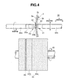
- the material of the jig-side adhesive layer 13 need only be appropriately selected in accordance with the distal end shape and material of a lens retainer 41 ( Fig. 4 ).
- a urethane, acrylic, silicone, or rubber adhesive can be typically adopted, depending on the material of the end face of the lens retainer 41.
- the thickness of the jig-side adhesive layer 13 is preferably 15 to 50 ⁇ m and is especially preferably 20 to 35 ⁇ m.
- the adhesion strength of the adhesive surface of the jig-side adhesive layer 13 is preferably equal to an adhesive force of 5 to 30 N/25 mm for SUS.
- the adhesion strength means the value measured in the same way as in the adhesive layer 12.
- the surface of the jig-side adhesive layer 13 is preferably covered with the release sheet 15 until it is used as well.
- the material of the release sheet 15 is not particularly limited, and can be either known release paper or release film. Also, because the jig-side adhesive layer 13 is not attached onto the lens 3, its surface roughness is not particularly limited, and the jig-side adhesive layer 13 need only have a sufficient adhesive force.
- a material having an elongation of 100 to 500% and an elasticity of 5 to 200 kg/cm 2 is preferably selected for the cushion layer 16.
- the cushion layer 16 has a tensile strength less than 5 kg/cm 2 . This is unpreferable because the cushion layer 16 deformed upon edging is hard to restore its original shape, resulting in an axial deviation.
- the cushion layer 16 has a tensile strength more than 200 kg/cm 2 . This is again unpreferable because the cushion layer 16 is hard to expand, resulting in floating of the lens pad 10 from the lens surface.
- a more preferable tensile strength is 5 to 180 kg/cm 2 .
- the substance of the cushion layer 16 is not particularly limited, it is typically, for example, polyurethane or silicone resin, various types of rubber, various types of elastomers, or foam materials thereof.
- the elongation and tensile strength of the cushion layer 16 represent herein the values measured in conformity with JIS K6767 (method A). Assume that the elongation is lower than 100%. This is unpreferable because strong impacts acting in the first stage of grinding (cutting) cannot be perfectly absorbed, resulting in floating or peel-off of the lens pad 10 from the lens surface. Assume that the elongation is higher than 500%. This is unpreferable because the cushion layer 16 may twist due to even a relatively light edging load in the late stage of edging, resulting in an axial deviation. A more preferable elongation is 110 to 400%.
- the thickness of the cushion layer 16 is preferably 0.5 to 1.5 mm. Assume that the cushion layer 16 has a thickness less than 0.5 mm. In this case, the cushion layer 16 cannot perfectly absorb a chucking pressure attributed to the jig and therefore the load localizes on the lens surface. Load localization is unpreferable because it gives a local impact to the blank 11 or the surface treatment layer of the lens 3. Assume that the cushion layer 16 has a thickness of 1.5 mm or more. This is unpreferable because the cushion layer 16 often twists due to even the grinding (cutting) pressure in the late stage of cutting, resulting in an axial deviation.
- the core layer 17 is not particularly limited as long as it is made of a material which uniformly transfers the pressing load of the lens retainer 41 to the cushion layer 16 and is hard to deform due to a torque transferred during cutting. Hence, the core layer 17 is preferably made of a material harder than that of the cushion layer 16. Although the thickness of the core layer 17 is not particularly limited, it is typically 20 to 100 ⁇ m.
- the core layer 17 is made of, for example, polyester resin, polyolefin resin, silicone resin, or polyurethane resin.
- the core layer 17 having the above-mentioned structure can prevent, e.g., damage inflicted on the pad 10 by keeping the rigidity of the pad 10 itself high.
- the lens-side adhesive layer 6 and core layer 17 are preferably tightly bonded to each other by, e.g., integration that exploits an adhesive or fusion. Both surfaces of the core layer 17 preferably have undergone a surface treatment such as a corona treatment or an anchoring agent treatment so as to enhance the bonding performance between the adhesive layer 12 and the cushion layer 16.
- a bond which bonds the cushion layer 16 and the core layer 17 preferably has a bonding strength of 2 to 100 kg/25 mm.
- the bonding strength represents herein the value measured in conformity with JIS Z1522. If the bonding strength is weaker than 2 kg/25 mm, this is unpreferable because the bond suffers a cohesive failure. If the bonding strength is stronger than 100 kg/25 mm, this is unpreferable because the bond suffers cracking. A more preferable bonding strength is 2 to 80 kg/25 mm.
- the thickness of the bond is not particularly limited, it is typically 1 to 200 ⁇ m. No bond is necessary when the core layer 17 and the cushion layer 16 are integrated with each other by, e.g., fusion.
- the lens 3 is a plastic minus-power lens with a round shape (e.g., Diameter: 80 mm), which is formed by, for example, cast polymerization.
- the lens 3 has the convex-side lens surface (convex surface) 3a, a concave-side lens surface (concave surface) 3b, and an outer peripheral surface (peripheral surface) 3c ( Fig. 3 ).
- a protective coating layer and a water-repellent coating layer are stacked on each of the convex surface 3a and convex surface 3b.
- the protective coating layer is formed so as to improve the optical characteristics, durability, and abrasion resistance of the lens 3, and typically includes a hard coating layer and antireflection coating layer.
- the water-repellent coating layer is formed so as to improve the antifouling performance and prevent any water stain by enhancing the smoothnesses of the optical surfaces 3a and 3b. In recent years, an extreme water-repellent lens with high smoothness is prevailing.
- a water-repellent material containing, for example, an organosilicon compound containing a fluorine-substituted alkyl group is employed as the water-repellent member. Note that the peripheral surface 3c is edged into an edge shape matching the spectacle frame shape by an edging apparatus (to be described later).
- the lens holder 20 will be explained with reference to Figs. 3A to 3C .
- the lens holder 20 is formed into a cylinder by a metal such as stainless steel so as to include a fitting shaft portion 20a and a lens holding portion 20b integrally formed at the distal end of the fitting shaft portion 20a.
- the fitting shaft portion 20a has, for example, a length of 35 mm, an outer diameter of about 14 mm, and a central hole 21 with a diameter of about 10 mm.
- the lens holding portion 20b has a lens holding surface 22 which holds the convex surface 3a of the lens 3.
- the lens holding surface 22 is formed in a concave spherical shape roughly corresponding to the convex surface 3a of the lens 3.
- the central portion of the convex surface 3a of the lens 3 is fixed onto the lens holder 20 through the lens pad 10.
- the edging center of the lens 3 is the spectacle frame center or the optical center of the lens 3.
- the prism measurement reference point of a progressive-power lens or the geometrical center that is nearly the same as the optical center of a single-vision lens, for example, is also preferable as that edging center.
- the radius of curvature of the lens holding surface 22 is set smaller than that of the convex surface 3a so as to bring only the outer peripheral portion of the lens holding surface 22 into contact with the convex surface 3a to stably hold the lens 3.
- the outer diameter of the lens holding portion 20b is nearly equal to that of the lens pad 10.
- the diameter of the central hole 21 is nearly equal to that of the central hole 18 in the lens pad 10.
- a multiple of minute protrusions 23 are radially formed on the lens holding surface 22 throughout its entire periphery so as to enhance the tight bonding force with the lens pad 10.
- the protrusion 23 has an isosceles triangular cross-section so as to form a wall surface 23b on the side of the rotation direction of the lens holder 20 and a wall surface 23c on its opposite side as surfaces inclined at the same angle (e.g., 45°) with respect to a top 23a of the protrusion 23.
- the wall surfaces 23b and 23c have the same inclination angle, the lens pad 10 uniformly comes into tight contact with both the inclined surfaces.
- a lens rotating shaft 30 which mounts the lens 3 includes coaxial horizontal first and second lens rotating shafts 30a and 30b.
- the first lens rotating shaft 30a is rotatably disposed and mounts the lens 3 through the lens holder 20 at its distal end.
- the lens holder 20 is detachably attached onto the first lens rotating shaft 30a by fitting the fitting shaft portion 20a into a fitting hole formed in the distal end surface of the first lens rotating shaft 30a.
- the second lens rotating shaft 30b is disposed to be rotatable and movable in the axial direction (X direction).
- the lens retainer 41 is detachably attached onto the distal end surface, facing the first lens rotating shaft 30a, of the second lens rotating shaft 30b as well.
- An elastic body 42 such as rubber which presses the central portion of the concave surface of the lens 3 is fixed at the distal end of the lens retainer 41.
- the lens rotating shaft 30 including the first and second lens rotating shafts 30a and 30b as mentioned above is controlled to be driven in three directions, i.e., the rotation direction about the shaft line, the horizontal direction (X direction) parallel to the shaft line, and the vertical direction (Y direction) perpendicular to the shaft line based on the shaping data of the lens 3 during edging of the lens 3, thereby grinding the peripheral surface 3c of the lens 3 by a grinding tool 44.
- the grinding tool 44 is, for example, a grindstone such as a cylindrical diamond wheel.
- the grinding tool 44 includes a grindstone 44a for use in primary grinding (coarse grinding) and a grindstone 44b for use in secondary grinding (finish grinding).
- a beveling groove 46 that is a bilateral V-shaped annular groove is formed in the outer peripheral surface of the grindstone 44b for use in secondary grinding.
- the lens 3 is shaped by primary grinding of the peripheral surface 3c of the lens 3 by the grinding tool 44 based on the shaping data of the lens 3 while rotating the lens rotating shaft 30 and grinding tool rotating shaft 45.
- the primary grinding step is a step of forming the lens 3 into a primary shape by coarse grinding of the peripheral surface 3c by the grindstone 44a for use in primary grinding.
- the peripheral surface 3c is continuously ground by the grindstone 44b for use in secondary grinding (secondary grinding) to shape the peripheral surface 3c into an edge shape matching the spectacle frame shape, and the shaping is completed.
- the lens 3 is fixed onto the lens holding surface 22 of the lens holder 20 through the lens pad 10.
- This makes it possible to prevent any axial deviation of the lens 3 during shaping of the lens 3 and, in turn, to shape the lens 3 into a predetermined edge shape. That is, when the central portion of the concave surface of the lens 3 is pressed by the lens retainer 41 to push the convex surface 3a against the lens holding surface 22 of the lens holder 20 through the lens pad 10, the core layer 17 of the lens pad 10 deforms. Because the core layer 17 is a hard layer, it uniformly receives the pressing force of the lens retainer 41 throughout its entire surface and, in turn, uniformly transfers the received force to the cushion layer 16.
- the outer peripheral portion of the lens-side adhesive layer 12 of the lens pad 10 never floats and separates from the convex surface 3a of the lens 3 due to a chucking pressure or a grinding pressure acting on the lens 3. This makes it possible to maintain a large adhesive force and, in turn, to prevent any axial deviation of the lens 3 during grinding.
- the cushion layer 16 of the lens pad 10 twists and deforms in a direction opposite to the rotation direction of the lens rotating shaft 30 due to a grinding load imposed on it during edging to absorb a shearing force inflicted on the interface between the lens 3 and the lens-side adhesive layer 12. This makes it possible to prevent shearing of the lens pad 10. Also, when the thickness of the cushion layer 16 is set to 0.5 mm to 1.5 mm, it is possible to damp a large impact in the initial stage of grinding. This, in turn, makes it possible to satisfactorily shape even a lens with high water repellency free from any axial deviation.
- the lens pad 10 includes the core layer 17 to protect the convex surface 3b of the lens 3 from the lens retainer 41.
- pads respectively including release sheets A, B, C, D, E, F, and G with different surface roughnesses were used to compare and examine the differences in axial deviation performance attributed to the roughnesses of the lens-side adhesive surfaces of the respective release sheets.
- the release sheet A is a transparent sheet made of polyethylene terephthalate, has an arithmetic average roughness of 0.06 ⁇ m, and exhibits a roughness curve with a maximum cross-sectional height of 0.66 ⁇ m.
- the release sheet B is a transparent sheet made of polyethylene terephthalate, has an arithmetic average roughness of 0.02 ⁇ m, and exhibits a roughness curve with a maximum cross-sectional height of 0.184 ⁇ m.
- the release sheet C is a paper sheet and its surface which comes into tight contact with the lens-side adhesive layer is smoothed.
- the smoothed surface of the release sheet C has an arithmetic average roughness of 0.033 ⁇ m and exhibits a roughness curve with a maximum cross-sectional height of 0.332 ⁇ m.
- the release sheet D is a white sheet made of polyethylene terephthalate and its surface which comes into tight contact with the lens-side adhesive layer has an arithmetic average roughness of 0.084 ⁇ m and exhibits a roughness curve with a maximum cross-sectional height of 0.899 ⁇ m.
- the release sheet E is a white sheet made of polyethylene terephthalate as well and its surface which comes into tight contact with the lens-side adhesive layer has an arithmetic average roughness of 0.103 ⁇ m and exhibits a roughness curve with a maximum cross-sectional height of 1.18 ⁇ m.
- Pads respectively including the release sheets F and G are comparative examples.
- the release sheet F is a white sheet made of polyethylene terephthalate and its surface which comes into tight contact with the lens-side adhesive layer has an arithmetic average roughness of 0.12 ⁇ m and exhibits a roughness curve with a maximum cross-sectional height of 2.34 ⁇ m.
- the release sheet G is a paper sheet and its surface which comes into tight contact with the lens-side adhesive layer is smoothed.
- the smoothed surface of the release sheet G has an arithmetic average roughness of 0.15 ⁇ m and exhibits a roughness curve with a maximum cross-sectional height of 1.6 ⁇ m.
- the edging apparatus is set under edging conditions: a load of 3.5 kg is imposed on a lens 3; a lens rotating shaft 30 is rotated at a speed of 5 rpm; and a grinding tool rotating shaft 45 is rotated at a speed of 3,600 rpm.
- a lens pad 10 is of a toroid type having an outer diameter of 22 mm and a central hole 18 with a diameter of 6 mm, and integrally includes a projection 10a in its outer periphery.
- the target lens 3 is a lens (Trade Name: EYAS) manufactured by HOYA and has undergone water-repellent coating (Coefficient of Kinetic Friction: 0.07 to 0.1).
- the uncut lens diameter is 75 mm and the edged lens shape is a binocular half-eye shape (Horizontal Dimension: 54 mm; Vertical Dimension: 26 mm; and Decentering: 5 mm).
- the result shown in Table 1 reveals that the release sheets A to E are desirable as the release sheet 14 and the axial deviation can be kept below 2° when the arithmetic average roughness of the surface, of the release sheet 14, which comes into tight contact with the lens-side adhesive layer 12 is about 0.1 ⁇ m or less and the maximum cross-sectional height of the roughness curve is about 1.0 ⁇ m or less. That result also reveals that an axial deviation phenomenon is preferably suppressed when the arithmetic average roughness of that surface is 0.06 ⁇ m and the maximum cross-sectional height of the roughness curve is 0.7 ⁇ m or less.
- Fig. 5A is a photograph showing the adhesive surface of the lens-side adhesive layer 12 including the release sheet E.
- Fig. 5B is a photograph showing the adhesive surface of the lens-side adhesive layer 12 including the release sheet A.
- the adhesive surface of the lens-side adhesive layer 12 including the release sheet E which is made of a resin and has a relatively rough surface is bleached as compared with that of the lens-side adhesive layer 12 including the release sheet A with a smooth surface.
- the inventors of the present invention speculated that the bleaching is accounted for by diffused reflection of light due to nonuniformity of the adhesive surface. This experimental result reveals that it is hard for the lens pad 10 to come into tight contact with the lens surface when the adhesive surface is rough and therefore an axial deviation phenomenon is prone to occur during edging.
- the edging apparatus is set under edging conditions: a load of 3.5 kg is imposed on a lens 3; a lens rotating shaft 30 is rotated at a speed of 5 rpm; and a grinding tool rotating shaft 45 is rotated at a speed of 3,600 rpm.
- the lens pad 10 is of a toroid type having an outer diameter of 22 mm and a central hole 18 with a diameter of 6 mm, and integrally includes a projection 10a in its outer periphery.
- the target lens 3 is a lens (Trade Name: EYAS) manufactured by HOYA and has undergone water-repellent coating (Coefficient of Kinetic Friction: 0.07 to 0.1).
- the uncut lens diameter is 75 mm and the edged lens shape is a binocular half-eye shape (Horizontal Dimension: 54 mm; Vertical Dimension: 26 mm; and Decentering: 5 mm).
- the above-mentioned measurement result reveals that an axial deviation reduces as the thickness of the cushion layer 16 increases to 0.8 mm or more and the density decreases in the release sheet A with the above-mentioned surface roughness. Also, a pad which has a low density and in which the thickness of the cushion layer 16 is 0.8 mm or less causes a phenomenon in which a part of the cushion layer 16 cracks and remains on a lens holding surface 22 of a lens holder 20. This experimental result reveals that the thickness of the cushion layer 16 is preferably 0.8 mm or more.
- the lens pad 10 mentioned above includes a blank 11, an adhesive layer 12 formed on one surface of the blank 11, and a release sheet 14 which comes into tight contact with the surface of the adhesive layer 12 to protect that surface.
- the arithmetic average roughness of the surface of the release sheet 14 on the side of the adhesive layer 12 is 0.1 ⁇ m or less.
- the surface of the adhesive layer 12 from which the release sheet 14 is peeled off is attached onto a lens 3 as an edging target.
- the surface shape of the release sheet 14 is transferred onto the surface of the adhesive layer 12. For this reason, the surface roughness of the release sheet 14 corresponds to the virtual surface roughness of the adhesive layer 12.
- the arithmetic average roughness of the surface of the adhesive layer 12 is 0.1 ⁇ m or less as in the release sheet 14, it is possible to maintain a good adhesion state between the lens pad 10 and the surface of the lens 3 even when a water-repellent lens 3 with a low surface energy is edged, thus satisfactorily suppressing any axial deviation phenomenon during grinding of the periphery of the lens 3.
- At least the surface of the release sheet 14 on the side of the adhesive layer 12 is preferably made of a synthetic resin. This is because a synthetic resin is more easily formed to have a smooth surface than other materials such as paper materials.
- the release sheet 14 is desirably flexible and hard to crease attributed to bending.
- the adhesive force of the adhesive layer 12 is preferably 0.03 to 0.2 N/25 mm. This makes it possible to satisfactorily suppress any axial deviation phenomenon even when the present invention is applied to a water-repellent lens 3 that is especially hard to grind.
- the lens pad 10 also includes an adhesive layer 13 formed on the other surface of the blank 11 on the side opposite to that of one surface on which the adhesive layer 12 is formed.
- the blank 11 preferably includes an elastic cushion layer 16.
- an elastic cushion layer 16 Although a heavy load is imposed on the lens 3 in the initial stage of its edging because the lens diameter is large in this stage and so a strong force (shearing force) acts on the interface between the lens pad 10 and the surface of the lens 3, this shearing force can be absorbed by the cushion layer 16 by its twisting deformation. This makes it possible to reduce the shearing force directly inflicted on the adhesive region on the lens pad 10 on the lens 3, thus more reliably suppressing any phenomenon in which the surface of the adhesive layer 12 separates from the surface of the lens 3.
- the thickness of the cushion layer 16 is more preferably 0.5 to 1.5 mm.
- the blank 11 preferably moreover includes a core layer 17 made of a material harder than that of the cushion layer 16. Since the core layer 17 is made of a hard material, a chucking pressure or a grinding load can be almost uniformly transferred onto the entire surface of the cushion layer 16. Hence, because the outer periphery of the lens pad 10 never separates and floats from the lens 3 and therefore the adhesive force never reduces, it is possible to effectively suppress any axial deviation phenomenon of the lens 3.
- the core layer 17 is preferably located on the surface of the cushion layer 16 on the side of the adhesive layer 12.
- the blank 11 preferably has a double-layered structure including the cushion layer 16 and core layer 17, it may include only one of these two layers.
- a method of manufacturing a lens pad 10 will be described briefly. First, an adhesive layer 12 is formed by coating a blank 11 with an adhesive material. Next, a release sheet 14 is brought into tight contact with the surface of the adhesive layer 12.
- the release sheet 14 used has an arithmetic average roughness of 0.1 ⁇ m or less on its surface on the side of the adhesive layer 12. Since the surface shape of the release sheet 14 is transferred onto the surface of the adhesive layer 12, the arithmetic average roughness of the adhesive layer 12 also becomes 0.1 ⁇ m or less. This makes it possible to obtain a lens pad 10 having a smooth lens-side adhesive surface.
- a lens pad 10 is prepared. Using the lens pad 10, the central portion of a convex surface 3a of an uncut lens 3 is fixed onto a lens holding surface 22 of a lens holder 20. More specifically, release sheets 14 and 15 are peeled off from the surfaces of adhesive layers 12 and 13 on the lens pad 10, the surface of the adhesive layer 12 is attached at the central portion of the convex surface 3a of the lens 3, and the surface of the adhesive layer 13 is attached onto the lens holding surface 22 of the lens holder 20. Note that the release sheet 14 is preferably peeled off immediately before the adhesive layer 12 is attached onto the lens 3.
- the lens holder 20 on which the lens 3 is fixed is attached onto a lens rotating shaft 30 of an edging apparatus.
- the periphery of the lens 3 is edged into a desired shape. This makes it possible to shape even a water-repellent lens free from any axial deviation phenomenon during the shaping. This method is especially suitable for a plastic lens.
- An adhesive member may have the same structure as that of the lens pad 10. That is, an adhesive member includes a blank 11, an adhesive layer 12 formed on the blank 11, and a release sheet (release member) 14 which comes into tight contact with the surface of the adhesive layer 12 to protect that surface.
- the arithmetic average roughness of the surface of the release sheet 14 on the side of the adhesive layer 12 is 0.1 ⁇ m or less. This adhesive member can strongly stick onto even a water-repellent surface.
- the adhesive member may also include an adhesive layer 13 formed on the other surface of the blank 11 on the side opposite to that of one surface on which the adhesive layer 12 is formed.
- the adhesive member is applicable to, e.g., an indication label attached onto a water-repellent surface, and edging tape.
- an indication label attached onto a water-repellent surface, and edging tape.
- the adhesive member is also applicable to a protective member for a water-repellent article. It is a common practice to protect a water-repellent article by covering its surface with a plastic bag. However, even a water-repellent surface may suffer damage due to a physical impact or a scratch with a sharp object.
- the adhesive member can be preferably brought into tight contact with even a water-repellent surface as well. Hence, the water-repellent surface itself can be protected by employing a relatively hard plastic blank as the blank 11 of the adhesive member.
Landscapes
- Engineering & Computer Science (AREA)
- Mechanical Engineering (AREA)
- Chemical & Material Sciences (AREA)
- Ceramic Engineering (AREA)
- Inorganic Chemistry (AREA)
- Grinding And Polishing Of Tertiary Curved Surfaces And Surfaces With Complex Shapes (AREA)
- Eyeglasses (AREA)
- Lining Or Joining Of Plastics Or The Like (AREA)
- Laminated Bodies (AREA)
Applications Claiming Priority (1)
| Application Number | Priority Date | Filing Date | Title |
|---|---|---|---|
| JP2009000642A JP2010158727A (ja) | 2009-01-06 | 2009-01-06 | レンズ加工用パッド、その製造方法、プラスチックレンズの製造方法および粘着部材 |
Publications (2)
| Publication Number | Publication Date |
|---|---|
| EP2204259A2 true EP2204259A2 (de) | 2010-07-07 |
| EP2204259A3 EP2204259A3 (de) | 2017-06-21 |
Family
ID=42112035
Family Applications (1)
| Application Number | Title | Priority Date | Filing Date |
|---|---|---|---|
| EP09180988.9A Withdrawn EP2204259A3 (de) | 2009-01-06 | 2009-12-30 | Linsenpad, Verfahren zur Herstellung von Linsenpads, Verfahren zur Herstellung von Linsen und Haftelement |
Country Status (4)
| Country | Link |
|---|---|
| US (1) | US8440041B2 (de) |
| EP (1) | EP2204259A3 (de) |
| JP (1) | JP2010158727A (de) |
| CN (1) | CN101850535B (de) |
Cited By (3)
| Publication number | Priority date | Publication date | Assignee | Title |
|---|---|---|---|---|
| EP2565026A1 (de) * | 2011-08-30 | 2013-03-06 | Cerium Group Limited | Mehrlagige Schutzfolie |
| WO2013128096A1 (fr) * | 2012-03-02 | 2013-09-06 | Essilor International (Compagnie Générale d'Optique) | Système comportant un pion de positionnement et de centrage pour lentille ophtalmique, un organe d'assujettissement et un outil pour le positionnement dudit organe d'assujettissement sur ledit pion de positionnement et de centrage |
| US20200023489A1 (en) * | 2018-06-28 | 2020-01-23 | Ebara Corporation | Polishing-pad laminated structure, polishing-pad positioning instrument, and method of attaching a polishing pad to a polishing table |
Families Citing this family (8)
| Publication number | Priority date | Publication date | Assignee | Title |
|---|---|---|---|---|
| JP5765858B2 (ja) * | 2012-12-04 | 2015-08-19 | 丸石産業株式会社 | 研磨パッド |
| JP6257897B2 (ja) * | 2013-01-30 | 2018-01-10 | イーエイチエス レンズ フィリピン インク | 光学物品およびその製造方法 |
| US20160008944A1 (en) * | 2013-03-19 | 2016-01-14 | Jun Zha | Polishing device for optical elements and method thereof |
| DE102014012025A1 (de) * | 2014-08-13 | 2016-02-18 | Rodenstock Gmbh | Einschleifpad mit unterschiedlichen Klebezonen |
| DE102015121682A1 (de) * | 2015-12-14 | 2017-06-14 | Optotech Optikmaschinen Gmbh | Werkstück mit optischem Linsenrohling, Verfahren zu dessen Herstellung und Verfahren zu dessen Bearbeitung |
| KR102233133B1 (ko) * | 2019-05-20 | 2021-03-26 | 양남진 | 실리콘을 이용한 카메라 모듈용 렌즈커버 및 이의 제조방법 |
| CN111482865A (zh) * | 2020-05-25 | 2020-08-04 | 广东长信精密设备有限公司 | 晶圆打磨设备 |
| JP2023133980A (ja) * | 2022-03-14 | 2023-09-27 | リンテック株式会社 | ワーク加工用粘着シート、及び半導体装置 |
Citations (5)
| Publication number | Priority date | Publication date | Assignee | Title |
|---|---|---|---|---|
| JP2004249454A (ja) | 2003-01-27 | 2004-09-09 | Seiko Epson Corp | 粘着テープ及び玉型加工方法 |
| JP2004330327A (ja) | 2003-05-02 | 2004-11-25 | Soken Chem & Eng Co Ltd | レンズの切削・研磨加工に用いるレンズ固定用部材及びそれを用いるレンズの切削・研磨加工方法 |
| JP2005111612A (ja) | 2003-10-08 | 2005-04-28 | Big Technos Kk | フッ素コートメガネレンズ研削用軸ズレ防止パッド |
| JP2006095657A (ja) | 2004-09-30 | 2006-04-13 | Topcon Corp | 眼鏡レンズ取付用粘着シート |
| JP2007268706A (ja) | 2000-02-22 | 2007-10-18 | Hoya Corp | レンズ用レイアウト・ブロック装置 |
Family Cites Families (11)
| Publication number | Priority date | Publication date | Assignee | Title |
|---|---|---|---|---|
| JPH0581248U (ja) * | 1992-03-31 | 1993-11-05 | 日東電工株式会社 | 両面面状粘着体 |
| JP3868114B2 (ja) * | 1998-05-12 | 2007-01-17 | クレハエラストマー株式会社 | 貼着用複合ゴムフィルム |
| JP2001343617A (ja) * | 2000-06-01 | 2001-12-14 | Yoshinari Shimatani | 眼鏡用着色透明再剥離性粘着シート |
| JP5258128B2 (ja) * | 2001-01-24 | 2013-08-07 | 日東電工株式会社 | 加熱剥離型粘着シートの製造方法 |
| KR101016081B1 (ko) * | 2002-07-26 | 2011-02-17 | 닛토덴코 가부시키가이샤 | 점착 시트와 그의 제조방법, 상기 점착 시트의 사용방법,및 상기 점착 시트에 사용되는 다층 시트와 그의 제조방법 |
| JP4204838B2 (ja) * | 2002-10-04 | 2009-01-07 | リンテック株式会社 | オーバーラミ用粘着フィルム |
| JP4875839B2 (ja) * | 2004-07-28 | 2012-02-15 | Hoya株式会社 | プラスチックレンズの製造方法及びプラスチックレンズ |
| EP1803531B1 (de) | 2004-10-15 | 2014-07-23 | Musashi Chemicals Industry Co., Ltd. | Ein Haftklebeband verwendende Verfahren zur Bearbeitung einer Linse |
| CN101189544B (zh) * | 2005-03-03 | 2012-11-07 | 株式会社尼康依视路 | 眼镜用镜片及眼镜用镜片的加工方法 |
| EP1987917A1 (de) * | 2007-05-03 | 2008-11-05 | Saint-Gobain Performance Plastics Corporation | Ophthalmisches Blockierpad |
| JP4673344B2 (ja) | 2007-06-07 | 2011-04-20 | 日東電工株式会社 | 光学フィルム用粘着シートの製造方法 |
-
2009
- 2009-01-06 JP JP2009000642A patent/JP2010158727A/ja active Pending
- 2009-12-30 US US12/650,265 patent/US8440041B2/en active Active
- 2009-12-30 EP EP09180988.9A patent/EP2204259A3/de not_active Withdrawn
-
2010
- 2010-01-06 CN CN2010100014379A patent/CN101850535B/zh active Active
Patent Citations (5)
| Publication number | Priority date | Publication date | Assignee | Title |
|---|---|---|---|---|
| JP2007268706A (ja) | 2000-02-22 | 2007-10-18 | Hoya Corp | レンズ用レイアウト・ブロック装置 |
| JP2004249454A (ja) | 2003-01-27 | 2004-09-09 | Seiko Epson Corp | 粘着テープ及び玉型加工方法 |
| JP2004330327A (ja) | 2003-05-02 | 2004-11-25 | Soken Chem & Eng Co Ltd | レンズの切削・研磨加工に用いるレンズ固定用部材及びそれを用いるレンズの切削・研磨加工方法 |
| JP2005111612A (ja) | 2003-10-08 | 2005-04-28 | Big Technos Kk | フッ素コートメガネレンズ研削用軸ズレ防止パッド |
| JP2006095657A (ja) | 2004-09-30 | 2006-04-13 | Topcon Corp | 眼鏡レンズ取付用粘着シート |
Cited By (7)
| Publication number | Priority date | Publication date | Assignee | Title |
|---|---|---|---|---|
| EP2565026A1 (de) * | 2011-08-30 | 2013-03-06 | Cerium Group Limited | Mehrlagige Schutzfolie |
| US11345113B2 (en) | 2011-08-30 | 2022-05-31 | Cerium Group Limited | Composite protective sheet material |
| WO2013128096A1 (fr) * | 2012-03-02 | 2013-09-06 | Essilor International (Compagnie Générale d'Optique) | Système comportant un pion de positionnement et de centrage pour lentille ophtalmique, un organe d'assujettissement et un outil pour le positionnement dudit organe d'assujettissement sur ledit pion de positionnement et de centrage |
| FR2987572A1 (fr) * | 2012-03-02 | 2013-09-06 | Essilor Int | Systeme comportant un pion de positionnement et de centrage pour lentille ophtalmique, un organe d'assujettissement et un outil pour le positionnement dudit organe d'assujettissement sur ledit pion de positionnement et de centrage |
| US9802287B2 (en) | 2012-03-02 | 2017-10-31 | Essilor International (Compagnie Generale D'optique) | System comprising a positioning and centering pin for an ophthalmic lens, an attachment member and a tool for positioning said attachment member on said positioning and centering pin |
| US20200023489A1 (en) * | 2018-06-28 | 2020-01-23 | Ebara Corporation | Polishing-pad laminated structure, polishing-pad positioning instrument, and method of attaching a polishing pad to a polishing table |
| US11642753B2 (en) * | 2018-06-28 | 2023-05-09 | Ebara Corporation | Polishing-pad laminated structure, polishing-pad positioning instrument, and method of attaching a polishing pad to a polishing table |
Also Published As
| Publication number | Publication date |
|---|---|
| CN101850535A (zh) | 2010-10-06 |
| US20100170627A1 (en) | 2010-07-08 |
| EP2204259A3 (de) | 2017-06-21 |
| CN101850535B (zh) | 2013-06-05 |
| JP2010158727A (ja) | 2010-07-22 |
| US8440041B2 (en) | 2013-05-14 |
Similar Documents
| Publication | Publication Date | Title |
|---|---|---|
| US8440041B2 (en) | Lens pad, lens pad manufacturing method, lens manufacturing method, and adhesive member | |
| CN1546281B (zh) | 镜片保护系统、镜片保护装置和保护镜片的方法 | |
| EP2179818B1 (de) | Schleifartikel | |
| EP2025461B1 (de) | Haftklebefolie und säumverfahren | |
| CN102216407A (zh) | 处理光学透镜用于修边的方法 | |
| US20080149269A1 (en) | Adhesive tape and method for adhering the adhesive tape | |
| US7935402B2 (en) | Ophthalmic blocking pad | |
| CN100519071C (zh) | 固定镜片用的胶带及使用该胶带的镜片加工方法 | |
| US20180236625A1 (en) | Compensating Pad | |
| JP2004330327A (ja) | レンズの切削・研磨加工に用いるレンズ固定用部材及びそれを用いるレンズの切削・研磨加工方法 | |
| JP2004347660A (ja) | 撥油コート付き眼鏡レンズの玉摺加工方法、撥油コート付き眼鏡レンズの製造方法及び粘着剤付テープ | |
| GB2039810A (en) | A Tool Interfacing Pad | |
| JP4141365B2 (ja) | フッ素コートメガネレンズ研削用軸ズレ防止パッド | |
| JP2004148444A (ja) | レンズロックシート | |
| EP1844898B1 (de) | Klotz zur vermeidung von axialer verschiebung für den einsatz beim schleifen von brillenlinsen mit fluorbeschichtung | |
| EP1987917A1 (de) | Ophthalmisches Blockierpad | |
| JP2000042910A (ja) | 研磨用被加工物保持具 | |
| EP4446053A1 (de) | Rohlingkontaktierungselement, vakuumblockierungsstück und verfahren zur herstellung eines brillenglases | |
| WO2006003699A1 (ja) | フッ素コートメガネレンズ研削用軸ズレ防止パッド | |
| HK1119119A (en) | Adhesive tape and method for adhering the adhesive tape |
Legal Events
| Date | Code | Title | Description |
|---|---|---|---|
| PUAI | Public reference made under article 153(3) epc to a published international application that has entered the european phase |
Free format text: ORIGINAL CODE: 0009012 |
|
| AK | Designated contracting states |
Kind code of ref document: A2 Designated state(s): AT BE BG CH CY CZ DE DK EE ES FI FR GB GR HR HU IE IS IT LI LT LU LV MC MK MT NL NO PL PT RO SE SI SK SM TR |
|
| AX | Request for extension of the european patent |
Extension state: AL BA RS |
|
| PUAL | Search report despatched |
Free format text: ORIGINAL CODE: 0009013 |
|
| AK | Designated contracting states |
Kind code of ref document: A3 Designated state(s): AT BE BG CH CY CZ DE DK EE ES FI FR GB GR HR HU IE IS IT LI LT LU LV MC MK MT NL NO PL PT RO SE SI SK SM TR |
|
| AX | Request for extension of the european patent |
Extension state: AL BA RS |
|
| RIC1 | Information provided on ipc code assigned before grant |
Ipc: B24B 9/14 20060101ALI20170515BHEP Ipc: B24B 13/005 20060101AFI20170515BHEP Ipc: B24B 41/06 20120101ALI20170515BHEP |
|
| STAA | Information on the status of an ep patent application or granted ep patent |
Free format text: STATUS: REQUEST FOR EXAMINATION WAS MADE |
|
| 17P | Request for examination filed |
Effective date: 20171221 |
|
| RBV | Designated contracting states (corrected) |
Designated state(s): AT BE BG CH CY CZ DE DK EE ES FI FR GB GR HR HU IE IS IT LI LT LU LV MC MK MT NL NO PL PT RO SE SI SK SM TR |
|
| STAA | Information on the status of an ep patent application or granted ep patent |
Free format text: STATUS: THE APPLICATION HAS BEEN WITHDRAWN |
|
| 18W | Application withdrawn |
Effective date: 20181109 |