EP2204519A1 - Dispositif de porte - Google Patents
Dispositif de porte Download PDFInfo
- Publication number
- EP2204519A1 EP2204519A1 EP08777881A EP08777881A EP2204519A1 EP 2204519 A1 EP2204519 A1 EP 2204519A1 EP 08777881 A EP08777881 A EP 08777881A EP 08777881 A EP08777881 A EP 08777881A EP 2204519 A1 EP2204519 A1 EP 2204519A1
- Authority
- EP
- European Patent Office
- Prior art keywords
- shimmy
- stopping
- door panel
- engaging
- latching mechanism
- Prior art date
- Legal status (The legal status is an assumption and is not a legal conclusion. Google has not performed a legal analysis and makes no representation as to the accuracy of the status listed.)
- Granted
Links
Images





Classifications
-
- E—FIXED CONSTRUCTIONS
- E02—HYDRAULIC ENGINEERING; FOUNDATIONS; SOIL SHIFTING
- E02F—DREDGING; SOIL-SHIFTING
- E02F9/00—Component parts of dredgers or soil-shifting machines, not restricted to one of the kinds covered by groups E02F3/00 - E02F7/00
- E02F9/08—Superstructures; Supports for superstructures
- E02F9/0858—Arrangement of component parts installed on superstructures not otherwise provided for, e.g. electric components, fenders, air-conditioning units
- E02F9/0891—Lids or bonnets or doors or details thereof
-
- E—FIXED CONSTRUCTIONS
- E02—HYDRAULIC ENGINEERING; FOUNDATIONS; SOIL SHIFTING
- E02F—DREDGING; SOIL-SHIFTING
- E02F9/00—Component parts of dredgers or soil-shifting machines, not restricted to one of the kinds covered by groups E02F3/00 - E02F7/00
-
- E—FIXED CONSTRUCTIONS
- E05—LOCKS; KEYS; WINDOW OR DOOR FITTINGS; SAFES
- E05B—LOCKS; ACCESSORIES THEREFOR; HANDCUFFS
- E05B85/00—Details of vehicle locks not provided for in groups E05B77/00 - E05B83/00
- E05B85/02—Lock casings
-
- E—FIXED CONSTRUCTIONS
- E05—LOCKS; KEYS; WINDOW OR DOOR FITTINGS; SAFES
- E05B—LOCKS; ACCESSORIES THEREFOR; HANDCUFFS
- E05B85/00—Details of vehicle locks not provided for in groups E05B77/00 - E05B83/00
- E05B85/04—Strikers
- E05B85/045—Strikers for bifurcated bolts
-
- E—FIXED CONSTRUCTIONS
- E05—LOCKS; KEYS; WINDOW OR DOOR FITTINGS; SAFES
- E05C—BOLTS OR FASTENING DEVICES FOR WINGS, SPECIALLY FOR DOORS OR WINDOWS
- E05C3/00—Fastening devices with bolts moving pivotally or rotatively
- E05C3/12—Fastening devices with bolts moving pivotally or rotatively with latching action
- E05C3/16—Fastening devices with bolts moving pivotally or rotatively with latching action with operating handle or equivalent member moving otherwise than rigidly with the latch
- E05C3/22—Fastening devices with bolts moving pivotally or rotatively with latching action with operating handle or equivalent member moving otherwise than rigidly with the latch the bolt being spring controlled
- E05C3/24—Fastening devices with bolts moving pivotally or rotatively with latching action with operating handle or equivalent member moving otherwise than rigidly with the latch the bolt being spring controlled in the form of a bifurcated member
-
- Y—GENERAL TAGGING OF NEW TECHNOLOGICAL DEVELOPMENTS; GENERAL TAGGING OF CROSS-SECTIONAL TECHNOLOGIES SPANNING OVER SEVERAL SECTIONS OF THE IPC; TECHNICAL SUBJECTS COVERED BY FORMER USPC CROSS-REFERENCE ART COLLECTIONS [XRACs] AND DIGESTS
- Y10—TECHNICAL SUBJECTS COVERED BY FORMER USPC
- Y10T—TECHNICAL SUBJECTS COVERED BY FORMER US CLASSIFICATION
- Y10T292/00—Closure fasteners
- Y10T292/08—Bolts
- Y10T292/1043—Swinging
- Y10T292/1044—Multiple head
- Y10T292/1045—Operating means
- Y10T292/1047—Closure
-
- Y—GENERAL TAGGING OF NEW TECHNOLOGICAL DEVELOPMENTS; GENERAL TAGGING OF CROSS-SECTIONAL TECHNOLOGIES SPANNING OVER SEVERAL SECTIONS OF THE IPC; TECHNICAL SUBJECTS COVERED BY FORMER USPC CROSS-REFERENCE ART COLLECTIONS [XRACs] AND DIGESTS
- Y10—TECHNICAL SUBJECTS COVERED BY FORMER USPC
- Y10T—TECHNICAL SUBJECTS COVERED BY FORMER US CLASSIFICATION
- Y10T292/00—Closure fasteners
- Y10T292/08—Bolts
- Y10T292/1043—Swinging
- Y10T292/1063—Gravity actuated
- Y10T292/1064—Operating means
-
- Y—GENERAL TAGGING OF NEW TECHNOLOGICAL DEVELOPMENTS; GENERAL TAGGING OF CROSS-SECTIONAL TECHNOLOGIES SPANNING OVER SEVERAL SECTIONS OF THE IPC; TECHNICAL SUBJECTS COVERED BY FORMER USPC CROSS-REFERENCE ART COLLECTIONS [XRACs] AND DIGESTS
- Y10—TECHNICAL SUBJECTS COVERED BY FORMER USPC
- Y10T—TECHNICAL SUBJECTS COVERED BY FORMER US CLASSIFICATION
- Y10T292/00—Closure fasteners
- Y10T292/08—Bolts
- Y10T292/1043—Swinging
- Y10T292/1075—Operating means
- Y10T292/108—Lever
-
- Y—GENERAL TAGGING OF NEW TECHNOLOGICAL DEVELOPMENTS; GENERAL TAGGING OF CROSS-SECTIONAL TECHNOLOGIES SPANNING OVER SEVERAL SECTIONS OF THE IPC; TECHNICAL SUBJECTS COVERED BY FORMER USPC CROSS-REFERENCE ART COLLECTIONS [XRACs] AND DIGESTS
- Y10—TECHNICAL SUBJECTS COVERED BY FORMER USPC
- Y10T—TECHNICAL SUBJECTS COVERED BY FORMER US CLASSIFICATION
- Y10T292/00—Closure fasteners
- Y10T292/68—Keepers
-
- Y—GENERAL TAGGING OF NEW TECHNOLOGICAL DEVELOPMENTS; GENERAL TAGGING OF CROSS-SECTIONAL TECHNOLOGIES SPANNING OVER SEVERAL SECTIONS OF THE IPC; TECHNICAL SUBJECTS COVERED BY FORMER USPC CROSS-REFERENCE ART COLLECTIONS [XRACs] AND DIGESTS
- Y10—TECHNICAL SUBJECTS COVERED BY FORMER USPC
- Y10T—TECHNICAL SUBJECTS COVERED BY FORMER US CLASSIFICATION
- Y10T292/00—Closure fasteners
- Y10T292/71—Wedges
Definitions
- the present invention relates to a door unit having a door panel that is provided with a latching mechanism.
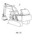
- Fig. 12 illustrates a hydraulic excavator 10, which is a work machine.
- the hydraulic excavator 10 includes a lower structure 11, an upper structure 12, a cab 13, a work equipment 14, and a power system 15 that includes an engine.
- the cab 13, the work equipment 14, and the power system 15 are mounted on the upper structure 12, which is rotatably mounted on the lower structure 11.
- the power system 15 is covered by a top cover 16, side doors 17, and other such components.
- a frame is provided at the machine body.
- the top cover 16 and the side doors 17 are attached to the frame by hinges so as to be capable of opening and closing.
- the side doors 17 or other such components are secured in the closed state to the frame provided at the machine body by means of a latching device 18 (e. g. See Patent Documents 1, 2, and 3).
- a shimmy stopping member 19 for preventing vertical vibration is attached to each side door 17.
- the shimmy stopping members 19 serve to prevent vertical vibration of the side door 17 by respectively catching vertical vibration suppressors 19a, which are attached to the frame at the machine body.
- Examples of conventional means to prevent such vertical vibration include a device for simultaneously stabilizing a portion where two doors overlap each other (e. g. See Patent Document 1) and another device for fitting stoppers provided at the doors with stopper receivers that are provided at the frame at the machine body (e. g. See Patent Document 3).
- Providing shimmy stopping members 19 for preventing vertical vibration as separate members from the latching device 18 presents problems resulting from an increased number of parts, such as not being cost effective due to costs of parts.
- an object of the invention is to reduce the number of parts and also facilitate the layout of the components by integrating with a latching device a shimmy stopping member for preventing vibration of a door panel.
- Claim 1 of the present invention relates to a door unit including a door panel attached to a frame so as to be capable of closing towards and opening away from the frame, an engaging member provided on the frame so as to protrude therefrom, the engaging member provided at such a location as to correspond to a distal end of the door panel, and a latching mechanism portion that is provided on the door and is capable of removably engaging the engaging member to suppress movement of the door panel in a direction in which the door panel is opened or closed, wherein the engaging member and the latching mechanism portion are integrally provided with a first shimmy-stopping engaging portion and a second shimmy-stopping engaging portion that are capable of engaging each other to suppress movement of the door panel in a direction intersecting a direction in which the door panel is opened or closed.
- the engaging member of the door unit according to Claim 1 of the present invention includes a mounting base portion adapted to be fixed to the frame, a plurality of slanted shimmy-stopping surface portions that are formed on the mounting base portion so as to protrude therefrom towards the latching mechanism and collectively serve as the first shimmy-stopping engaging portion, and a stopper portion that protrudes from between the slanted shimmy-stopping surface portions and adapted to be inserted into the latching mechanism.
- the latching mechanism includes a mechanism body portion having a latch groove portion that is formed by cutting away a part of the mechanism body portion and is adapted to engage the stopper portion of the engaging member, and a plurality of shimmy suppressing portions that collectively serve as the second shimmy-stopping engaging portion and are integrally formed at the open end of the latch groove portion of the mechanism body portion and adapted to come into close contact with the plurality of shimmy stopping surface portions of the engaging member so as to prevent vibration of the mechanism body portion.
- the first shimmy-stopping engaging portion and the second shimmy-stopping engaging portion of the door unit according to Claim 1 or Claim 2 of the present invention are both positioned so as to prevent vertical vibration.
- the latching mechanism of the door unit according to Claim 2 or Claim 3 of the present invention is characterized by the latch groove portion of the mechanism body portion having a U-like shape formed by cutting away a part of the mechanism body portion and the shimmy suppressing portions being located at the open end of the latch groove portion so as to collectively form a V-like shape.
- the engaging member of the frame and the latching mechanism on the door panel are not only adapted to engage each other to suppress movement of the door panel in a direction in which the door panel is opened or closed but also integrally provided with a first shimmy-stopping engaging portion and a second shimmy-stopping engaging portion that are capable of suppressing movement of the door panel in a direction intersecting a direction in which the door panel is opened or closed.
- This configuration provides an latching device that serves to suppress movement of the door panel in a direction in which the door panel is opened or closed and is integrally provided with shimmy stopping members for preventing vibration of the door panel in the direction intersecting a direction in which the door panel is opened or closed, thereby reducing the number of parts and also facilitating the layout of the components.
- the engaging member of the frame has a plurality of slanted shimmy-stopping surface portions that are formed on the mounting base portion so as to protrude therefrom towards the latching mechanism, and a stopper portion protruding from between the slanted shimmy-stopping surface portions and adapted to be inserted into the latching mechanism.
- the latching mechanism provided on the door panel has a mechanism body portion having a latch groove portion that is formed by cutting away a part of the mechanism body portion and is adapted to engage the stopper portion of the engaging member, and a plurality of shimmy suppressing portions that collectively serve as the second shimmy-stopping engaging portion and are integrally formed at the open end of the latch groove portion of the mechanism body portion and adapted to come into close contact with the plurality of shimmy stopping surface portions of the engaging member so as to prevent vibration of the mechanism body portion.
- the shimmy stopping members for preventing vibration of the door panel can be compactly integrated with the latching device.
- the first shimmy-stopping engaging portion and the second shimmy-stopping engaging portion are capable of reliably preventing vertical vibration of the door panel.
- the second shimmy-stopping engaging portion is formed in a V-like shape at the open end of the latch groove portion, which is formed in a U-like shape by cutting away a part of the mechanism body portion. Therefore, the guiding function of the second shimmy-stopping engaging portion provides for reliable insertion of the stopper portion of the engaging member into the latch groove portion of the mechanism body portion, and the V-shaped second shimmy-stopping engaging portion is capable of restraining the first shimmy-stopping engaging portion of the engaging member. As a result, vibration of the door panel can reliably be prevented
- Fig. 11 illustrates a hydraulic excavator 10, which is a work machine.
- the hydraulic excavator 10 includes a lower structure 11, an upper structure 12, a cab 13, a work equipment 14, and a power system 15 that includes an engine.
- the cab 13, the work equipment 14, and the power system 15 are mounted on the upper structure 12, which is rotatably mounted on the lower structure 11.
- the power system 15 is covered by a top cover 16, side doors 17, and other such components.
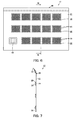
- Figs. 6 to 8 illustrate a door panel 20 of a side door 17.
- the door panel 20 includes an outer panel 21, an inner panel 23, and a foamed material 24.
- the inner panel 23 is formed by press molding a metal plate that is thinner than the outer panel 21 so as to have a bumpy surface with recessed portions and protruding portions. The recessed portions are fixed to the inner surface of the outer panel 21, and a space is formed between the protruding portions and the inner surface of the outer panel 21 and filled by the aforementioned foamed material 24.
- the outer panel 21 has a plurality of honeycomb ventilation hole sections 26, each of which comprises a plurality of regular hexagonal ventilation holes 25 that are formed through the material of the outer panel 21 so as to be arranged in a honeycomb pattern.
- the inner panel 23 has adhered portions 27,28, which are the aforementioned recessed portions adhered to the inner surface of the outer panel 21, and protruding portions 29 raised from the adhered portions 27,28.
- the adhered portions 27 of the inner panel 23 are formed in three laterally extending rows at locations respectively corresponding to the rows of the honeycomb ventilation hole sections 26 of the outer panel 21. Each adhered portion 27 is provided with ventilation openings 30, each of which is larger than each honeycomb ventilation hole section 26 of the outer panel 21.
- a plurality of ventilation openings 30 are formed in the adhered portions 27, which serve as a part of the recessed portions of the inner panel 23.
- Each ventilation opening 30 corresponds to and is slightly larger than each respective honeycomb ventilation hole section 26 of the outer panel 21.
- the rim of the outer panel 21 has a hemmed portion 33 formed by hemming, in other words folding the rim of the outer panel 21 so as to curl over the rim of the inner panel 23 and then pressing down the folded part substantially flat.
- At least the rim of the inner panel 23 is bonded to the outer panel 21 with an adhesive, which bonds as well as seals the outer panel 21 and the inner panel 23 together.
- the adhesive may desirably be a paste-type structural adhesive having both viscous and thermosetting properties.
- An internal reinforcing plate (not illustrated) is disposed near one of the lateral ends of the inner side of the internal panel 23, i.e. the side facing the outer panel 21, and bonded to the outer panel 21. Through hinge mounting openings 34,35 formed in the inner panel 23, hinges 36,37 are welded or otherwise attached to the internal reinforcing plate.
- one of the lateral ends of the door panel 20 of the side door 17 is attached to a frame 41 at the machine body of the hydraulic excavator by means of the hinges 36,37 mentioned above to enable the door panel 20 to open and close freely.
- a latching mechanism 43 of a latching device 42 is provided at the other end of the door panel 20, i.e. the end opposite the end at which the hinges 36,37 are provided.
- a striker 44 that serves as an engaging member for engaging the latching device 42 protrudes from the frame 41 at the machine body so that the door panel 20 when being closed comes into contact with the striker 44.
- the latching mechanism 43 provided on the door panel 20 is capable of engaging with and disengaging from the striker 44.
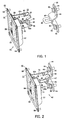
- the striker 44 includes a pair of mounting base portions 45, a pair of slanted shimmy-stopping surface portions 46, and a metal hooking portion 48.
- the mounting base portions 45 constitute the upper part and the lower part of the striker 44 respectively and are adapted to be fixed to the frame 41 provided at the machine body.
- the slanted shimmy-stopping surface portions 46 extend from the mounting base portions 45 respectively so as to protrude in a V-like shape towards the latching mechanism 43 and collectively serve as a first shimmy-stopping engaging portion.
- the metal hooking portion 48 is formed in a U-like shape from a member having a circular cross section and protrudes from a flat end portion 47, which is the portion between the slanted shimmy-stopping surface portions 46.
- the metal hooking portion 48 is adapted to be inserted into the latching mechanism 43 and serves as a stopper portion.
- an elongated hole 49 that is longer in the vertical direction is formed in each mounting base portion 45 of the striker 44.
- the striker 44 is attached to the frame 41 at the machine body with bolts 50 inserted in the elongated holes 49 as illustrated in Fig. 1 . At that time, the vertical position of the striker 44 can be adjusted within the range of the elongated holes 49.
- the latching mechanism 43 has a mounting plate 51 to be attached to the door panel 20.
- a pair of main body plates 52a,52b, which together constitute a mechanism body portion 52, are attached to the mounting plate 51 by means of bolts 53 and nuts 54.
- a portion of each main body plate 52a,52b of the mechanism body portion 52 is cut away to form a U-shaped latch groove portion 55 for engaging the metal hooking portion 48 of the striker 44.
- a pair of shimmy suppressing portions 56 that together form a V-like shape are provided at the open end of each latch groove portion 55 as an integral body therewith. These shimmy suppressing portions 56 collectively serve as a second shimmy-stopping engaging portion.
- Each shimmy suppressing portion 56 is formed by bending outward a part of each main body plate 52a,52b that is in the proximity of the open end of the latch groove portion 55.
- the pair of slanted shimmy-stopping surface portions 46 of the striker 44 are vertically arranged as are the pair of shimmy suppressing portions 56 of each main body plate 52a,52b of the latching mechanism 43 so that the vertically arranged shimmy suppressing portions 56 come into close contact with the vertically arranged slanted shimmy-stopping surface portions 46 of the striker 44 and thereby prevent vertical vibration of the mechanism body portion 52.
- the mounting plate 51 is provided with an operation plate housing portion 57.
- an operation plate 58 for disengagement is pivotally attached to the inside of the operation plate housing portion 57 by a shaft 59.
- the latching mechanism 43 has a latch plate 61 and a locking element 62, both of which are disposed between the pair of main body plates 52a,52b of the mechanism body portion 52.
- the latch plate 61 is disposed at a location close to one end of the pair of main body plates 52a,52b of the mechanism body portion 52 and pivotally supported by a shaft.
- the locking element 62 is disposed at a location close to the opposite end of the pair of main body plates 52a,52b and pivotally supported by a shaft.
- the latch plate 61 has a receiving groove 63 for receiving the metal hooking portion 48 of the striker 44 therein when the metal hooking portion 48 is inserted into the latch groove portion 55 as illustrated in Fig. 2 .
- the latch plate 61 is biased by a spring 64 to such an angle that the receiving groove 63 is open towards the opening of the latch groove portion 55 and stopped by a stopper 65.
- the latch plate 61 pivots and thereby closes off the receiving groove 63.
- the locking element 62 which is constantly pushed against the rim of the latch plate 61 by a spring 66, latches onto the latch plate 61 at a locked state, in other words at an angle to close off the receiving groove 63.
- the locked state by the locking element 62 can be unlocked by a releasing element 67, which functions in conjunction with pivoting of the operation plate 58.
- the unlocking function of the releasing element 67 is kept in check by a locking device 68, which is provided adjacent thereto.
- the mounting plate 51 of the latching mechanism 43 is attached to the door panel 20 by means of rivets 69.
- the door panel 20 of a side door 17, which is attached to one of the lateral ends of the frame 41 at the machine body by means of the hinges 36,37 so as to open and close freely.
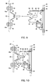
- the latching mechanism 43 of the door panel 20 moves, as illustrated in Fig. 9 , towards the striker 44 attached to the opposite end of the frame 41 with the bolts 50 and nuts 50a so that the metal hooking portion 48 of the striker 44 is inserted into the latch groove portion 55 of the mechanism body portion 52 as illustrated in Fig. 10 .
- the receiving groove 63 of the latch plate 61 is pushed by the metal hooking portion 48 of the striker 44 so that, as illustrated in Fig. 10 , the latch plate 61 pivots and securely engages the metal hooking portion 48 of the striker 44.
- noise reduction is achieved by damping sound from the door panel 20 by means of the foamed material 24 filling the space between the inner panel 23, which can make the entire door panel 20 lighter because of its thinness as illustrated in Fig. 7 , and the outer panel 21, which has a sufficient thickness to ensure the resistance to external impact. Furthermore, noise reduction is achieved also by preventing vibration sound from the door panel 20 by suppressing vertical vibration between the latching mechanism 43 and the striker 44 by means of fitting of the vertically arranged slanted shimmy-stopping surface portions 46 and the vertically arranged shimmy suppressing portions 56.
- the striker 44 and the latching mechanism 43 are integrally provided with a plurality of slanted shimmy-stopping surface portions 46, which serve to suppress movement of the door panel 20 in a vertical direction, i.e. a direction intersecting a direction in which the door panel 20 is opened or closed, as well as a plurality of shimmy suppressing portions 56 to be fitted to the slanted shimmy-stopping surface portions 46.
- This configuration enables the latching device 42 for suppressing opening and closing of the door panel 20 to be integrally provided with shimmy stopping members that serve to prevent vibration of the door panel 20 in a direction intersecting a direction in which the door panel 20 is opened or closed, thereby reducing the number of parts and also facilitating the layout of the components.
- a particular feature of the embodiment lies in that the striker 44 attached to the frame 41 provided at the machine body has a plurality of slanted shimmy-stopping surface portions 46 formed on the mounting base portions 45 so as to protrude therefrom towards the latching mechanism 43, and a metal hooking portion 48 protruding from between the slanted shimmy-stopping surface portions 46 and adapted to be inserted into the latching mechanism 43, and that the latching mechanism 43 provided at the door panel 20 has a mechanism body portion 52 having latch groove portions 55 that are formed therein by cutting away a part of the mechanism body portion 52 and are adapted to engage the metal hooking portion 48 of the striker 44, and a plurality of shimmy suppressing portions 56 that are integrally formed at the open ends of the latch groove portions 55 of the mechanism body portion 52 and adapted to come into close contact with the shimmy stopping surface portions 46 of the striker 44 and thereby preventing vibration of the mechanism body portion 52.
- the vertically arranged plurality of slanted shimmy-stopping surface portions 46 and the vertically arranged plurality of shimmy suppressing portions 56 are capable of reliably preventing vertical vibration of the door panel 20.
- the shimmy suppressing portions 56 are formed in a V-like shape at the open end of each latch groove portion 55, which is formed in a U-like shape by cutting away a part of the mechanism body portion 52. Therefore, the guiding function of the shimmy suppressing portions 56 provides for reliable insertion of the metal hooking portion 48 of the striker 44 into the latch groove portions 55 of the mechanism body portion 52, and the V-shaped shimmy suppressing portions 56 are capable of restraining the slanted shimmy-stopping surface portions 46 of the striker 44. As a result, vibration of the door panel 20 can reliably be prevented.
- the slanted shimmy-stopping surface portions 46 of the striker 44 serve as the first shimmy-stopping engaging portion
- the shimmy suppressing portions 56 of the latching mechanism 43 serve as the second shimmy-stopping engaging portion according to the embodiments illustrated in the drawings
- their positional relationship may be reversed.
- the first shimmy-stopping engaging portion may comprise the shimmy suppressing portions 56 of the latching mechanism 43
- the second shimmy-stopping engaging portion comprise the slanted shimmy-stopping surface portions 46 of the striker 44.
- the main body plates 52a,52b of the latching mechanism 43 and the mounting base portions 45 of the striker 44 may be processed so that the upper and lower portions of the main body plates 52a,52b are formed into a first shimmy-stopping engaging portion and that the upper end and the lower end of the mounting base portions 45 project towards the main body plates 52a,52b and serve as shimmy suppressing portions.
- the present invention is applicable to a side door, a rear door, etc. of a work machine, such as a hydraulic excavator.
Landscapes
- Engineering & Computer Science (AREA)
- Mining & Mineral Resources (AREA)
- Civil Engineering (AREA)
- General Engineering & Computer Science (AREA)
- Structural Engineering (AREA)
- Mechanical Engineering (AREA)
- Lock And Its Accessories (AREA)
- Component Parts Of Construction Machinery (AREA)
- Superstructure Of Vehicle (AREA)
Applications Claiming Priority (2)
| Application Number | Priority Date | Filing Date | Title |
|---|---|---|---|
| JP2007280255A JP5004231B2 (ja) | 2007-10-29 | 2007-10-29 | 作業機械用ドア装置 |
| PCT/JP2008/062166 WO2009057351A1 (fr) | 2007-10-29 | 2008-07-04 | Dispositif de porte |
Publications (3)
| Publication Number | Publication Date |
|---|---|
| EP2204519A1 true EP2204519A1 (fr) | 2010-07-07 |
| EP2204519A4 EP2204519A4 (fr) | 2011-06-08 |
| EP2204519B1 EP2204519B1 (fr) | 2013-10-16 |
Family
ID=40590754
Family Applications (1)
| Application Number | Title | Priority Date | Filing Date |
|---|---|---|---|
| EP08777881.7A Active EP2204519B1 (fr) | 2007-10-29 | 2008-07-04 | Dispositif de porte |
Country Status (5)
| Country | Link |
|---|---|
| US (1) | US8439409B2 (fr) |
| EP (1) | EP2204519B1 (fr) |
| JP (1) | JP5004231B2 (fr) |
| CN (1) | CN101542064A (fr) |
| WO (1) | WO2009057351A1 (fr) |
Families Citing this family (17)
| Publication number | Priority date | Publication date | Assignee | Title |
|---|---|---|---|---|
| CN101967922A (zh) * | 2010-06-29 | 2011-02-09 | 江苏奔宇车身制造有限公司 | 一种可调式门锁扣装配结构 |
| US8770635B2 (en) * | 2011-04-20 | 2014-07-08 | Trimark Corporation | Grapple style compression latch |
| JP5819760B2 (ja) * | 2012-03-29 | 2015-11-24 | ヤンマー株式会社 | 旋回作業車のボンネット開閉構造 |
| US8938913B2 (en) * | 2012-06-05 | 2015-01-27 | Siemens Industry, Inc. | Self-locating door interlock apparatus and enclosures, assemblies, and methods including same |
| CN104703867A (zh) * | 2012-10-09 | 2015-06-10 | 沃尔沃建造设备有限公司 | 用于施工机械发动机室的发动机罩的锁定装置 |
| JP6048125B2 (ja) * | 2012-12-21 | 2016-12-21 | アイシン精機株式会社 | 車両ドアの固定装置 |
| US9175505B2 (en) * | 2013-02-06 | 2015-11-03 | Honda Motor Co., Ltd. | Door handle assemblies and vehicles having same |
| CN108139783B (zh) * | 2015-11-06 | 2021-07-20 | 松下知识产权经营株式会社 | 电子设备及闩锁机构 |
| CN110114542B (zh) * | 2016-10-21 | 2021-08-10 | 索斯科公司 | 箱子闩锁 |
| KR102395304B1 (ko) * | 2017-11-28 | 2022-05-09 | 현대자동차주식회사 | 차량 테일게이트용 스토퍼장치 |
| JP6852109B2 (ja) * | 2019-04-10 | 2021-03-31 | 株式会社豊田自動織機 | ストライカ取付構造 |
| CN110230442A (zh) * | 2019-05-08 | 2019-09-13 | 南昌汇达知识产权有限公司 | 一种汽车车门紧急手动开关装置 |
| JP7078209B2 (ja) * | 2019-08-21 | 2022-05-31 | 三井金属アクト株式会社 | 自動車用ドアのストライカ |
| KR102141719B1 (ko) * | 2020-03-31 | 2020-08-05 | 김동우 | 화재 및 재난 피난장치 |
| GB2605411B (en) * | 2021-03-31 | 2024-07-17 | Jaguar Land Rover Ltd | Deformable striker apparatus for a vehicle split tailgate system |
| DE102022108376A1 (de) * | 2022-04-07 | 2023-10-12 | Kiekert Aktiengesellschaft | Schlosshalter für eine Kraftfahrzeug-Schließeinrichtung |
| US20260043279A1 (en) * | 2024-08-08 | 2026-02-12 | Bauer Products, Inc, | Compartment door latch |
Family Cites Families (48)
| Publication number | Priority date | Publication date | Assignee | Title |
|---|---|---|---|---|
| US417845A (en) * | 1889-12-24 | Lock-strike | ||
| US1690408A (en) * | 1926-10-25 | 1928-11-06 | Champion Hardware Company | Hasp |
| US1888829A (en) * | 1929-12-16 | 1932-11-22 | Bassick Co | Self-adjusting antirattle dovetail for doors |
| US1903365A (en) * | 1931-07-08 | 1933-04-04 | Ternstedt Mfg Co | Comrination dovetail and door bumper |
| US1948640A (en) * | 1932-06-02 | 1934-02-27 | Andrews Isaac | Antirattle device |
| US3433518A (en) * | 1967-03-16 | 1969-03-18 | Lawrence Brothers | Latch assembly |
| US3549185A (en) * | 1968-06-10 | 1970-12-22 | Porter Co Inc H K | Door fastening apparatus |
| US3734551A (en) * | 1971-06-28 | 1973-05-22 | Latch Plastics Inc | Closure-fastener for cabinets or the like |
| JPS556920Y2 (fr) * | 1975-11-05 | 1980-02-16 | ||
| JPS5263817A (en) | 1975-11-21 | 1977-05-26 | Fuji Raito Kougiyou Kk | Mold forming for casting |
| DE2725345C2 (de) | 1977-06-04 | 1985-05-23 | Daimler-Benz Ag, 7000 Stuttgart | Aus einem Stahlblechzuschnitt gebogener Schließkloben für einen Kraftfahr-Türverschluß |
| JPS556920A (en) | 1978-06-30 | 1980-01-18 | Iwatsu Electric Co Ltd | Automatic answering telephone set |
| US4305611A (en) * | 1978-09-01 | 1981-12-15 | Pti-Dolco | Adjustable gate latch |
| US4466645A (en) * | 1982-03-22 | 1984-08-21 | Ohi Seisakusho Co., Ltd. | Automobile door latch striker |
| US4505501A (en) * | 1983-08-30 | 1985-03-19 | The Knapheide Mfg. Co. | Latching device |
| CA1294297C (fr) * | 1986-12-17 | 1992-01-14 | Wolfgang Thau | Gache, logement de pene et mecanisme de verrouillage pour portiere de vehicule |
| US4896906A (en) * | 1987-05-27 | 1990-01-30 | The Eastern Company | Vehicle door lock system |
| US5069491A (en) * | 1987-05-27 | 1991-12-03 | The Eastern Company | Vehicle door lock system |
| IT212714Z2 (it) * | 1987-10-30 | 1989-08-28 | Fiat Auto Spa | Serratura in particolare per un portellone posteriore di un veicolo con bloccaggio trasversale a recupero automatico dei giochi |
| CA1320238C (fr) * | 1988-03-14 | 1993-07-13 | Shinjiro Yamada | Verrou de portiere de vehicule |
| US5358292A (en) * | 1992-03-12 | 1994-10-25 | Wiebe Peter C Van | Gate latch |
| DE4212327A1 (de) * | 1992-04-13 | 1993-10-14 | Bocklenberg & Motte Bomoro | Kraftfahrzeug-Türschloß |
| JPH07293105A (ja) * | 1994-04-27 | 1995-11-07 | Araco Corp | 車両用ドアのドアストッパ構造 |
| US5529356A (en) * | 1994-05-25 | 1996-06-25 | Atoma International Inc. | Vehicle door striker with improved end portion |
| US5655801A (en) * | 1995-09-21 | 1997-08-12 | Casey; Michael | Gate latch |
| US5618066A (en) | 1995-11-13 | 1997-04-08 | Fu-Hsiang; Chen | Automatic latch device |
| GB2316439B (en) * | 1996-08-23 | 1999-08-11 | Mitsui Mining & Smelting Co | Latch device for vehicle back door |
| JP3531088B2 (ja) * | 1996-09-27 | 2004-05-24 | 株式会社大井製作所 | 自動車用ドアの電動式閉扉装置 |
| US5707092A (en) * | 1996-11-26 | 1998-01-13 | General Motors Corporation | Self-aligning loop striker |
| DE19654380A1 (de) * | 1996-12-24 | 1998-06-25 | Mannesmann Vdo Ag | Schließeinrichtung, insbesondere für eine Heckklappe eines Kraftfahrzeuges |
| US6095576A (en) * | 1998-07-20 | 2000-08-01 | Atf Inc. | Door latch striker |
| US6347819B1 (en) * | 1999-09-15 | 2002-02-19 | Shawn Plaxco | Safety latching mechanism |
| JP3669568B2 (ja) | 2000-03-22 | 2005-07-06 | 日立建機株式会社 | 建設機械のドア用振れ止め装置 |
| DE10018560A1 (de) * | 2000-04-14 | 2001-10-31 | Daimler Chrysler Ag | Fahrzeugschloss, insbesondere für eine Heckklappentür |
| DE10062458B4 (de) * | 2000-12-14 | 2004-06-17 | Whirlpool Corp., Benton Harbor | Schließvorrichtung für eine Waschmaschine oder einen Waschtrockner |
| US7097219B2 (en) * | 2002-05-03 | 2006-08-29 | Anchor Tool & Die Company | Encapsulated striker assembly |
| GB0223617D0 (en) * | 2002-10-11 | 2002-11-20 | Arvinmeritor Light Vehicle Sys | Latch assembly and striker |
| GB0223618D0 (en) * | 2002-10-11 | 2002-11-20 | Arvinmeritor Light Vehicle Sys | Latch assembly, latch and striker |
| US6932192B2 (en) * | 2002-10-25 | 2005-08-23 | Chem-Tainer Industries, Inc. | Boat stairs bracket |
| US6883842B2 (en) * | 2002-12-19 | 2005-04-26 | Anchor Tool & Die Company | Latch strikers with mechanically locked components |
| US20070001468A1 (en) * | 2004-03-29 | 2007-01-04 | Burton John E | Bent wire door striker |
| KR100552770B1 (ko) * | 2004-05-14 | 2006-02-20 | 현대자동차주식회사 | 차량용 스트라이커 어셈블리 |
| JP2007137183A (ja) | 2005-11-16 | 2007-06-07 | Shin Caterpillar Mitsubishi Ltd | 作業機械のエンジンフード閉じ用止め具構造 |
| JP4907981B2 (ja) | 2005-12-26 | 2012-04-04 | 日立建機株式会社 | 開閉扉固定装置 |
| US20070241570A1 (en) * | 2006-04-03 | 2007-10-18 | Paskonis Almantas K | Latch and latch striker interface improvements |
| CN101668916B (zh) * | 2007-02-28 | 2017-07-28 | 马格纳·克劳祖雷斯有限公司 | 模块式锁具 |
| JP5012101B2 (ja) * | 2007-03-09 | 2012-08-29 | アイシン精機株式会社 | 車両用ストライカ装置 |
| US7938458B1 (en) * | 2007-09-21 | 2011-05-10 | Trimark Corporation | Alignment assembly for door latch and striker bolt |
-
2007
- 2007-10-29 JP JP2007280255A patent/JP5004231B2/ja active Active
-
2008
- 2008-07-04 CN CNA2008800003322A patent/CN101542064A/zh active Pending
- 2008-07-04 EP EP08777881.7A patent/EP2204519B1/fr active Active
- 2008-07-04 WO PCT/JP2008/062166 patent/WO2009057351A1/fr not_active Ceased
- 2008-07-04 US US12/374,952 patent/US8439409B2/en not_active Expired - Fee Related
Also Published As
| Publication number | Publication date |
|---|---|
| EP2204519B1 (fr) | 2013-10-16 |
| CN101542064A (zh) | 2009-09-23 |
| JP5004231B2 (ja) | 2012-08-22 |
| EP2204519A4 (fr) | 2011-06-08 |
| US8439409B2 (en) | 2013-05-14 |
| US20100223855A1 (en) | 2010-09-09 |
| WO2009057351A1 (fr) | 2009-05-07 |
| JP2009108539A (ja) | 2009-05-21 |
Similar Documents
| Publication | Publication Date | Title |
|---|---|---|
| EP2204519A1 (fr) | Dispositif de porte | |
| JP4914763B2 (ja) | ハンドル装置 | |
| EP2562339B1 (fr) | Appareil de fixation de porte de véhicule et sa cale fixe | |
| US10166847B2 (en) | Vehicle side portion structure | |
| EP1842705B1 (fr) | Module de support pour portes de véhicule et procédé de montage de tel module | |
| CN104417327B (zh) | 车门外把手 | |
| KR20130131474A (ko) | 차량용 러기지 도어 구조 | |
| EP1630327A1 (fr) | Poignée de porte pour véhicule | |
| JP4423612B2 (ja) | ドアガードバーの取付構造 | |
| EP1980690A2 (fr) | Porte de capot moteur comportant une poignée de porte réglable | |
| EP1764465A1 (fr) | Mécanisme de verrouillage de couvercle | |
| US7416212B2 (en) | Absorption structure of a container device for an instrument panel for absorbing energy applied from knees of an occupant | |
| JP5131749B2 (ja) | 作業機械用ドア装置 | |
| JP5013471B2 (ja) | ドア装置 | |
| CN103129629B (zh) | 用于安装行李舱盖的车辆结构 | |
| JP4396991B2 (ja) | キャビネット | |
| JP4076972B2 (ja) | ドアアウタハンドル構造 | |
| WO2011101953A1 (fr) | Mécanisme de verrouillage de couvercle | |
| JP4631592B2 (ja) | 穴閉鎖プラグ | |
| KR100829284B1 (ko) | 자동차용 도어 힌지 구조 | |
| JP2009150059A (ja) | ドア装置 | |
| KR200371342Y1 (ko) | 중장비의 전면유리창용 록킹장치 | |
| JP2011111810A (ja) | ドアハンドル構造 | |
| EP1803877A2 (fr) | Structure de poignée de porte nécessitant un espace réduit pour la mise en place d'un mécanisme de relâchement d'un loquet de porte | |
| US10538943B2 (en) | Door latch apparatus for door for vehicle |
Legal Events
| Date | Code | Title | Description |
|---|---|---|---|
| PUAI | Public reference made under article 153(3) epc to a published international application that has entered the european phase |
Free format text: ORIGINAL CODE: 0009012 |
|
| 17P | Request for examination filed |
Effective date: 20100528 |
|
| AK | Designated contracting states |
Kind code of ref document: A1 Designated state(s): AT BE BG CH CY CZ DE DK EE ES FI FR GB GR HR HU IE IS IT LI LT LU LV MC MT NL NO PL PT RO SE SI SK TR |
|
| AX | Request for extension of the european patent |
Extension state: AL BA MK RS |
|
| RAP1 | Party data changed (applicant data changed or rights of an application transferred) |
Owner name: CATERPILLAR SARL |
|
| DAX | Request for extension of the european patent (deleted) | ||
| A4 | Supplementary search report drawn up and despatched |
Effective date: 20110510 |
|
| 17Q | First examination report despatched |
Effective date: 20110527 |
|
| GRAP | Despatch of communication of intention to grant a patent |
Free format text: ORIGINAL CODE: EPIDOSNIGR1 |
|
| INTG | Intention to grant announced |
Effective date: 20130514 |
|
| GRAS | Grant fee paid |
Free format text: ORIGINAL CODE: EPIDOSNIGR3 |
|
| GRAA | (expected) grant |
Free format text: ORIGINAL CODE: 0009210 |
|
| AK | Designated contracting states |
Kind code of ref document: B1 Designated state(s): AT BE BG CH CY CZ DE DK EE ES FI FR GB GR HR HU IE IS IT LI LT LU LV MC MT NL NO PL PT RO SE SI SK TR |
|
| REG | Reference to a national code |
Ref country code: GB Ref legal event code: FG4D |
|
| REG | Reference to a national code |
Ref country code: CH Ref legal event code: EP |
|
| REG | Reference to a national code |
Ref country code: IE Ref legal event code: FG4D |
|
| REG | Reference to a national code |
Ref country code: AT Ref legal event code: REF Ref document number: 636608 Country of ref document: AT Kind code of ref document: T Effective date: 20131115 |
|
| REG | Reference to a national code |
Ref country code: DE Ref legal event code: R082 Ref document number: 602008028158 Country of ref document: DE Representative=s name: DTS MUENCHEN PATENT- UND RECHTSANWAELTE, DE Ref country code: DE Ref legal event code: R082 Ref document number: 602008028158 Country of ref document: DE Representative=s name: DTS PATENT- UND RECHTSANWAELTE SCHNEKENBUEHL U, DE |
|
| REG | Reference to a national code |
Ref country code: DE Ref legal event code: R096 Ref document number: 602008028158 Country of ref document: DE Effective date: 20131212 |
|
| REG | Reference to a national code |
Ref country code: NL Ref legal event code: VDEP Effective date: 20131016 |
|
| REG | Reference to a national code |
Ref country code: AT Ref legal event code: MK05 Ref document number: 636608 Country of ref document: AT Kind code of ref document: T Effective date: 20131016 |
|
| REG | Reference to a national code |
Ref country code: LT Ref legal event code: MG4D |
|
| PG25 | Lapsed in a contracting state [announced via postgrant information from national office to epo] |
Ref country code: NO Free format text: LAPSE BECAUSE OF FAILURE TO SUBMIT A TRANSLATION OF THE DESCRIPTION OR TO PAY THE FEE WITHIN THE PRESCRIBED TIME-LIMIT Effective date: 20140116 Ref country code: IS Free format text: LAPSE BECAUSE OF FAILURE TO SUBMIT A TRANSLATION OF THE DESCRIPTION OR TO PAY THE FEE WITHIN THE PRESCRIBED TIME-LIMIT Effective date: 20140216 Ref country code: LT Free format text: LAPSE BECAUSE OF FAILURE TO SUBMIT A TRANSLATION OF THE DESCRIPTION OR TO PAY THE FEE WITHIN THE PRESCRIBED TIME-LIMIT Effective date: 20131016 Ref country code: BE Free format text: LAPSE BECAUSE OF FAILURE TO SUBMIT A TRANSLATION OF THE DESCRIPTION OR TO PAY THE FEE WITHIN THE PRESCRIBED TIME-LIMIT Effective date: 20131016 Ref country code: NL Free format text: LAPSE BECAUSE OF FAILURE TO SUBMIT A TRANSLATION OF THE DESCRIPTION OR TO PAY THE FEE WITHIN THE PRESCRIBED TIME-LIMIT Effective date: 20131016 Ref country code: FI Free format text: LAPSE BECAUSE OF FAILURE TO SUBMIT A TRANSLATION OF THE DESCRIPTION OR TO PAY THE FEE WITHIN THE PRESCRIBED TIME-LIMIT Effective date: 20131016 Ref country code: SE Free format text: LAPSE BECAUSE OF FAILURE TO SUBMIT A TRANSLATION OF THE DESCRIPTION OR TO PAY THE FEE WITHIN THE PRESCRIBED TIME-LIMIT Effective date: 20131016 Ref country code: HR Free format text: LAPSE BECAUSE OF FAILURE TO SUBMIT A TRANSLATION OF THE DESCRIPTION OR TO PAY THE FEE WITHIN THE PRESCRIBED TIME-LIMIT Effective date: 20131016 |
|
| PG25 | Lapsed in a contracting state [announced via postgrant information from national office to epo] |
Ref country code: LV Free format text: LAPSE BECAUSE OF FAILURE TO SUBMIT A TRANSLATION OF THE DESCRIPTION OR TO PAY THE FEE WITHIN THE PRESCRIBED TIME-LIMIT Effective date: 20131016 Ref country code: AT Free format text: LAPSE BECAUSE OF FAILURE TO SUBMIT A TRANSLATION OF THE DESCRIPTION OR TO PAY THE FEE WITHIN THE PRESCRIBED TIME-LIMIT Effective date: 20131016 Ref country code: CY Free format text: LAPSE BECAUSE OF FAILURE TO SUBMIT A TRANSLATION OF THE DESCRIPTION OR TO PAY THE FEE WITHIN THE PRESCRIBED TIME-LIMIT Effective date: 20131016 Ref country code: ES Free format text: LAPSE BECAUSE OF FAILURE TO SUBMIT A TRANSLATION OF THE DESCRIPTION OR TO PAY THE FEE WITHIN THE PRESCRIBED TIME-LIMIT Effective date: 20131016 |
|
| PG25 | Lapsed in a contracting state [announced via postgrant information from national office to epo] |
Ref country code: PT Free format text: LAPSE BECAUSE OF FAILURE TO SUBMIT A TRANSLATION OF THE DESCRIPTION OR TO PAY THE FEE WITHIN THE PRESCRIBED TIME-LIMIT Effective date: 20140217 |
|
| REG | Reference to a national code |
Ref country code: DE Ref legal event code: R097 Ref document number: 602008028158 Country of ref document: DE |
|
| PG25 | Lapsed in a contracting state [announced via postgrant information from national office to epo] |
Ref country code: EE Free format text: LAPSE BECAUSE OF FAILURE TO SUBMIT A TRANSLATION OF THE DESCRIPTION OR TO PAY THE FEE WITHIN THE PRESCRIBED TIME-LIMIT Effective date: 20131016 |
|
| PLBE | No opposition filed within time limit |
Free format text: ORIGINAL CODE: 0009261 |
|
| STAA | Information on the status of an ep patent application or granted ep patent |
Free format text: STATUS: NO OPPOSITION FILED WITHIN TIME LIMIT |
|
| PG25 | Lapsed in a contracting state [announced via postgrant information from national office to epo] |
Ref country code: RO Free format text: LAPSE BECAUSE OF FAILURE TO SUBMIT A TRANSLATION OF THE DESCRIPTION OR TO PAY THE FEE WITHIN THE PRESCRIBED TIME-LIMIT Effective date: 20131016 Ref country code: IT Free format text: LAPSE BECAUSE OF FAILURE TO SUBMIT A TRANSLATION OF THE DESCRIPTION OR TO PAY THE FEE WITHIN THE PRESCRIBED TIME-LIMIT Effective date: 20131016 Ref country code: PL Free format text: LAPSE BECAUSE OF FAILURE TO SUBMIT A TRANSLATION OF THE DESCRIPTION OR TO PAY THE FEE WITHIN THE PRESCRIBED TIME-LIMIT Effective date: 20131016 Ref country code: CZ Free format text: LAPSE BECAUSE OF FAILURE TO SUBMIT A TRANSLATION OF THE DESCRIPTION OR TO PAY THE FEE WITHIN THE PRESCRIBED TIME-LIMIT Effective date: 20131016 Ref country code: SK Free format text: LAPSE BECAUSE OF FAILURE TO SUBMIT A TRANSLATION OF THE DESCRIPTION OR TO PAY THE FEE WITHIN THE PRESCRIBED TIME-LIMIT Effective date: 20131016 |
|
| 26N | No opposition filed |
Effective date: 20140717 |
|
| PG25 | Lapsed in a contracting state [announced via postgrant information from national office to epo] |
Ref country code: DK Free format text: LAPSE BECAUSE OF FAILURE TO SUBMIT A TRANSLATION OF THE DESCRIPTION OR TO PAY THE FEE WITHIN THE PRESCRIBED TIME-LIMIT Effective date: 20131016 |
|
| REG | Reference to a national code |
Ref country code: DE Ref legal event code: R097 Ref document number: 602008028158 Country of ref document: DE Effective date: 20140717 |
|
| PG25 | Lapsed in a contracting state [announced via postgrant information from national office to epo] |
Ref country code: SI Free format text: LAPSE BECAUSE OF FAILURE TO SUBMIT A TRANSLATION OF THE DESCRIPTION OR TO PAY THE FEE WITHIN THE PRESCRIBED TIME-LIMIT Effective date: 20131016 Ref country code: LU Free format text: LAPSE BECAUSE OF FAILURE TO SUBMIT A TRANSLATION OF THE DESCRIPTION OR TO PAY THE FEE WITHIN THE PRESCRIBED TIME-LIMIT Effective date: 20140704 |
|
| REG | Reference to a national code |
Ref country code: CH Ref legal event code: PL |
|
| GBPC | Gb: european patent ceased through non-payment of renewal fee |
Effective date: 20140704 |
|
| REG | Reference to a national code |
Ref country code: IE Ref legal event code: MM4A |
|
| REG | Reference to a national code |
Ref country code: FR Ref legal event code: ST Effective date: 20150331 |
|
| PG25 | Lapsed in a contracting state [announced via postgrant information from national office to epo] |
Ref country code: CH Free format text: LAPSE BECAUSE OF NON-PAYMENT OF DUE FEES Effective date: 20140731 Ref country code: LI Free format text: LAPSE BECAUSE OF NON-PAYMENT OF DUE FEES Effective date: 20140731 |
|
| PG25 | Lapsed in a contracting state [announced via postgrant information from national office to epo] |
Ref country code: GB Free format text: LAPSE BECAUSE OF NON-PAYMENT OF DUE FEES Effective date: 20140704 Ref country code: FR Free format text: LAPSE BECAUSE OF NON-PAYMENT OF DUE FEES Effective date: 20140731 |
|
| PG25 | Lapsed in a contracting state [announced via postgrant information from national office to epo] |
Ref country code: IE Free format text: LAPSE BECAUSE OF NON-PAYMENT OF DUE FEES Effective date: 20140704 |
|
| PG25 | Lapsed in a contracting state [announced via postgrant information from national office to epo] |
Ref country code: MC Free format text: LAPSE BECAUSE OF FAILURE TO SUBMIT A TRANSLATION OF THE DESCRIPTION OR TO PAY THE FEE WITHIN THE PRESCRIBED TIME-LIMIT Effective date: 20131016 |
|
| PG25 | Lapsed in a contracting state [announced via postgrant information from national office to epo] |
Ref country code: BG Free format text: LAPSE BECAUSE OF FAILURE TO SUBMIT A TRANSLATION OF THE DESCRIPTION OR TO PAY THE FEE WITHIN THE PRESCRIBED TIME-LIMIT Effective date: 20131016 |
|
| PG25 | Lapsed in a contracting state [announced via postgrant information from national office to epo] |
Ref country code: GR Free format text: LAPSE BECAUSE OF FAILURE TO SUBMIT A TRANSLATION OF THE DESCRIPTION OR TO PAY THE FEE WITHIN THE PRESCRIBED TIME-LIMIT Effective date: 20140117 Ref country code: MT Free format text: LAPSE BECAUSE OF FAILURE TO SUBMIT A TRANSLATION OF THE DESCRIPTION OR TO PAY THE FEE WITHIN THE PRESCRIBED TIME-LIMIT Effective date: 20131016 |
|
| PG25 | Lapsed in a contracting state [announced via postgrant information from national office to epo] |
Ref country code: HU Free format text: LAPSE BECAUSE OF FAILURE TO SUBMIT A TRANSLATION OF THE DESCRIPTION OR TO PAY THE FEE WITHIN THE PRESCRIBED TIME-LIMIT; INVALID AB INITIO Effective date: 20080704 Ref country code: TR Free format text: LAPSE BECAUSE OF FAILURE TO SUBMIT A TRANSLATION OF THE DESCRIPTION OR TO PAY THE FEE WITHIN THE PRESCRIBED TIME-LIMIT Effective date: 20131016 |
|
| P01 | Opt-out of the competence of the unified patent court (upc) registered |
Effective date: 20230517 |
|
| PGFP | Annual fee paid to national office [announced via postgrant information from national office to epo] |
Ref country code: DE Payment date: 20250620 Year of fee payment: 18 |