EP2204521B1 - Système de surveillance de verrouillage électromagnétique - Google Patents
Système de surveillance de verrouillage électromagnétique Download PDFInfo
- Publication number
- EP2204521B1 EP2204521B1 EP09010307.8A EP09010307A EP2204521B1 EP 2204521 B1 EP2204521 B1 EP 2204521B1 EP 09010307 A EP09010307 A EP 09010307A EP 2204521 B1 EP2204521 B1 EP 2204521B1
- Authority
- EP
- European Patent Office
- Prior art keywords
- electromagnet
- hall effect
- effect sensors
- accordance
- electromagnetic lock
- Prior art date
- Legal status (The legal status is an assumption and is not a legal conclusion. Google has not performed a legal analysis and makes no representation as to the accuracy of the status listed.)
- Active
Links
Images



Classifications
-
- E—FIXED CONSTRUCTIONS
- E05—LOCKS; KEYS; WINDOW OR DOOR FITTINGS; SAFES
- E05C—BOLTS OR FASTENING DEVICES FOR WINGS, SPECIALLY FOR DOORS OR WINDOWS
- E05C19/00—Other devices specially designed for securing wings, e.g. with suction cups
- E05C19/16—Devices holding the wing by magnetic or electromagnetic attraction
- E05C19/166—Devices holding the wing by magnetic or electromagnetic attraction electromagnetic
-
- G—PHYSICS
- G01—MEASURING; TESTING
- G01R—MEASURING ELECTRIC VARIABLES; MEASURING MAGNETIC VARIABLES
- G01R33/00—Arrangements or instruments for measuring magnetic variables
- G01R33/02—Measuring direction or magnitude of magnetic fields or magnetic flux
- G01R33/06—Measuring direction or magnitude of magnetic fields or magnetic flux using galvano-magnetic devices
- G01R33/07—Hall effect devices
- G01R33/072—Constructional adaptation of the sensor to specific applications
-
- Y—GENERAL TAGGING OF NEW TECHNOLOGICAL DEVELOPMENTS; GENERAL TAGGING OF CROSS-SECTIONAL TECHNOLOGIES SPANNING OVER SEVERAL SECTIONS OF THE IPC; TECHNICAL SUBJECTS COVERED BY FORMER USPC CROSS-REFERENCE ART COLLECTIONS [XRACs] AND DIGESTS
- Y10—TECHNICAL SUBJECTS COVERED BY FORMER USPC
- Y10T—TECHNICAL SUBJECTS COVERED BY FORMER US CLASSIFICATION
- Y10T70/00—Locks
- Y10T70/70—Operating mechanism
- Y10T70/7051—Using a powered device [e.g., motor]
- Y10T70/7062—Electrical type [e.g., solenoid]
Definitions
- the present invention relates to electromagnetic locks; more particularly, to an electromagnet having a system for monitoring the lock status of an electromagnetic lock employing a plurality of hall sensors; and an electromagnetic lock system comprising such an electromagnet.
- Electromagnetic locks for securing doors or gates are well known in the prior art.
- a magnetically-susceptible plate is mounted on a door, and an electromagnet is mounted on a door jamb or gate post.
- the electromagnet When the electromagnet is energized, is in contact with the plate, and the door is closed, the plate becomes an armature for the electromagnet.
- Magnetic flux passes between the electromagnet and the armature, attracting the armature to the electromagnet and thus providing a mechanism for locking the door to the jamb.
- the magnetic loop is complete, by contact of the armature with the electromagnet, the magnetic flux density is at a maximum.
- a device that can sense the strength of the magnetic field can be configured as an alarm mechanism for a door that is not fully or properly secured by an electromagnetic lock or for a door that is being forced open by an attempt to forcibly sepatate the armature and electromagnet.
- a significant problem with such a prior art system is that only the magnetic field immediately adjacent the Hall Effect device is actually monitored.
- an armature plate may be offset laterally by up to several inches from the electromagnet, thus significantly reducing the total holding force of the lock but still having the same magnetic strength near the Hall Effect device.
- use of a single Hall Effect device may lead to monitoring only half of the actual magnetic field available, as there are two overlapping magnetic fields in operation with a typical E-shaped magnetic core used in many prior art electromagnetic locks.
- US-A-6,271,751 A describes a magnetic lock and status detection system and method therefore. It describes mounting Hall-effect devices or magnetic reed switches around the periphery of the magnetic core of the magnetic lock to counteract defeating the monitoring system.
- US 4 287 512 A discloses an electromagnet according to the preamble of claim 1 and relates to a magnetic locking method and apparatus inter alia comprising an electromagnetic locking assembly having an electromagnet core comprised of three core elements formed in an E shape.
- the assembly has two Hall Effect sensors, one embedded in the outer leg of the E shaped core and the other embedded in the opposite outer leg of the E shaped core.
- EP 1867 820 A1 relates to a closing device that can be monitored and inter alia discloses an electromagnetic locking device having an electromagnet core comprised of three core elements formed in an E shape.
- the device has a Reed switch disposed in the center leg of the E shaped core and a Hall Effect sensor disposed within one of the outer legs of the core.
- an electromagnet having a system for monitoring the locked status of an electromagnetic lock and an electromagnetic lock system as set forth in claims 1 and 6, respectively, is provided. Further embodiments of the invention are claimed in the respective dependent claims.
- an electromagnet having a lock monitoring system in accordance with the present invention monitors the strength of a magnetic field in an electromechanical lock which is created when a steel armature plate is properly closed against the magnet.
- the system utilizes a plurality of Hall Effect devices, preferably two, positioned in such a way that both ends of the electromagnet and both magnetic fields are monitored, and that the resulting monitoring effectively covers the complete contact surface between the electromagnet and the armature plate.
- the Hall Effect devices are disposed at the point of maximum flux density within the center element of an E-shaped electromagnetic core, at opposite ends of the core and are preferably connected in series with a relay. If the magnetic flux falls below a preset limit, the relay drops out, triggering an alarm which may be sonic, electronic, and/or visual, as is known in the prior art. Lock misalignments as small as 0.25 inch may be detected.
- the Hall effect comes about due to the nature of the current in a conductor.
- Current I consists of the movement of many small charge-carrying "particles" (typically, but not necessarily, electrons).
- Moving charges experience a force, called the Lorentz Force, when a magnetic field B is present that is not parallel to their motion. When such a magnetic field is absent, the charges follow an approximately straight 'line of sight' path 10.
- a perpendicular magnetic field B when a perpendicular magnetic field B is applied, their path is curved 12 so that moving charges accumulate on one face 14 of the material. This leaves equal and opposite charges exposed on the other face 16, where there is a scarcity of mobile charges.
- V H ⁇ IB / d ne , where I is the current across the plate length, B is the magnetic flux density, d is the depth of the plate, e is the electron charge, and n is the charge carrier density of the carrier electrons.
- the Hall effect is very useful as a means to measure either the carrier density or the magnetic field.
- This sensitivity to the intensity of the magnetic field is applied in the present invention to monitor whether a magnetic strike plate is properly aligned to an electromagnetic lock in the X, Y, and Z directions.
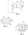
- Lock 110 comprises an electromagnet 116, which preferably is mounted on door jamb 114, and an armature strike plate 118, which preferably is mounted on door 112.
- This arrangement is preferable because it is easier to provide electric power to an electromagnet mounted on a stationary jamb, but of course the invention is equally functional when the electromagnet is mounted on the door (not shown) and the armature strike plate is mounted on the jamb (not shown).
- a single Hall Effect sensor as employed in the prior art may not reliably indicate an unacceptable condition of non-alignment. Therefore, in accordance with the present invention a plurality of Hall Effect devices are spaced apart within the magnetic field such that an alarm condition is established when any one of the Hall effect devices detects a magnetic field strength below a predetermined alarm level.
- the Hall Effect sensors preferably two, 120a,120b, preferably are disposed as shown near the ends of electromagnet 116 and centered in the middle element 116b of the "E-shaped" magnetic core. At that point, the magnetic flux 122 is most concentrated and therefore provides the sharpest indication of flux reduction if the armature plate should be misaligned on the surface of the core. Dimension 124 is chosen to place the Hall Effect devices 120a,120b at the point of maximum flux concentration for the core.
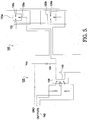
- Hall Effect devices 120a,120b are connected to a control apparatus 126 wherein devices 120a,120b are connected in series with a relay as described below, defining lock monitoring system 100. Activation of the relay can occur if and only if the magnetic field near each of the Hall Effect devices is of sufficient strength to complete a circuit associated with each device. If the circuit is not closed when door 112 is in locked position, an error signal is generated.
- Hall Effect devices for example Allegro part number A3240, available from Allegro MicroSystems, Inc., Worcester, MA USA, operate by providing a positive voltage at pin 130a, obtained from input pin 132, (from Vcc 134), when a predetermined low level magnetic field is present, and a near zero output voltage, obtained from GND pin 136a, when a predetermined high magnetic field is present.
- first Hall Effect device 120a provides a low voltage output at pin 130a which in turn provides the ground circuit for second Hall Effect device 120b which then provides a low voltage output on its pin 130b, thus providing the ground circuit for relay 138.
- relay 138 With the other side of the relay coil 140 is maintained at voltage Vcc, and the relay is energized. In the absence of a sufficient magnetic field at either of the Hall-Effect devices 120a,120b, relay 138 becomes de-energized and its output contacts switch. The output contacts of relay 138 may be used to provide visual indication 142 of the door being either properly or improperly locked through the use of red and green LEDs or an audible indication through a buzzer when relay 138 becomes de-energized.
- monitoring system 127 is shown in cooperation with an electromechanical lock having an electromagnet 116 and an armature 118.
- the center of the armature and the center of the magnet are in alignment, and the armature is in close proximity to the magnet.
- variation in location of armature 118 with respect to magnet 116 exceeding established parameters will initiate a signal that the lock is not generating full holding potential.
- Such variation may occur in any of three mutually orthogonal directions X ( FIGS. 6 and 9 , variation limit 150), Y ( FIG. 7 , variation limit 152), and Z ( FIG. 8 , variation limit 154).
- failure direction X the magnetic field detected by each of Hall Effect devices 120a,120b reaches an alarm limit for both devices.
- failure direction Y device 120a continues to experience a satisfactory magnetic field, but device 120b does not, causing an alarm condition.
- failure direction Z pole 116c is offset from armature 118 and becomes insufficiently coupled to armature 118, thus reducing the total magnetic flux through pole 116b, resulting in an alarm condition.
- a tipping of the electromagnet relative to the armature such that the face of the armature relative to the electromagnet is angularly skewed in one or more of the X, Y or Z directions can be detected by this device.
- the presently-disclosed embodiments thereby provide a positive and reliable indication of displacement between the electromagnet and the armature plate in any of three directions.
- Additional Hall-Effect devices may be used in a system in accordance with the present invention, but generally are not warranted considering the minimal incremental improvement to the magnetic field sensing capability versus the additional magnetic field losses due to more of the core being removed.
Landscapes
- Physics & Mathematics (AREA)
- Electromagnetism (AREA)
- Engineering & Computer Science (AREA)
- Mechanical Engineering (AREA)
- Condensed Matter Physics & Semiconductors (AREA)
- General Physics & Mathematics (AREA)
- Burglar Alarm Systems (AREA)
- Switches That Are Operated By Magnetic Or Electric Fields (AREA)
Claims (9)
- Electroaimant (116) comprenant :un système pour surveiller l'état verrouillé d'un verrou électromagnétique comprenant une pluralité de capteurs à effet Hall espacés et disposés dans un noyau de l'électroaimant (116) de façon à être positionnés dans un champ magnétique produit quand l'électroaimant (116) est alimenté, dans lequel le noyau de l'électroaimant comprend trois éléments de noyau en forme de E, caractérisé en ce queles premier et second de la pluralité de capteurs à effet Hall (120a, 120b) sont disposés dans un élément de noyau médian (116b) des trois éléments de noyau en face et proches des extrémités longitudinales de l'élément de noyau médian.
- Electroaimant (116) selon la revendication 1, dans lequel la pluralité de capteurs à effet Hall (120a, 120b) est connectée électriquement de sorte qu'un état d'alarme est établi quand l'un quelconque des capteurs détecte une intensité de champ magnétique inférieure à une limite prédéterminée.
- Electroaimant (116) selon la revendication 2,comprenant en outre un relais électrique (138) connecté en série avec la pluralité de capteurs à effet Hall.
- Electroaimant (116) selon la revendication 1, dans lequel les premier et second capteurs à effet Hall (120a, 120b) sont disposés dans une zone de densité de flux magnétique maximum dans l'élément de noyau médian.
- Electroaimant (116) selon la revendication 1, dans lequel le nombre de la pluralité de capteurs à effet Hall (120a, 120b) est égal à deux.
- Système de verrouillage électromagnétique (110) pour fixer une porte à un montant comprenant :a) un électroaimant selon la revendication 1 pour fixation à l'un de la porte et du montant ; et
une gâche à susceptibilité magnétique (118) pour fixation à l'autre de la porte et du montant. - Système de verrouillage électromagnétique selon la revendication 6, dans lequel le nombre de la pluralité de capteurs à effet Hall (120a, 120b) est égal à deux.
- Système de verrouillage électromagnétique selon la revendication 6, dans lequel la pluralité de capteurs à effet Hall (120a, 120b) est connectée électriquement de sorte qu'un état d'alarme est établi quand l'un quelconque des capteurs détecte une intensité de champs magnétique inférieure à une limite prédéterminée.
- Système de verrouillage électromagnétique selon la revendication 6, dans lequel les premier et second capteurs à effet Hall (120a, 120b) sont disposés dans une zone de densité de flux magnétique maximum dans l'élément de noyau médian.
Applications Claiming Priority (1)
| Application Number | Priority Date | Filing Date | Title |
|---|---|---|---|
| US12/345,727 US8094017B2 (en) | 2008-01-08 | 2008-12-30 | Electromagnetic lock monitoring system |
Publications (2)
| Publication Number | Publication Date |
|---|---|
| EP2204521A1 EP2204521A1 (fr) | 2010-07-07 |
| EP2204521B1 true EP2204521B1 (fr) | 2016-04-20 |
Family
ID=42115914
Family Applications (1)
| Application Number | Title | Priority Date | Filing Date |
|---|---|---|---|
| EP09010307.8A Active EP2204521B1 (fr) | 2008-12-30 | 2009-08-10 | Système de surveillance de verrouillage électromagnétique |
Country Status (3)
| Country | Link |
|---|---|
| US (1) | US8094017B2 (fr) |
| EP (1) | EP2204521B1 (fr) |
| CN (1) | CN101770000A (fr) |
Families Citing this family (22)
| Publication number | Priority date | Publication date | Assignee | Title |
|---|---|---|---|---|
| DE102009037036A1 (de) * | 2009-08-13 | 2011-02-17 | K.A. Schmersal Holding Gmbh & Co. Kg | Zuhaltung zum Verschließen einer Öffnung |
| US9617757B2 (en) * | 2010-02-25 | 2017-04-11 | Sargent Manufacturing Company | Locking device with configurable electrical connector key and internal circuit board for electronic door locks |
| CN102003115B (zh) * | 2010-10-21 | 2013-06-19 | 郑力仁 | 一种智能物联网报警锁芯 |
| US9957733B2 (en) | 2011-09-18 | 2018-05-01 | Hanchett Entry Systems, Inc. | Access control devices of the electromagnetic lock module type |
| US8720968B2 (en) * | 2011-09-28 | 2014-05-13 | Tesla Motors, Inc. | Charge port door with electromagnetic latching assembly |
| MX355745B (es) | 2013-03-15 | 2018-04-27 | Spectrum Brands Inc | Sistema de restriccion de acceso inalambrico con antena integrada, activacion tactil y metodo de comunicacion de luz. |
| US20140333300A1 (en) * | 2013-05-09 | 2014-11-13 | Hamilton Sundstrand Corporation | Regulated magnetic flux density for extended current measurement |
| FR3025157B1 (fr) * | 2014-08-28 | 2017-05-12 | Faurecia Interieur Ind | Systeme d'ouvrant pour vehicule |
| US11203890B2 (en) | 2016-02-09 | 2021-12-21 | Hanchett Entry Systems, Inc. | Reduced power consumption electromagnetic lock |
| WO2017165349A1 (fr) | 2016-03-22 | 2017-09-28 | Spectrum Brands, Inc. | Dispositif d'ouverture de porte de garage à authentification par capteur tactile |
| CA2964248C (fr) | 2016-04-14 | 2025-08-26 | Hanchett Entry Systems, Inc. | Gache installee de maniere resiliente destinee a une serrure de porte electromagnetique |
| FR3051502B1 (fr) * | 2016-05-19 | 2021-04-02 | Soluscope | Procede de controle du verrouillage d'un dispositif de ventouse electromagnetique |
| CA2978563C (fr) | 2016-09-09 | 2020-04-07 | Hanchett Entry Systems, Inc. | Circuit demagnetiseur destine a un verrou de porte actionne electroniquement |
| EP3364505A1 (fr) | 2017-02-20 | 2018-08-22 | Ford Otomotiv Sanayi Anonim Sirketi | Ensemble de connexion à montage rapide et procédé de test de l'ajustement |
| CN107476668A (zh) * | 2017-07-28 | 2017-12-15 | 国网浙江台州市椒江区供电公司 | 无线遥控混合磁力闭锁装置及其配电室 |
| US11450158B2 (en) | 2018-01-05 | 2022-09-20 | Spectrum Brands, Inc. | Touch isolated electronic lock |
| FR3090119B1 (fr) * | 2018-12-18 | 2022-03-04 | Electricite De France | Dispositif de mesure de l’état de fonctionnement d’au moins un matériel générant un champ magnétique |
| CN110160764B (zh) * | 2019-05-31 | 2021-05-18 | 北京睿家科技有限公司 | 电磁锁故障检测方法、装置及系统 |
| US11313150B1 (en) | 2019-10-30 | 2022-04-26 | Elie Ribacoff | Magnetic lock release indicator / power failure indicator |
| US11148081B2 (en) * | 2020-02-20 | 2021-10-19 | Caterpillar Inc. | Filter identification |
| WO2022025776A1 (fr) * | 2020-07-30 | 2022-02-03 | Wellington Drive Technologies Limited | Appareil de détection de position de porte magnétique |
| US20250378981A1 (en) * | 2024-06-07 | 2025-12-11 | Hanchett Entry System, Inc. | Solid-state degauss circuit for use in an electromagnetic lock |
Citations (3)
| Publication number | Priority date | Publication date | Assignee | Title |
|---|---|---|---|---|
| US4287512A (en) * | 1980-03-31 | 1981-09-01 | Dynametric, Inc. | Magnetic locking methods and apparatus |
| EP1867820A1 (fr) * | 2006-06-01 | 2007-12-19 | ELESTA relays GmbH | Dispositif de maintien pouvant être surveillé |
| EP1916365A2 (fr) * | 2006-10-23 | 2008-04-30 | ELESTA relays GmbH | Dispositif de maintien en position fermée |
Family Cites Families (9)
| Publication number | Priority date | Publication date | Assignee | Title |
|---|---|---|---|---|
| US4763937A (en) * | 1986-09-11 | 1988-08-16 | Sittnick Jr Ralph A | Electromagnetic door lock system |
| US5016929A (en) | 1989-06-13 | 1991-05-21 | Harrow Products, Inc. | Electromagnetic shear lock |
| US5261713A (en) | 1992-06-19 | 1993-11-16 | Fischbach Frederick F | Electromagnetic door lock |
| US5641187A (en) | 1995-09-11 | 1997-06-24 | Harrow Products, Inc. | Electromagnetic shear lock |
| EP0821123A1 (fr) | 1997-05-28 | 1998-01-28 | Rofu AG | Dispositif pour ouvrir et/ou pour verrouiller des portes |
| US6271751B1 (en) | 1999-08-24 | 2001-08-07 | Securitron Magnalock Corp. | Magnetic lock and status detection system and method therefor |
| US7489128B2 (en) * | 2002-03-11 | 2009-02-10 | Kopp Keith A | MRI protector |
| US20050162802A1 (en) * | 2004-01-22 | 2005-07-28 | Nikon Research Corporation Of America | Offset gap control for electromagnetic devices |
| DE102006045073A1 (de) | 2006-09-21 | 2008-04-10 | Dieter Kemke | Magnetisches Schließsystem sowie Sicherheitstür mit einem magnetischen Schließsystem |
-
2008
- 2008-12-30 US US12/345,727 patent/US8094017B2/en active Active
-
2009
- 2009-08-10 EP EP09010307.8A patent/EP2204521B1/fr active Active
- 2009-09-15 CN CN200910177725A patent/CN101770000A/zh active Pending
Patent Citations (3)
| Publication number | Priority date | Publication date | Assignee | Title |
|---|---|---|---|---|
| US4287512A (en) * | 1980-03-31 | 1981-09-01 | Dynametric, Inc. | Magnetic locking methods and apparatus |
| EP1867820A1 (fr) * | 2006-06-01 | 2007-12-19 | ELESTA relays GmbH | Dispositif de maintien pouvant être surveillé |
| EP1916365A2 (fr) * | 2006-10-23 | 2008-04-30 | ELESTA relays GmbH | Dispositif de maintien en position fermée |
Also Published As
| Publication number | Publication date |
|---|---|
| EP2204521A1 (fr) | 2010-07-07 |
| CN101770000A (zh) | 2010-07-07 |
| US20090173119A1 (en) | 2009-07-09 |
| US8094017B2 (en) | 2012-01-10 |
Similar Documents
| Publication | Publication Date | Title |
|---|---|---|
| US8094017B2 (en) | Electromagnetic lock monitoring system | |
| USRE46832E1 (en) | Electromagnetic lock having distance-sensing monitoring system | |
| US6271751B1 (en) | Magnetic lock and status detection system and method therefor | |
| US5633626A (en) | Self-testing security sensor for monitoring closure of vault doors and the like | |
| US9033377B2 (en) | Magnetic latch for safety applications with adjustable holding force | |
| US8319589B2 (en) | Position sensor for mechanically latching solenoid | |
| CN101082254B (zh) | 可监测的封闭装置 | |
| CA2964811C (fr) | Capteur de position de porte destine a une serrure electromagnetique | |
| JPS62164974A (ja) | ロックシリンダのための電磁ロッキング装置 | |
| US20070035370A1 (en) | Mounting bracket for a security device | |
| US5204633A (en) | Electromagnetic contactor with closure fault indicator | |
| US5929731A (en) | Balanced magnetic proximity switch assembly | |
| EP0288759B1 (fr) | Dispositif de contrôle magnétique, en particulier pour contrôler les paramètres du mouvement angulaire de corps en rotation | |
| AU2001270645A1 (en) | Detector arrangement | |
| JP2004156312A (ja) | 扉開閉検出装置,扉装置,安全管理システム,扉の開閉検出方法 | |
| US7932644B2 (en) | Safety switch | |
| CN110984707A (zh) | 电插锁、售卖机及控制电插锁的方法 | |
| US4866426A (en) | Magnetic amplifier housing and detector for an improved tamper alarm system | |
| WO2012105913A1 (fr) | Relais électromagnétique, en particulier pour l'interruption d'un circuit électrique dans les cas de circuit différentiel, et commutateur comportant un tel relais | |
| EP4081760B1 (fr) | Disposition des capteur ayant un double aimant | |
| US7218194B2 (en) | Tamperproof magnetic switch assembly | |
| EP0949744A3 (fr) | Actionneur électromagnétique avec fonction de détection de la position de l'élément entraíné | |
| JP6279381B2 (ja) | 磁気検知式センサ | |
| US20080074101A1 (en) | Flat Displacement or Position Sensor | |
| JP2649852B2 (ja) | 磁気センサ付きソレノイド |
Legal Events
| Date | Code | Title | Description |
|---|---|---|---|
| PUAI | Public reference made under article 153(3) epc to a published international application that has entered the european phase |
Free format text: ORIGINAL CODE: 0009012 |
|
| AK | Designated contracting states |
Kind code of ref document: A1 Designated state(s): AT BE BG CH CY CZ DE DK EE ES FI FR GB GR HR HU IE IS IT LI LT LU LV MC MK MT NL NO PL PT RO SE SI SK SM TR |
|
| AX | Request for extension of the european patent |
Extension state: AL BA RS |
|
| 17P | Request for examination filed |
Effective date: 20110107 |
|
| 17Q | First examination report despatched |
Effective date: 20131105 |
|
| RAP1 | Party data changed (applicant data changed or rights of an application transferred) |
Owner name: HANCHETT ENTRY SYSTEMS, INC. |
|
| GRAP | Despatch of communication of intention to grant a patent |
Free format text: ORIGINAL CODE: EPIDOSNIGR1 |
|
| INTG | Intention to grant announced |
Effective date: 20151019 |
|
| GRAS | Grant fee paid |
Free format text: ORIGINAL CODE: EPIDOSNIGR3 |
|
| GRAA | (expected) grant |
Free format text: ORIGINAL CODE: 0009210 |
|
| AK | Designated contracting states |
Kind code of ref document: B1 Designated state(s): AT BE BG CH CY CZ DE DK EE ES FI FR GB GR HR HU IE IS IT LI LT LU LV MC MK MT NL NO PL PT RO SE SI SK SM TR |
|
| REG | Reference to a national code |
Ref country code: GB Ref legal event code: FG4D |
|
| REG | Reference to a national code |
Ref country code: CH Ref legal event code: EP |
|
| REG | Reference to a national code |
Ref country code: AT Ref legal event code: REF Ref document number: 792646 Country of ref document: AT Kind code of ref document: T Effective date: 20160515 |
|
| REG | Reference to a national code |
Ref country code: IE Ref legal event code: FG4D |
|
| REG | Reference to a national code |
Ref country code: DE Ref legal event code: R096 Ref document number: 602009037898 Country of ref document: DE |
|
| REG | Reference to a national code |
Ref country code: LT Ref legal event code: MG4D |
|
| REG | Reference to a national code |
Ref country code: AT Ref legal event code: MK05 Ref document number: 792646 Country of ref document: AT Kind code of ref document: T Effective date: 20160420 |
|
| REG | Reference to a national code |
Ref country code: NL Ref legal event code: MP Effective date: 20160420 |
|
| PG25 | Lapsed in a contracting state [announced via postgrant information from national office to epo] |
Ref country code: NL Free format text: LAPSE BECAUSE OF FAILURE TO SUBMIT A TRANSLATION OF THE DESCRIPTION OR TO PAY THE FEE WITHIN THE PRESCRIBED TIME-LIMIT Effective date: 20160420 Ref country code: PL Free format text: LAPSE BECAUSE OF FAILURE TO SUBMIT A TRANSLATION OF THE DESCRIPTION OR TO PAY THE FEE WITHIN THE PRESCRIBED TIME-LIMIT Effective date: 20160420 Ref country code: LT Free format text: LAPSE BECAUSE OF FAILURE TO SUBMIT A TRANSLATION OF THE DESCRIPTION OR TO PAY THE FEE WITHIN THE PRESCRIBED TIME-LIMIT Effective date: 20160420 Ref country code: NO Free format text: LAPSE BECAUSE OF FAILURE TO SUBMIT A TRANSLATION OF THE DESCRIPTION OR TO PAY THE FEE WITHIN THE PRESCRIBED TIME-LIMIT Effective date: 20160720 Ref country code: FI Free format text: LAPSE BECAUSE OF FAILURE TO SUBMIT A TRANSLATION OF THE DESCRIPTION OR TO PAY THE FEE WITHIN THE PRESCRIBED TIME-LIMIT Effective date: 20160420 |
|
| PG25 | Lapsed in a contracting state [announced via postgrant information from national office to epo] |
Ref country code: SE Free format text: LAPSE BECAUSE OF FAILURE TO SUBMIT A TRANSLATION OF THE DESCRIPTION OR TO PAY THE FEE WITHIN THE PRESCRIBED TIME-LIMIT Effective date: 20160420 Ref country code: LV Free format text: LAPSE BECAUSE OF FAILURE TO SUBMIT A TRANSLATION OF THE DESCRIPTION OR TO PAY THE FEE WITHIN THE PRESCRIBED TIME-LIMIT Effective date: 20160420 Ref country code: ES Free format text: LAPSE BECAUSE OF FAILURE TO SUBMIT A TRANSLATION OF THE DESCRIPTION OR TO PAY THE FEE WITHIN THE PRESCRIBED TIME-LIMIT Effective date: 20160420 Ref country code: AT Free format text: LAPSE BECAUSE OF FAILURE TO SUBMIT A TRANSLATION OF THE DESCRIPTION OR TO PAY THE FEE WITHIN THE PRESCRIBED TIME-LIMIT Effective date: 20160420 Ref country code: GR Free format text: LAPSE BECAUSE OF FAILURE TO SUBMIT A TRANSLATION OF THE DESCRIPTION OR TO PAY THE FEE WITHIN THE PRESCRIBED TIME-LIMIT Effective date: 20160721 Ref country code: PT Free format text: LAPSE BECAUSE OF FAILURE TO SUBMIT A TRANSLATION OF THE DESCRIPTION OR TO PAY THE FEE WITHIN THE PRESCRIBED TIME-LIMIT Effective date: 20160822 Ref country code: HR Free format text: LAPSE BECAUSE OF FAILURE TO SUBMIT A TRANSLATION OF THE DESCRIPTION OR TO PAY THE FEE WITHIN THE PRESCRIBED TIME-LIMIT Effective date: 20160420 |
|
| PG25 | Lapsed in a contracting state [announced via postgrant information from national office to epo] |
Ref country code: BE Free format text: LAPSE BECAUSE OF FAILURE TO SUBMIT A TRANSLATION OF THE DESCRIPTION OR TO PAY THE FEE WITHIN THE PRESCRIBED TIME-LIMIT Effective date: 20160420 Ref country code: IT Free format text: LAPSE BECAUSE OF FAILURE TO SUBMIT A TRANSLATION OF THE DESCRIPTION OR TO PAY THE FEE WITHIN THE PRESCRIBED TIME-LIMIT Effective date: 20160420 |
|
| REG | Reference to a national code |
Ref country code: DE Ref legal event code: R097 Ref document number: 602009037898 Country of ref document: DE |
|
| PG25 | Lapsed in a contracting state [announced via postgrant information from national office to epo] |
Ref country code: CZ Free format text: LAPSE BECAUSE OF FAILURE TO SUBMIT A TRANSLATION OF THE DESCRIPTION OR TO PAY THE FEE WITHIN THE PRESCRIBED TIME-LIMIT Effective date: 20160420 Ref country code: SK Free format text: LAPSE BECAUSE OF FAILURE TO SUBMIT A TRANSLATION OF THE DESCRIPTION OR TO PAY THE FEE WITHIN THE PRESCRIBED TIME-LIMIT Effective date: 20160420 Ref country code: RO Free format text: LAPSE BECAUSE OF FAILURE TO SUBMIT A TRANSLATION OF THE DESCRIPTION OR TO PAY THE FEE WITHIN THE PRESCRIBED TIME-LIMIT Effective date: 20160420 Ref country code: DK Free format text: LAPSE BECAUSE OF FAILURE TO SUBMIT A TRANSLATION OF THE DESCRIPTION OR TO PAY THE FEE WITHIN THE PRESCRIBED TIME-LIMIT Effective date: 20160420 Ref country code: EE Free format text: LAPSE BECAUSE OF FAILURE TO SUBMIT A TRANSLATION OF THE DESCRIPTION OR TO PAY THE FEE WITHIN THE PRESCRIBED TIME-LIMIT Effective date: 20160420 |
|
| PLBE | No opposition filed within time limit |
Free format text: ORIGINAL CODE: 0009261 |
|
| STAA | Information on the status of an ep patent application or granted ep patent |
Free format text: STATUS: NO OPPOSITION FILED WITHIN TIME LIMIT |
|
| PG25 | Lapsed in a contracting state [announced via postgrant information from national office to epo] |
Ref country code: SM Free format text: LAPSE BECAUSE OF FAILURE TO SUBMIT A TRANSLATION OF THE DESCRIPTION OR TO PAY THE FEE WITHIN THE PRESCRIBED TIME-LIMIT Effective date: 20160420 |
|
| REG | Reference to a national code |
Ref country code: DE Ref legal event code: R119 Ref document number: 602009037898 Country of ref document: DE |
|
| 26N | No opposition filed |
Effective date: 20170123 |
|
| PG25 | Lapsed in a contracting state [announced via postgrant information from national office to epo] |
Ref country code: MC Free format text: LAPSE BECAUSE OF FAILURE TO SUBMIT A TRANSLATION OF THE DESCRIPTION OR TO PAY THE FEE WITHIN THE PRESCRIBED TIME-LIMIT Effective date: 20160420 |
|
| REG | Reference to a national code |
Ref country code: CH Ref legal event code: PL |
|
| PG25 | Lapsed in a contracting state [announced via postgrant information from national office to epo] |
Ref country code: LI Free format text: LAPSE BECAUSE OF NON-PAYMENT OF DUE FEES Effective date: 20160831 Ref country code: CH Free format text: LAPSE BECAUSE OF NON-PAYMENT OF DUE FEES Effective date: 20160831 |
|
| REG | Reference to a national code |
Ref country code: FR Ref legal event code: ST Effective date: 20170428 |
|
| PG25 | Lapsed in a contracting state [announced via postgrant information from national office to epo] |
Ref country code: SI Free format text: LAPSE BECAUSE OF FAILURE TO SUBMIT A TRANSLATION OF THE DESCRIPTION OR TO PAY THE FEE WITHIN THE PRESCRIBED TIME-LIMIT Effective date: 20160420 |
|
| REG | Reference to a national code |
Ref country code: IE Ref legal event code: MM4A |
|
| PG25 | Lapsed in a contracting state [announced via postgrant information from national office to epo] |
Ref country code: IE Free format text: LAPSE BECAUSE OF NON-PAYMENT OF DUE FEES Effective date: 20160810 Ref country code: DE Free format text: LAPSE BECAUSE OF NON-PAYMENT OF DUE FEES Effective date: 20170301 Ref country code: FR Free format text: LAPSE BECAUSE OF NON-PAYMENT OF DUE FEES Effective date: 20160831 |
|
| PG25 | Lapsed in a contracting state [announced via postgrant information from national office to epo] |
Ref country code: LU Free format text: LAPSE BECAUSE OF NON-PAYMENT OF DUE FEES Effective date: 20160810 |
|
| PG25 | Lapsed in a contracting state [announced via postgrant information from national office to epo] |
Ref country code: HU Free format text: LAPSE BECAUSE OF FAILURE TO SUBMIT A TRANSLATION OF THE DESCRIPTION OR TO PAY THE FEE WITHIN THE PRESCRIBED TIME-LIMIT; INVALID AB INITIO Effective date: 20090810 Ref country code: CY Free format text: LAPSE BECAUSE OF FAILURE TO SUBMIT A TRANSLATION OF THE DESCRIPTION OR TO PAY THE FEE WITHIN THE PRESCRIBED TIME-LIMIT Effective date: 20160420 |
|
| PG25 | Lapsed in a contracting state [announced via postgrant information from national office to epo] |
Ref country code: TR Free format text: LAPSE BECAUSE OF FAILURE TO SUBMIT A TRANSLATION OF THE DESCRIPTION OR TO PAY THE FEE WITHIN THE PRESCRIBED TIME-LIMIT Effective date: 20160420 Ref country code: MK Free format text: LAPSE BECAUSE OF FAILURE TO SUBMIT A TRANSLATION OF THE DESCRIPTION OR TO PAY THE FEE WITHIN THE PRESCRIBED TIME-LIMIT Effective date: 20160420 Ref country code: IS Free format text: LAPSE BECAUSE OF FAILURE TO SUBMIT A TRANSLATION OF THE DESCRIPTION OR TO PAY THE FEE WITHIN THE PRESCRIBED TIME-LIMIT Effective date: 20160420 Ref country code: MT Free format text: LAPSE BECAUSE OF NON-PAYMENT OF DUE FEES Effective date: 20160831 |
|
| PG25 | Lapsed in a contracting state [announced via postgrant information from national office to epo] |
Ref country code: BG Free format text: LAPSE BECAUSE OF FAILURE TO SUBMIT A TRANSLATION OF THE DESCRIPTION OR TO PAY THE FEE WITHIN THE PRESCRIBED TIME-LIMIT Effective date: 20160420 |
|
| PGFP | Annual fee paid to national office [announced via postgrant information from national office to epo] |
Ref country code: GB Payment date: 20250710 Year of fee payment: 17 |