EP2204524B1 - Ein Fenster oder Tür mit einer Rahmenkonstruktion mit einer Nut für ein Innenfutter - Google Patents
Ein Fenster oder Tür mit einer Rahmenkonstruktion mit einer Nut für ein Innenfutter Download PDFInfo
- Publication number
- EP2204524B1 EP2204524B1 EP09179994.0A EP09179994A EP2204524B1 EP 2204524 B1 EP2204524 B1 EP 2204524B1 EP 09179994 A EP09179994 A EP 09179994A EP 2204524 B1 EP2204524 B1 EP 2204524B1
- Authority
- EP
- European Patent Office
- Prior art keywords
- window
- lining
- frame structure
- groove
- sections
- Prior art date
- Legal status (The legal status is an assumption and is not a legal conclusion. Google has not performed a legal analysis and makes no representation as to the accuracy of the status listed.)
- Active
Links
Images




Classifications
-
- E—FIXED CONSTRUCTIONS
- E06—DOORS, WINDOWS, SHUTTERS, OR ROLLER BLINDS IN GENERAL; LADDERS
- E06B—FIXED OR MOVABLE CLOSURES FOR OPENINGS IN BUILDINGS, VEHICLES, FENCES OR LIKE ENCLOSURES IN GENERAL, e.g. DOORS, WINDOWS, BLINDS, GATES
- E06B1/00—Border constructions of openings in walls, floors, or ceilings; Frames to be rigidly mounted in such openings
- E06B1/04—Frames for doors, windows, or the like to be fixed in openings
- E06B1/34—Coverings, e.g. protecting against weather, for decorative purposes
- E06B1/342—Reveal covering members disposed alongside of a window frame
-
- E—FIXED CONSTRUCTIONS
- E04—BUILDING
- E04D—ROOF COVERINGS; SKY-LIGHTS; GUTTERS; ROOF-WORKING TOOLS
- E04D13/00—Special arrangements or devices in connection with roof coverings; Protection against birds; Roof drainage ; Sky-lights
- E04D13/03—Sky-lights; Domes; Ventilating sky-lights
- E04D13/0305—Supports or connecting means for sky-lights of flat or domed shape
- E04D13/031—Supports or connecting means for sky-lights of flat or domed shape characterised by a frame for connection to an inclined roof
Definitions
- the present invention relates to a window or door frame structure, such as for a roof window, the frame structure comprising, at a side facing inwards in the mounted position of the window or door frame structure, at least one at least partially circumferential groove adapted for receiving an end portion of a lining structure.
- a known window of this kind features a frame structure having a groove adapted for receiving an end portion of lining structure, the groove having a uniform rectangular cross section with a width fitting a lining with a standardized thickness. Furthermore it is known to provide such a groove with a chamfered side wall for easier reception of the end portion of the lining structure.
- EP 0 738 806 features a lining structure, that is mounted in a reveal of a building in connection with a frame structure of a window by engaging a cut-out end portion of the frame structure of the window, the cut-out end portion being provided with a fitting engaging a corresponding slit in the lining structure.
- the cut-out end portion is formed by removal of a corner section of the frame structure facing outwards and towards the interior of the building, and thus the lining structure, when mounted.
- the cut-out section is provided with an L-formed shape, the angle between the legs of the L-shape being somewhat above 90 degrees to enable sliding the lining past the part of the fitting engaging the slit in the lining until engagement becomes possible.
- WO 02/057563 A1 discloses a a window frame structure according to the preamble of claim 1 wherein a specific design of a groove is shown where the groove for adapting a lining comprises different depths.
- window structure means a window comprising a frame structure, possibly a sash structure and/or a pane but no lining structure
- window assembly means a window structure furthermore comprising a lining structure
- door assembly means a door structure comprising a lining structure
- the known window structures have several drawbacks, particularly when wanting to carry through such an exchange without exchanging the lining structure, that generally has a longer life time than the window structure, and thus may well be re-used with both practical and economic advantage.
- the worn out window structure it often occurs that the corresponding lining structure has buckled, possibly as a result of the removal of the worn out window structure itself, whereby fitting the appropriate end portion of the lining structure into a groove of the known types become very strenuous.
- the worn out window structure for another type of window structure, for instance having a frame of a different thickness as compared with the existing window structure, or having a groove of a known type being adapted for a different thickness of lining structure, whereby it may easily turn out to be impossible to ensure a proper fit between window structure and lining structure or even to fit the end portion of the lining structure into the groove of the new window structure.
- This situation may in particular arise when standards for windows and/or for methods of manufacturing windows change over time, e.g. when employing new equipment in the manufacturing process, which may very well be the case over the span of life time of a window structure or window assembly.
- a window or door frame structure of the type described in the introduction in which the groove in at least a part of its longitudinal extension is provided with a cross sectional surface profile comprising at least two sections, each said section comprising a substantially rectangular shape and that said at least two sections further comprise different depths, said groove comprises at least one positioning element arranged such as to provide the at least two sections, the positioning element being chosen from the group consisting of a slat, a strip and a fitting, preferably an angle fitting.
- a window or door frame structure with which the dimensional adaptation of the sections may be performed separately from the shaping of the frame structure itself. This provides the possibility of customizing the groove to fit the structures present at a particular building or even for a particular individual window or door as well as converting a groove without a stepped cross section to one with a stepped cross section.
- the cross sectional profile of the groove allows for secure positioning of lining structures of different thicknesses and/or sizes due to the at least two sections of the groove. Furthermore it allows for secure positioning of lining structures being buckled or otherwise by wear forced somewhat out of their original shape due to the potentially larger combined width of the groove as compared to the prior art.
- Such a window or door frame structure thus enables obtaining a secure fit between lining structure and frame structure when exchanging a window structure while preserving the existing lining structure. Such a secure fit may be obtained even in case of a buckled lining structure or a difference in size between the old and the new frame structure.
- the at least two sections further comprise different widths, whereby the groove of the window or door frame structure according to the invention may be adapted to receive lining structures of different sizes and/or lining structure end portions of different thicknesses and in all cases to provide for sufficient support as well as proper fit.
- the groove comprises a bottom surface having a stepped profile with at least two steps, whereby the above advantages may be provided in a particularly simple way with the possibility of providing the at least two steps with customized dimensions.
- the at least one positioning element comprises at least one means for attachment to the frame structure, such as a nail or a screw.
- the at least one positioning element is glued or moulded onto said groove. In either of these embodiments the positioning element may thereby be firmly secured to the frame either during production or on site, whereby a window or door frame structure with a durable and resistant engagement between lining structure and frame structure is provided.
- the positioning element comprises position adjustment means, whereby the final position of the positioning element may be adjusted on site according to given circumstances. Adjustment may take place either prior to fastening the positioning element to the frame structure or subsequent to an initial partial fastening of the positioning element, according to the particular embodiment of the position adjustment means, examples of which will be given below.
- the cross sectional profile of the groove comprises an outer section and an inner section having respective widths corresponding to two different standard sizes of a end portion of a lining structure.
- the width of the inner sections corresponds to the thickness of presently used lining structures
- the width of the outer section corresponds to the difference in size between previously used and presently used frame structures on the Scandinavian market and thereby the difference in the size of the corresponding lining structures.
- a window or door assembly such as a roof window assembly, comprising a lining structure and a window or door frame structure according to the invention is provided.
- a method for exchanging a frame structure and a sash structure of a window assembly, such as a roof window assembly, mounted in a reveal of a building structure while preserving a lining structure of the window assembly mounted in the reveal comprising the steps of demounting the mounted frame structure and sash structure, preserving the mounted lining structure, providing a new window structure comprising a frame structure and a sash structure, and mounting said new window structure in said reveal, wherein the frame structure of the new window structure comprises, at the side facing inwards in the mounted position of the window assembly, an at least partially circumferential groove adapted for receiving a end portion of a lining structure, which groove in at least a part of its longitudinal extension is provided with a cross sectional surface profile comprising at least two sections, each such section comprising a substantially rectangular shape, and wherein the step of mounting the new window assembly in the reveal further comprises bringing a end portion of said preserved lining structure to occupy at least one
- the method according to the invention comprises the further subsequent step of jointing said groove, whereby a particularly satisfactory finish, aesthetically as well as functionally, may be achieved.
- a window or door frame structure according wherein the width of the two sections combined is a width considerably larger than the width of an end portion of a lining and wherein the surplus width is configured to absorb the variations in the position of the end portion of different linings.
- a window or door frame structure wherein an inner section is configured to accept an end portion of a first lining and an outer section is configured to accept an end portion of a second lining.
- a window or door frame structure wherein the first lining end portion is closer to the window pane than the second lining end portion.
- a window or door frame structure wherein the width of the sections extends about half or more of the width of the frame structure.
- a window or door frame structure wherein an inner section is configured for fitting a first lining having a first smaller distance between the two opposite lining end portions and an outer section is configured for fitting a second lining having a second larger distance between the two opposite lining end portions.
- a flexible frame structure is achieved which is compatible with both old and new linings.
- the number of parts is reduced which also reduces resources for transportation and reduces errors from ordering or assembly of two incompatible products.
- an old lining which is made according to an old size may be re-used and a new window configured for a new size is hereby also compatible with an old lining.
- Fig. 1 shows a window or door assembly not according to the invention in the embodiment of a roof window assembly 1 in the assembled state.
- a roof window assembly 1 comprises at least a lining structure 2 and a frame structure 3, and in the embodiment shown further a sash structure 4 and a pane 5.
- the sash structure 4, the frame structure 3 and the lining structure 2 are all closed circumferential structures.
- the sash structure 4 is assembled with the pane 5 along the complete outer periphery of the pane 5 and the frame structure 3 is assembled with the sash structure 4 by joining a surface 4b of the sash structure 4 and a surface 3b of the frame structure 3, e.g. by the use of a hinge connection. Thereby a window structure is obtained.
- the thus assembled window structure is intended for mounting in a reveal of a building structure, such as a roof in the case of a roof window assembly 1, by fixing the frame structure 3 to the circumferential side wall of the reveal and by using the lining structure 2 to conceal the reveal, thus obtaining a satisfactory finish, with regard to factors such as i.a. aesthetics, durability, constructional strength and permeability (e.g. of heat and water) properties.
- the lining structure 2 is assembled with the frame structure 3 along a circumferential surface 3a of the frame structure 3 being perpendicular to the surface 3b and facing inwards in the mounted position of the window assembly 1.
- a window or door assembly according to the invention may be a window or door assembly intended for mounting in a reveal in a vertical wall of a building structure.
- a cross sectional view of a detail of the window assembly 1 not according to the invention can be seen showing how the window assembly 1 is mounted in a reveal 6a of a building structure 6, and how the pane 5, sash structure 4, frame structure 3 and lining structure 2 are related mutually when the window or door assembly has been assembled as described above.
- the dimensions of the frame structure 3 and the reveal 6a are adapted such that the frame structure 3 fits in the reveal 6a.
- the frame structure 3 comprises a circumferential side or surface 3a intended for facing inwards, i.e. towards the interior of the building structure 6, in the mounted position of the window assembly 1, i.e. when the window assembly 1 is mounted in the reveal 6a of the building structure 6.
- the frame structure 3 comprises at least one groove 7, the groove 7 extending longitudinally over at least a part of the circumferential surface 3a and being adapted for receiving a end portion 8 of a lining structure 2 to assemble frame structure 3 and lining structure 2.
- the end portion 8 of the lining structure 2 is brought to engage the groove 7 at the surface 3a in such a way that the end portion 8 is supported, preferably with a tight fit, against the walls of the groove 7 along at least part of an end surface 8b and a side surface 8a.
- Fig. 3 features the frame structure 3 with the groove 7 in an enlarged cross sectional view.
- the groove 7 features two sections 9a and 9b each having a rectangular cross section. In other embodiments more than two sections may be provided.
- the sections 9a and 9b comprise different depths and different widths, although the depths and/or the widths may in other embodiments be the same.
- the groove 7 comprises at least two sections at least having different widths.
- the width wi of the section 9a i.e. that of the two sections being nearest to the surface 3b of the frame structure 3
- the width wo of the section 9b i.e. that of the two sections being farthest from the surface 3b of the frame structure 3.
- the width wi of the section 9a amounts to 13 mm, while the width wo of the section 9b amounts to 7 mm, as these figures correspond to standards thicknesses of lining structures used in Scandinavia. Obviously the dimensions of the widths wo and wi may be adapted to correspond to any other standard lining thickness.
- the sections 9a and 9b of the groove shown in fig. 3 are achieved by providing the groove 7 with a stepped cross sectional profile having two steps. However, more than two steps and thereby more than two sections may very well be provided.
- Each section 9a, 9b has a bottom surface 10a and 10b, respectively, and a side surface 11a and 11b, respectively.
- the end surface 8b of the end portion 8 abuts the bottom surface 10b of the section 9b and the side surface 8a abuts the side surface 11b of the section 9b, thus ideally providing for a tight fit between frame structure 3 and lining structure 2.
- the end portion 8 of the lining structure 2 may, if its size so necessitates, have an overlap with an adjacent section, in fig. 3 with section 9a.
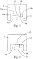
- fig. 4 another embodiment of the groove 7 of the frame structure 3 is shown.
- the groove 7 comprises a positioning element 12 that is substantially rectangular in cross section and placed such as to provide two sections 9a and 9b, each having a bottom surface 10a and 10b, respectively, and a side surface 11a and 11b, respectively.
- the side surface 11a of the section 9a is provided by a side surface of the positioning element 12, while the bottom surface 10b of the section 9b is provided by another side surface of the positioning element 12.
- the cross sectional dimensions of the positioning element 12 are chosen such as to provide the sections 9a and 9b with suitable dimensions for providing a tight fit between frame structure 3 and lining structure 2, i.e. for corresponding with the dimensions of the end portion 8 of the lining structure 2.
- the positioning element 12 is in the embodiment shown in fig. 4 a slat, a strip or the like, preferably made of wood or of a suitable plastics material, although any material suitable for providing a tight, substantially un-elastic fit between the frame structure 3 and a end portion 8 of the lining structure 2 may in principle be used.
- the positioning element 12 preferably extends throughout the whole longitudinal extension of the groove 7 along the circumferential surface 3a of the frame structure 3, which in fig. 4 corresponds to the direction into or out of the paper.
- the positioning element 12 may be one positioning element 12 extending throughout the longitudinal extension of the groove 7 or there may be provided several positioning elements 12 placed in continuation of each other along the longitudinal direction of the groove 7.
- the positioning elements 12 may be placed spaced apart along the longitudinal direction of the groove 7 with suitable, not necessarily uniform intervals.
- the positioning elements 12 may be a number of blocks or pieces of slats, strips or the like of suitable, but not necessarily identical, dimensions.
- the positioning element 12 according to fig. 4 further comprises a means for attachment 14 to the frame structure 3.
- the means for attachment 14 is shown in the form of a nail, but may in principle be any suitable means for attachment such as a screw, a bolt or the like. Furthermore, more than one means for attachment 14 may be provided, e.g. along the longitudinal extension of the positioning element 12. Also, the means for attachment 14 may comprise one or more through holes (not shown) provided in the positioning element 12 for receiving a nail, screw, bolt or the like.
- Another feasible embodiment of the means for attachment 14 is spikes or like elements embedded in and protruding from a surface of the positioning element 12 in such a way as to enable the spikes to be forced into the bottom surface of the groove 7, thus attaching the positioning element 12 to the groove 7 of the frame structure 3.
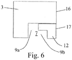
- Fig. 5 shows an embodiment of the invention similar to that of fig. 4 , the only difference being that two positioning elements 12 placed side by side in the transversal direction of the groove 7 has been provided, resulting in three placing positions 9a, 9b and 9c being available. Obviously, more than two positioning elements 12, and thereby possibly more than three placing positions may be provided. Furthermore the use of more than one positioning element provides for the possibility of on site adaptation of the dimensions (i.e. width and depth) of the placing positions to fit the specific requirements arising, however within the limitations provided by the overall width and depth of the groove 7.
- Fig. 6 shows another embodiment of the invention similar to that of fig. 4 .
- the groove 7 is provided such that it extends transversally to a side 16 of the frame structure 3, and the positioning element 12 comprises a stepped cross section.
- the positioning element is placed such that its largest side surface 17 is lying in continuation of the side surface 16 of the frame structure, thus again providing the groove 7 with two placing positions 9a and 9b.
- the groove 7 comprises a positioning element 112 in the form of a fitting attached to the bottom surface of the groove 7 with a means for attachment 14.
- the fitting is preferably made of a suitable metal such as e.g. aluminium or stainless steel.
- the means for attachment 14 may be of any of the embodiments described in the above, with or without through holes.
- the fitting 112 shown in fig. 7 is an angle iron type fitting comprising two legs 13a and 13b and is placed such as to provide two sections 9a and 9b of a rectangular cross section.
- the bottom surface 110a of the section 9a is provided by a surface of the leg 13a, whereas a surface of the leg 13b provides for the side surface 111a of the section 9a.
- the bottom surface 110b and the side surface 111b of the section 9b are provided by the bottom surface and one of the side surfaces of the groove 7.
- the fitting 112 may be one fitting extending along at least a part of the longitudinal extension of the groove 7 of the frame structure 3, or there may be several fittings 112 placed in extension or placed spaced apart of each other along the longitudinal direction of the groove 7.
- Fig. 8 shows an embodiment of the invention similar to that of fig. 7 .
- the positioning element 112 is an angle iron type fitting, but now mounted by the use of a means for attachment 114 in the form of a tapering of the end edge of a leg 13b of the fitting being wedged into the bottom of the groove 7, thus providing the sections 9a and 9b.
- the leg 13a providing the sections 9a, 9b with different depths, may in principle be omitted, the positioning element 112 then being a simple plate-shaped fitting wedged into the bottom of the groove 7.
- the positioning elements 112 could in principle be nails, screws or the like possibly having two perpendicular legs.
- Fig. 9 shows another embodiment of the invention similar to that of fig. 7 , the positioning element 112, that is again a fitting, being provided with a stepped profile comprising four legs 13a, 13b, 13c and 13d.
- the leg 13c provides for the possibility of attaching the positioning element 112 that thus covers the entire width of the groove 7 to the grove 7 by friction, i.e. by pushing the positioning element 112 into the groove 7 such that it is fixed between the side surfaces of the groove 7.
- a means for attachment 14 extending through the leg 13d is furthermore used to attach the positioning element 112 to the frame structure 3 at a side surface of the groove 7. Obviously it is, however, in principle possible to omit leg 13d and/or 13a.
- Fig. 10 shows another embodiment of the invention similar to that of fig. 7 , with a positioning element 112, being a fitting, having a stepped profile with five legs 13a - 13e.
- the groove 7 is provided such that it extends transversally to a side 16 of the frame structure 3, and the positioning element 112 is placed such that its largest side surface 17, being the side surface of the leg 13e, is lying in extension of the side surface 16 of the frame structure 3, thus again providing the groove 7 with two placing positions 9a and 9b.
- the one or more positioning element may instead be e.g. glued or moulded to the frame structure 3 in the groove 7.
- a plastics material such as polyurethane (PUR).
- the frame structure 3 is preferably provided with the groove 7 before being encased, i.e. the groove 7 is provided in the wooden core of the frame structure 3 and the frame structure 3 including the groove 7 is subsequently encased, the encasement thus following the outline of the groove 7.
- the mould used for moulding or encasing the frame structure 3 may be shaped to provide the grove 7.
- the groove 7 according to the invention may also be provided by providing an existing frame structure having a groove of a known type with a suitable recess or incision in the frame structure, which may be wooden or moulded, or in the outer shape of an encasement to be applied to a frame structure.
- the one or more positioning element 12, 112 described above may be attached to the groove 7 of the frame structure 3 either during the production of the window assembly or at a later stage, such as on site by the installer. Furthermore the positioning element 12, 112 and/or the frame structure 3 may be provided with position adjustment means (not shown) such as markings for assistance when adjusting the position of the positioning element 12, 112 prior to attaching it to the frame structure 3. Such position adjustment means may for instance be provided as markings on the frame structure adjacent to or on the bottom of the groove 7, and/or by providing the one or more through holes (not shown) as oblong holes or slots, such that the positioning element 12, 112 may be kept in place in the groove 7 using the means for attachment 14 and its position adjusted prior to the final tensioning of the means for attachment 14. It should be noted that the above description of preferred embodiments serves only as an example, and that a person skilled in the art will know that numerous variations are possible without deviating from the scope of the claims.
Landscapes
- Engineering & Computer Science (AREA)
- Civil Engineering (AREA)
- Structural Engineering (AREA)
- Architecture (AREA)
- Door And Window Frames Mounted To Openings (AREA)
- Specific Sealing Or Ventilating Devices For Doors And Windows (AREA)
Claims (12)
- Fenster- oder Türrahmenstruktur (3), wie für ein Dachfenster, wobei die Rahmenstruktur (3) an einer Seitenfläche (3a), die in der eingebauten Position des Fensters oder des Türzusammenbaus nach innen zeigt, wenigstens eine Nut (7) aufweist, die zumindest teilweise entlang des Umfangs der Rahmenstruktur (3) ausgebildet ist und die dazu angepasst ist, einen Endabschnitt (8) einer Verkleidungsstruktur (2) aufzunehmen, wobei die Nut (7) in wenigstens einem Teil ihrer länglichen Erstreckung ein Querschnittsflächenprofil mit wenigstens zwei Abschnitten (9a, 9b) aufweist, wobei jeder Abschnitt (9a, 9b) eine im Wesentlichen rechteckige Form aufweist und wobei die wenigstens zwei Abschnitte (9a, 9b) unterschiedlich tief sind, dadurch gekenn zeichnet, dass die Nut (7) wenigstens ein Positionierungselement (12) aufweist, das so angeordnet ist, dass es die wenigstens zwei Abschnitte (9a, 9b) bereitstellt, wobei das Positionierungselement (12) aus der Gruppe ausgewählt ist, die aus einer Lamelle, einem Streifen und einem Beschlag, vorzugsweise einem Winkelbeschlag, besteht.
- Fenster- oder Türrahmenstruktur nach Anspruch 1, dadurch gekennzeichnet, dass die wenigstens zwei Abschnitte (9a, 9b) unterschiedliche Breiten (wi, wo) aufweisen.
- Fenster- oder Türrahmenstruktur nach Anspruch 1 oder 2, dadurch gekennzeichnet, dass die Nut (7) eine Bodenfläche mit einem gestuften Profil mit wenigstens zwei Stufen aufweist.
- Fenster- oder Türrahmenstruktur nach einem der vorhergehenden Ansprüche, dadurch gekennzeichnet, dass das wenigstens eine Positionierungselement (12) wenigstens ein Mittel zur Befestigung (14) an der Rahmenstruktur (3) aufweist.
- Fenster- oder Türrahmenstruktur nach einem der vorhergehenden Ansprüche, dadurch gekennzeichnet, dass das wenigstens eine Positionierungselement (12) auf die Nut (7) geklebt oder an die Nut (7) angeformt ist.
- Fenster- oder Türrahmenstruktur nach einem vorhergehenden Ansprüche, dadurch gekennzeichnet, dass das Positionierungselement (12) Positionseinstellmittel aufweist.
- Fenster- oder Türrahmenstruktur nach einem der vorhergehenden Ansprüche, wobei ein innerer Abschnitt (9a) dazu ausgebildet ist, einen Endabschnitt einer ersten Verkleidung aufzunehmen, und ein äußerer Abschnitt (9b) dazu ausgebildet ist, einen Endabschnitt einer zweiten Verkleidung aufzunehmen.
- Fenster- oder Türrahmenstruktur nach Anspruch 7, wobei der erste Verkleidungsendabschnitt (8) näher an der Fensterscheibe (5) positioniert ist als der zweite Verkleidungsendabschnitt.
- Fenster- oder Türrahmenstruktur nach einem der vorhergehenden Ansprüche, wobei die Breite der Abschnitte sich über die Hälfte der Breite der Rahmenstruktur (3) oder über mehr als die Hälfte der Breite der Rahmenstruktur (3) erstreckt.
- Fenster- oder Türrahmenstruktur nach einem der vorhergehenden Ansprüche, wobei ein innerer Abschnitt (9a) für den Einbau einer ersten Verkleidung mit einem ersten, kleineren Abstand zwischen den zwei gegenüberliegenden Verkleidungsendabschnitten (8) ausgebildet ist, und wobei ein äußerer Abschnitt (9b) für den Einbau einer zweiten Verkleidung mit einem zweiten, größeren Abstand zwischen den zwei gegenüberliegenden Verkleidungsendabschnitten (8) ausgebildet ist.
- Fenster- oder Türanordnung wie eine Dachfensteranordnung (1), aufweisend eine Verkleidungsstruktur (2) und eine Rahmenstruktur (3) nach einem der Ansprüche 1 bis 10, wobei die Rahmenstruktur (3) an einer Seitenfläche (3a), die in der eingebauten Position der Fenster- oder Türanordnung nach innen zeigt, wenigstens eine Nut (7) aufweist, die zumindest teilweise entlang des Umfangs der Rahmenstruktur (3) ausgebildet ist und die dazu angepasst ist, einen Endabschnitt (8) einer Verkleidungsstruktur (2) aufzunehmen, dadurch gekennzeichnet, dass die Nut (7) in wenigstens einem Teil ihrer länglichen Erstreckung ein Querschnittsflächenprofil mit wenigstens zwei Abschnitten (9a, 9b) aufweist, wobei jeder Abschnitt (9a, 9b) eine im Wesentlichen rechteckige Form aufweist
- Verfahren zum Austauschen einer Rahmenstruktur (3) und einer Flügelstruktur (4) einer Fensteranordnung, wie einer Dachfensteranordnung (1), die in der Laibung (6a) einer Gebäudestruktur (6) verbaut ist,
wobei eine Verkleidungsstruktur (2) der Fensteranordnung in der Laibung (6a) verbaut verbleibt,
wobei das Verfahren die folgenden Schritte aufweist:Demontieren der verbauten Rahmenstruktur und der Flügelstruktur,Belassen der verbauten Verkleidungsstruktur,Bereitstellen einer neuen Fensterstruktur mit einer Rahmenstruktur (3) und einer Flügelstruktur (4), undVerbauen der neuen Fensterstruktur in der Laibung (6a),dadurch gekennzeichnet, dass die Rahmenstruktur (3) der neuen Fensterstruktur an der Seitenfläche (3a), die in der verbauten Position der Fensteranordnung nach innen zeigt, eine Nut (7) aufweist, die zumindest teilweise entlang des Umfangs der Rahmenstruktur (3) verläuft, wobei die Nut (7) dazu angepasst ist, einen Endabschnitt der Verkleidungsstruktur (2) aufzunehmen, wobei die Nut (7) zumindest in einem Teil ihrer Längserstreckung mit einem Querschnittsflächenprofil ausgestattet ist, das wenigstens zwei Abschnitte (9a, 9b) aufweist, wobei die Abschnitte jeweils eine im Wesentlichen rechteckige Form aufweisen, und dass die wenigstens zwei Abschnitte (9a, 9b) unterschiedlich tief sind, und dass die Nut (7) wenigstens ein Positionierungselement (12) aufweist, das so angeordnet ist, dass es die wenigstens zwei Abschnitte (9a, 9b) bereitstellt, wobei das Positionierungselement (12) aus der Gruppe ausgewählt ist, die aus einer Lamelle, einem Streifen, einem Beschlag, vorzugsweise einem Winkelbeschlag besteht, und dass der Schritt des Montierens der neuen Fensteranordnung (1) in der Laibung (6a) ferner vorsieht, dass ein Endabschnitt der verbliebenen Verkleidungsstruktur (2) wenigstens einen der wenigstens zwei Abschnitte (9a, 9b) der Nut (7) belegt, wobei ein innerer Abschnitt für den Einbau einer ersten Verkleidung mit einem ersten, kleineren Abstand zwischen den zwei gegenüberliegenden Verkleidungsendabschnitten ausgebildet ist und wobei ein äußerer Abschnitt für den Einbau einer zweiten Verkleidung mit einem zweiten, größeren Abstand zwischen den zwei gegenüberliegenden Verkleidungsendabschnitten ausgebildet ist.
Applications Claiming Priority (1)
| Application Number | Priority Date | Filing Date | Title |
|---|---|---|---|
| DKPA200801850 | 2008-12-30 |
Publications (3)
| Publication Number | Publication Date |
|---|---|
| EP2204524A2 EP2204524A2 (de) | 2010-07-07 |
| EP2204524A3 EP2204524A3 (de) | 2013-11-27 |
| EP2204524B1 true EP2204524B1 (de) | 2017-10-18 |
Family
ID=41796595
Family Applications (1)
| Application Number | Title | Priority Date | Filing Date |
|---|---|---|---|
| EP09179994.0A Active EP2204524B1 (de) | 2008-12-30 | 2009-12-18 | Ein Fenster oder Tür mit einer Rahmenkonstruktion mit einer Nut für ein Innenfutter |
Country Status (1)
| Country | Link |
|---|---|
| EP (1) | EP2204524B1 (de) |
Families Citing this family (5)
| Publication number | Priority date | Publication date | Assignee | Title |
|---|---|---|---|---|
| FR3063099B1 (fr) * | 2017-02-17 | 2022-02-18 | M C France | Menuiserie pour une ouverture menagee dans une paroi de batiment |
| PL4466416T3 (pl) * | 2022-03-31 | 2025-09-08 | Vkr Holding A/S | Okno dachowe mające ościeżnicę z konstrukcjami odbiorczymi |
| USD1065597S1 (en) | 2023-03-30 | 2025-03-04 | Vkr Holding A/S | Window component |
| USD1052757S1 (en) | 2023-03-30 | 2024-11-26 | Vkr Holding A/S | Window |
| EP4700200A1 (de) | 2024-08-22 | 2026-02-25 | UAB "Warmotech" | Einrastelement für beliebige fensterinstallation an das universal-thermoprofil und verfahren zu dessen verwendung |
Citations (3)
| Publication number | Priority date | Publication date | Assignee | Title |
|---|---|---|---|---|
| WO1998022682A1 (en) * | 1996-11-19 | 1998-05-28 | Velux Industri A/S | A window having an improved sash structure |
| WO2002057563A1 (en) * | 2001-01-19 | 2002-07-25 | Vkr Holding A/S | A roof window assembly and components |
| US20050086878A1 (en) * | 2003-10-24 | 2005-04-28 | Vkr Holding A/S | Flashing and mounting bracket for a skylight |
Family Cites Families (3)
| Publication number | Priority date | Publication date | Assignee | Title |
|---|---|---|---|---|
| FR2729174B1 (fr) * | 1995-01-09 | 1997-03-28 | Alcan France | Dispositif pour le montage et la fixation d'un revetement de facade. |
| DE19514149C2 (de) | 1995-04-15 | 1997-07-03 | Braas Gmbh | Bausatz für ein Anschlußfutter für einen Fensterrahmen |
| GB2439319A (en) * | 2006-06-22 | 2007-12-27 | Metal Window Co Ltd | Rooflight comprising a water deflector |
-
2009
- 2009-12-18 EP EP09179994.0A patent/EP2204524B1/de active Active
Patent Citations (3)
| Publication number | Priority date | Publication date | Assignee | Title |
|---|---|---|---|---|
| WO1998022682A1 (en) * | 1996-11-19 | 1998-05-28 | Velux Industri A/S | A window having an improved sash structure |
| WO2002057563A1 (en) * | 2001-01-19 | 2002-07-25 | Vkr Holding A/S | A roof window assembly and components |
| US20050086878A1 (en) * | 2003-10-24 | 2005-04-28 | Vkr Holding A/S | Flashing and mounting bracket for a skylight |
Also Published As
| Publication number | Publication date |
|---|---|
| EP2204524A3 (de) | 2013-11-27 |
| EP2204524A2 (de) | 2010-07-07 |
Similar Documents
| Publication | Publication Date | Title |
|---|---|---|
| US6385927B2 (en) | Decorative trim assemblies | |
| US7228663B2 (en) | Decorative trim assemblies | |
| US10119328B2 (en) | Frame structure for a window and a method for making a frame structure | |
| EP2204524A2 (de) | Ein Fenster oder Tür mit einer Rahmenkonstruktion mit einer Nut für ein Innenfutter | |
| US9945172B2 (en) | Water intrusion prevention method and apparatus | |
| US20110296651A1 (en) | Door with glass insert and method for assembling the same | |
| CA2963962A1 (en) | Modular surface covering assembly to cover a bearing surface | |
| US6463707B1 (en) | Decorative trim assemblies | |
| EP1760220B1 (de) | Dachfensterrahmen und dessen Herstellungsverfahren | |
| EP2700781B1 (de) | Fensterauskleidungsanordnung mit verbessertem Eckbeschlag | |
| EP1298277A2 (de) | Türen | |
| EP3243976B1 (de) | Plattenspleissverbinder für lineare deckenplatten | |
| CZ296197B6 (cs) | Záruben pro okno | |
| JPS6016716Y2 (ja) | シンク取付けに於けるシ−リング構造 | |
| RU2798758C1 (ru) | Рамный профиль коробки и/или створной рамы и способ его изготовления | |
| US20060042178A1 (en) | Garden window sub frame assemblies | |
| EP1715131B1 (de) | Vorrichtung zur Verwirklichung oder Erneuerung von Innentüren | |
| EP1416113A2 (de) | Rahmen mit einem Abdeckprofil | |
| EP4700200A1 (de) | Einrastelement für beliebige fensterinstallation an das universal-thermoprofil und verfahren zu dessen verwendung | |
| WO2024260641A1 (en) | Apparatus and method for installing a closure in a building | |
| AU2023203881A1 (en) | Jamb assemblies and methods for installing jamb assemblies | |
| FI85050B (fi) | Foerfarande foer montering av en huvudsakligen rektangulaer karm, t.ex. foer doerr eller foenster och en saodan karm. | |
| JP5118308B2 (ja) | シャッター装置の取付構造 | |
| GB2318378A (en) | Fixing profiled mouldings to skinned doors | |
| KR19990025660U (ko) | 폭조정가능한 문틀용 틀재 |
Legal Events
| Date | Code | Title | Description |
|---|---|---|---|
| PUAI | Public reference made under article 153(3) epc to a published international application that has entered the european phase |
Free format text: ORIGINAL CODE: 0009012 |
|
| AK | Designated contracting states |
Kind code of ref document: A2 Designated state(s): AT BE BG CH CY CZ DE DK EE ES FI FR GB GR HR HU IE IS IT LI LT LU LV MC MK MT NL NO PL PT RO SE SI SK SM TR |
|
| AX | Request for extension of the european patent |
Extension state: AL BA RS |
|
| PUAL | Search report despatched |
Free format text: ORIGINAL CODE: 0009013 |
|
| AK | Designated contracting states |
Kind code of ref document: A3 Designated state(s): AT BE BG CH CY CZ DE DK EE ES FI FR GB GR HR HU IE IS IT LI LT LU LV MC MK MT NL NO PL PT RO SE SI SK SM TR |
|
| AX | Request for extension of the european patent |
Extension state: AL BA RS |
|
| RIC1 | Information provided on ipc code assigned before grant |
Ipc: E06B 1/34 20060101AFI20131018BHEP |
|
| 17P | Request for examination filed |
Effective date: 20140527 |
|
| RBV | Designated contracting states (corrected) |
Designated state(s): AT BE BG CH CY CZ DE DK EE ES FI FR GB GR HR HU IE IS IT LI LT LU LV MC MK MT NL NO PL PT RO SE SI SK SM TR |
|
| 17Q | First examination report despatched |
Effective date: 20160913 |
|
| GRAP | Despatch of communication of intention to grant a patent |
Free format text: ORIGINAL CODE: EPIDOSNIGR1 |
|
| INTG | Intention to grant announced |
Effective date: 20170522 |
|
| GRAS | Grant fee paid |
Free format text: ORIGINAL CODE: EPIDOSNIGR3 |
|
| GRAA | (expected) grant |
Free format text: ORIGINAL CODE: 0009210 |
|
| AK | Designated contracting states |
Kind code of ref document: B1 Designated state(s): AT BE BG CH CY CZ DE DK EE ES FI FR GB GR HR HU IE IS IT LI LT LU LV MC MK MT NL NO PL PT RO SE SI SK SM TR |
|
| REG | Reference to a national code |
Ref country code: GB Ref legal event code: FG4D |
|
| REG | Reference to a national code |
Ref country code: CH Ref legal event code: EP |
|
| REG | Reference to a national code |
Ref country code: AT Ref legal event code: REF Ref document number: 938111 Country of ref document: AT Kind code of ref document: T Effective date: 20171115 Ref country code: IE Ref legal event code: FG4D |
|
| REG | Reference to a national code |
Ref country code: DE Ref legal event code: R096 Ref document number: 602009048898 Country of ref document: DE |
|
| REG | Reference to a national code |
Ref country code: NL Ref legal event code: MP Effective date: 20171018 |
|
| REG | Reference to a national code |
Ref country code: LT Ref legal event code: MG4D |
|
| REG | Reference to a national code |
Ref country code: AT Ref legal event code: MK05 Ref document number: 938111 Country of ref document: AT Kind code of ref document: T Effective date: 20171018 |
|
| PG25 | Lapsed in a contracting state [announced via postgrant information from national office to epo] |
Ref country code: NL Free format text: LAPSE BECAUSE OF FAILURE TO SUBMIT A TRANSLATION OF THE DESCRIPTION OR TO PAY THE FEE WITHIN THE PRESCRIBED TIME-LIMIT Effective date: 20171018 |
|
| PG25 | Lapsed in a contracting state [announced via postgrant information from national office to epo] |
Ref country code: NO Free format text: LAPSE BECAUSE OF FAILURE TO SUBMIT A TRANSLATION OF THE DESCRIPTION OR TO PAY THE FEE WITHIN THE PRESCRIBED TIME-LIMIT Effective date: 20180118 Ref country code: LT Free format text: LAPSE BECAUSE OF FAILURE TO SUBMIT A TRANSLATION OF THE DESCRIPTION OR TO PAY THE FEE WITHIN THE PRESCRIBED TIME-LIMIT Effective date: 20171018 Ref country code: SE Free format text: LAPSE BECAUSE OF FAILURE TO SUBMIT A TRANSLATION OF THE DESCRIPTION OR TO PAY THE FEE WITHIN THE PRESCRIBED TIME-LIMIT Effective date: 20171018 Ref country code: FI Free format text: LAPSE BECAUSE OF FAILURE TO SUBMIT A TRANSLATION OF THE DESCRIPTION OR TO PAY THE FEE WITHIN THE PRESCRIBED TIME-LIMIT Effective date: 20171018 Ref country code: ES Free format text: LAPSE BECAUSE OF FAILURE TO SUBMIT A TRANSLATION OF THE DESCRIPTION OR TO PAY THE FEE WITHIN THE PRESCRIBED TIME-LIMIT Effective date: 20171018 |
|
| PG25 | Lapsed in a contracting state [announced via postgrant information from national office to epo] |
Ref country code: LV Free format text: LAPSE BECAUSE OF FAILURE TO SUBMIT A TRANSLATION OF THE DESCRIPTION OR TO PAY THE FEE WITHIN THE PRESCRIBED TIME-LIMIT Effective date: 20171018 Ref country code: IS Free format text: LAPSE BECAUSE OF FAILURE TO SUBMIT A TRANSLATION OF THE DESCRIPTION OR TO PAY THE FEE WITHIN THE PRESCRIBED TIME-LIMIT Effective date: 20180218 Ref country code: GR Free format text: LAPSE BECAUSE OF FAILURE TO SUBMIT A TRANSLATION OF THE DESCRIPTION OR TO PAY THE FEE WITHIN THE PRESCRIBED TIME-LIMIT Effective date: 20180119 Ref country code: BG Free format text: LAPSE BECAUSE OF FAILURE TO SUBMIT A TRANSLATION OF THE DESCRIPTION OR TO PAY THE FEE WITHIN THE PRESCRIBED TIME-LIMIT Effective date: 20180118 Ref country code: AT Free format text: LAPSE BECAUSE OF FAILURE TO SUBMIT A TRANSLATION OF THE DESCRIPTION OR TO PAY THE FEE WITHIN THE PRESCRIBED TIME-LIMIT Effective date: 20171018 Ref country code: HR Free format text: LAPSE BECAUSE OF FAILURE TO SUBMIT A TRANSLATION OF THE DESCRIPTION OR TO PAY THE FEE WITHIN THE PRESCRIBED TIME-LIMIT Effective date: 20171018 |
|
| REG | Reference to a national code |
Ref country code: DE Ref legal event code: R097 Ref document number: 602009048898 Country of ref document: DE |
|
| PG25 | Lapsed in a contracting state [announced via postgrant information from national office to epo] |
Ref country code: DK Free format text: LAPSE BECAUSE OF FAILURE TO SUBMIT A TRANSLATION OF THE DESCRIPTION OR TO PAY THE FEE WITHIN THE PRESCRIBED TIME-LIMIT Effective date: 20171018 Ref country code: EE Free format text: LAPSE BECAUSE OF FAILURE TO SUBMIT A TRANSLATION OF THE DESCRIPTION OR TO PAY THE FEE WITHIN THE PRESCRIBED TIME-LIMIT Effective date: 20171018 Ref country code: CZ Free format text: LAPSE BECAUSE OF FAILURE TO SUBMIT A TRANSLATION OF THE DESCRIPTION OR TO PAY THE FEE WITHIN THE PRESCRIBED TIME-LIMIT Effective date: 20171018 Ref country code: SK Free format text: LAPSE BECAUSE OF FAILURE TO SUBMIT A TRANSLATION OF THE DESCRIPTION OR TO PAY THE FEE WITHIN THE PRESCRIBED TIME-LIMIT Effective date: 20171018 |
|
| PLBE | No opposition filed within time limit |
Free format text: ORIGINAL CODE: 0009261 |
|
| STAA | Information on the status of an ep patent application or granted ep patent |
Free format text: STATUS: NO OPPOSITION FILED WITHIN TIME LIMIT |
|
| PG25 | Lapsed in a contracting state [announced via postgrant information from national office to epo] |
Ref country code: PL Free format text: LAPSE BECAUSE OF FAILURE TO SUBMIT A TRANSLATION OF THE DESCRIPTION OR TO PAY THE FEE WITHIN THE PRESCRIBED TIME-LIMIT Effective date: 20171018 Ref country code: SM Free format text: LAPSE BECAUSE OF FAILURE TO SUBMIT A TRANSLATION OF THE DESCRIPTION OR TO PAY THE FEE WITHIN THE PRESCRIBED TIME-LIMIT Effective date: 20171018 Ref country code: RO Free format text: LAPSE BECAUSE OF FAILURE TO SUBMIT A TRANSLATION OF THE DESCRIPTION OR TO PAY THE FEE WITHIN THE PRESCRIBED TIME-LIMIT Effective date: 20171018 Ref country code: IT Free format text: LAPSE BECAUSE OF FAILURE TO SUBMIT A TRANSLATION OF THE DESCRIPTION OR TO PAY THE FEE WITHIN THE PRESCRIBED TIME-LIMIT Effective date: 20171018 |
|
| REG | Reference to a national code |
Ref country code: IE Ref legal event code: MM4A |
|
| 26N | No opposition filed |
Effective date: 20180719 |
|
| GBPC | Gb: european patent ceased through non-payment of renewal fee |
Effective date: 20180118 |
|
| PG25 | Lapsed in a contracting state [announced via postgrant information from national office to epo] |
Ref country code: MT Free format text: LAPSE BECAUSE OF NON-PAYMENT OF DUE FEES Effective date: 20171218 Ref country code: LU Free format text: LAPSE BECAUSE OF NON-PAYMENT OF DUE FEES Effective date: 20171218 |
|
| REG | Reference to a national code |
Ref country code: FR Ref legal event code: ST Effective date: 20180831 |
|
| REG | Reference to a national code |
Ref country code: BE Ref legal event code: MM Effective date: 20171231 |
|
| PG25 | Lapsed in a contracting state [announced via postgrant information from national office to epo] |
Ref country code: IE Free format text: LAPSE BECAUSE OF NON-PAYMENT OF DUE FEES Effective date: 20171218 Ref country code: FR Free format text: LAPSE BECAUSE OF NON-PAYMENT OF DUE FEES Effective date: 20180102 |
|
| PG25 | Lapsed in a contracting state [announced via postgrant information from national office to epo] |
Ref country code: GB Free format text: LAPSE BECAUSE OF NON-PAYMENT OF DUE FEES Effective date: 20180118 Ref country code: SI Free format text: LAPSE BECAUSE OF FAILURE TO SUBMIT A TRANSLATION OF THE DESCRIPTION OR TO PAY THE FEE WITHIN THE PRESCRIBED TIME-LIMIT Effective date: 20171018 Ref country code: BE Free format text: LAPSE BECAUSE OF NON-PAYMENT OF DUE FEES Effective date: 20171231 |
|
| PG25 | Lapsed in a contracting state [announced via postgrant information from national office to epo] |
Ref country code: MC Free format text: LAPSE BECAUSE OF FAILURE TO SUBMIT A TRANSLATION OF THE DESCRIPTION OR TO PAY THE FEE WITHIN THE PRESCRIBED TIME-LIMIT Effective date: 20171018 Ref country code: HU Free format text: LAPSE BECAUSE OF FAILURE TO SUBMIT A TRANSLATION OF THE DESCRIPTION OR TO PAY THE FEE WITHIN THE PRESCRIBED TIME-LIMIT; INVALID AB INITIO Effective date: 20091218 |
|
| PG25 | Lapsed in a contracting state [announced via postgrant information from national office to epo] |
Ref country code: CY Free format text: LAPSE BECAUSE OF NON-PAYMENT OF DUE FEES Effective date: 20171018 |
|
| PG25 | Lapsed in a contracting state [announced via postgrant information from national office to epo] |
Ref country code: MK Free format text: LAPSE BECAUSE OF FAILURE TO SUBMIT A TRANSLATION OF THE DESCRIPTION OR TO PAY THE FEE WITHIN THE PRESCRIBED TIME-LIMIT Effective date: 20171018 |
|
| PG25 | Lapsed in a contracting state [announced via postgrant information from national office to epo] |
Ref country code: TR Free format text: LAPSE BECAUSE OF FAILURE TO SUBMIT A TRANSLATION OF THE DESCRIPTION OR TO PAY THE FEE WITHIN THE PRESCRIBED TIME-LIMIT Effective date: 20171018 |
|
| PG25 | Lapsed in a contracting state [announced via postgrant information from national office to epo] |
Ref country code: PT Free format text: LAPSE BECAUSE OF FAILURE TO SUBMIT A TRANSLATION OF THE DESCRIPTION OR TO PAY THE FEE WITHIN THE PRESCRIBED TIME-LIMIT Effective date: 20171018 |
|
| PGFP | Annual fee paid to national office [announced via postgrant information from national office to epo] |
Ref country code: CH Payment date: 20201215 Year of fee payment: 12 |
|
| REG | Reference to a national code |
Ref country code: CH Ref legal event code: PL |
|
| PG25 | Lapsed in a contracting state [announced via postgrant information from national office to epo] |
Ref country code: LI Free format text: LAPSE BECAUSE OF NON-PAYMENT OF DUE FEES Effective date: 20211231 Ref country code: CH Free format text: LAPSE BECAUSE OF NON-PAYMENT OF DUE FEES Effective date: 20211231 |
|
| PGFP | Annual fee paid to national office [announced via postgrant information from national office to epo] |
Ref country code: DE Payment date: 20251104 Year of fee payment: 17 |