EP2204541A1 - Rotorstufe einer einteilig beschaufelten Verdichtertrommel einer axialen Strömungsmaschine und entsprechendes Herstellungsverfahren. - Google Patents
Rotorstufe einer einteilig beschaufelten Verdichtertrommel einer axialen Strömungsmaschine und entsprechendes Herstellungsverfahren. Download PDFInfo
- Publication number
- EP2204541A1 EP2204541A1 EP08172923A EP08172923A EP2204541A1 EP 2204541 A1 EP2204541 A1 EP 2204541A1 EP 08172923 A EP08172923 A EP 08172923A EP 08172923 A EP08172923 A EP 08172923A EP 2204541 A1 EP2204541 A1 EP 2204541A1
- Authority
- EP
- European Patent Office
- Prior art keywords
- hollow body
- drum
- platform
- rotor
- openings
- Prior art date
- Legal status (The legal status is an assumption and is not a legal conclusion. Google has not performed a legal analysis and makes no representation as to the accuracy of the status listed.)
- Granted
Links
Images


Classifications
-
- F—MECHANICAL ENGINEERING; LIGHTING; HEATING; WEAPONS; BLASTING
- F01—MACHINES OR ENGINES IN GENERAL; ENGINE PLANTS IN GENERAL; STEAM ENGINES
- F01D—NON-POSITIVE DISPLACEMENT MACHINES OR ENGINES, e.g. STEAM TURBINES
- F01D5/00—Blades; Blade-carrying members; Heating, heat-insulating, cooling or antivibration means on the blades or the members
- F01D5/30—Fixing blades to rotors; Blade roots ; Blade spacers
- F01D5/3061—Fixing blades to rotors; Blade roots ; Blade spacers by welding, brazing
-
- B—PERFORMING OPERATIONS; TRANSPORTING
- B23—MACHINE TOOLS; METAL-WORKING NOT OTHERWISE PROVIDED FOR
- B23K—SOLDERING OR UNSOLDERING; WELDING; CLADDING OR PLATING BY SOLDERING OR WELDING; CUTTING BY APPLYING HEAT LOCALLY, e.g. FLAME CUTTING; WORKING BY LASER BEAM
- B23K1/00—Soldering, e.g. brazing, or unsoldering
- B23K1/0008—Soldering, e.g. brazing, or unsoldering specially adapted for particular articles or work
- B23K1/0018—Brazing of turbine parts
-
- B—PERFORMING OPERATIONS; TRANSPORTING
- B23—MACHINE TOOLS; METAL-WORKING NOT OTHERWISE PROVIDED FOR
- B23K—SOLDERING OR UNSOLDERING; WELDING; CLADDING OR PLATING BY SOLDERING OR WELDING; CUTTING BY APPLYING HEAT LOCALLY, e.g. FLAME CUTTING; WORKING BY LASER BEAM
- B23K1/00—Soldering, e.g. brazing, or unsoldering
- B23K1/14—Soldering, e.g. brazing, or unsoldering specially adapted for soldering seams
- B23K1/18—Soldering, e.g. brazing, or unsoldering specially adapted for soldering seams circumferential seams, e.g. of shells
-
- B—PERFORMING OPERATIONS; TRANSPORTING
- B23—MACHINE TOOLS; METAL-WORKING NOT OTHERWISE PROVIDED FOR
- B23K—SOLDERING OR UNSOLDERING; WELDING; CLADDING OR PLATING BY SOLDERING OR WELDING; CUTTING BY APPLYING HEAT LOCALLY, e.g. FLAME CUTTING; WORKING BY LASER BEAM
- B23K15/00—Electron-beam welding or cutting
- B23K15/0046—Welding
- B23K15/0053—Seam welding
- B23K15/006—Seam welding of rectilinear seams
-
- B—PERFORMING OPERATIONS; TRANSPORTING
- B23—MACHINE TOOLS; METAL-WORKING NOT OTHERWISE PROVIDED FOR
- B23K—SOLDERING OR UNSOLDERING; WELDING; CLADDING OR PLATING BY SOLDERING OR WELDING; CUTTING BY APPLYING HEAT LOCALLY, e.g. FLAME CUTTING; WORKING BY LASER BEAM
- B23K26/00—Working by laser beam, e.g. welding, cutting or boring
- B23K26/20—Bonding
- B23K26/21—Bonding by welding
- B23K26/24—Seam welding
- B23K26/30—Seam welding of three-dimensional [3D] seams
-
- B—PERFORMING OPERATIONS; TRANSPORTING
- B23—MACHINE TOOLS; METAL-WORKING NOT OTHERWISE PROVIDED FOR
- B23K—SOLDERING OR UNSOLDERING; WELDING; CLADDING OR PLATING BY SOLDERING OR WELDING; CUTTING BY APPLYING HEAT LOCALLY, e.g. FLAME CUTTING; WORKING BY LASER BEAM
- B23K31/00—Processes relevant to this subclass, specially adapted for particular articles or purposes, but not covered by any single one of main groups B23K1/00 - B23K28/00
- B23K31/02—Processes relevant to this subclass, specially adapted for particular articles or purposes, but not covered by any single one of main groups B23K1/00 - B23K28/00 relating to soldering or welding
-
- B—PERFORMING OPERATIONS; TRANSPORTING
- B23—MACHINE TOOLS; METAL-WORKING NOT OTHERWISE PROVIDED FOR
- B23K—SOLDERING OR UNSOLDERING; WELDING; CLADDING OR PLATING BY SOLDERING OR WELDING; CUTTING BY APPLYING HEAT LOCALLY, e.g. FLAME CUTTING; WORKING BY LASER BEAM
- B23K9/00—Arc welding or cutting
- B23K9/02—Seam welding; Backing means; Inserts
- B23K9/028—Seam welding; Backing means; Inserts for curved planar seams
-
- B—PERFORMING OPERATIONS; TRANSPORTING
- B23—MACHINE TOOLS; METAL-WORKING NOT OTHERWISE PROVIDED FOR
- B23K—SOLDERING OR UNSOLDERING; WELDING; CLADDING OR PLATING BY SOLDERING OR WELDING; CUTTING BY APPLYING HEAT LOCALLY, e.g. FLAME CUTTING; WORKING BY LASER BEAM
- B23K9/00—Arc welding or cutting
- B23K9/02—Seam welding; Backing means; Inserts
- B23K9/032—Seam welding; Backing means; Inserts for three-dimensional [3D] seams
-
- F—MECHANICAL ENGINEERING; LIGHTING; HEATING; WEAPONS; BLASTING
- F01—MACHINES OR ENGINES IN GENERAL; ENGINE PLANTS IN GENERAL; STEAM ENGINES
- F01D—NON-POSITIVE DISPLACEMENT MACHINES OR ENGINES, e.g. STEAM TURBINES
- F01D5/00—Blades; Blade-carrying members; Heating, heat-insulating, cooling or antivibration means on the blades or the members
- F01D5/30—Fixing blades to rotors; Blade roots ; Blade spacers
- F01D5/3023—Fixing blades to rotors; Blade roots ; Blade spacers of radial insertion type, e.g. in individual recesses
-
- F—MECHANICAL ENGINEERING; LIGHTING; HEATING; WEAPONS; BLASTING
- F01—MACHINES OR ENGINES IN GENERAL; ENGINE PLANTS IN GENERAL; STEAM ENGINES
- F01D—NON-POSITIVE DISPLACEMENT MACHINES OR ENGINES, e.g. STEAM TURBINES
- F01D5/00—Blades; Blade-carrying members; Heating, heat-insulating, cooling or antivibration means on the blades or the members
- F01D5/34—Rotor-blade aggregates of unitary construction, e.g. formed of sheet laminae
-
- B—PERFORMING OPERATIONS; TRANSPORTING
- B23—MACHINE TOOLS; METAL-WORKING NOT OTHERWISE PROVIDED FOR
- B23K—SOLDERING OR UNSOLDERING; WELDING; CLADDING OR PLATING BY SOLDERING OR WELDING; CUTTING BY APPLYING HEAT LOCALLY, e.g. FLAME CUTTING; WORKING BY LASER BEAM
- B23K2101/00—Articles made by soldering, welding or cutting
- B23K2101/001—Turbines
-
- Y—GENERAL TAGGING OF NEW TECHNOLOGICAL DEVELOPMENTS; GENERAL TAGGING OF CROSS-SECTIONAL TECHNOLOGIES SPANNING OVER SEVERAL SECTIONS OF THE IPC; TECHNICAL SUBJECTS COVERED BY FORMER USPC CROSS-REFERENCE ART COLLECTIONS [XRACs] AND DIGESTS
- Y10—TECHNICAL SUBJECTS COVERED BY FORMER USPC
- Y10T—TECHNICAL SUBJECTS COVERED BY FORMER US CLASSIFICATION
- Y10T29/00—Metal working
- Y10T29/49—Method of mechanical manufacture
- Y10T29/49316—Impeller making
- Y10T29/4932—Turbomachine making
- Y10T29/49321—Assembling individual fluid flow interacting members, e.g., blades, vanes, buckets, on rotary support member
Definitions
- the invention relates to an axial turbomachine compressor drum, more specifically to a drum provided with several rows of blades, each row forming a stage of the compressor with a row of stator vanes directly downstream of said row.
- the blades each comprise a foot having a shape adapted to cooperate in abutment with a groove provided on the drum.
- the root of the blade having two projecting edges forming a hook is inserted in a circular groove of the drum serving as a housing for the blade roots and the blade is then rotated along its main axis so that the two edges protruding from the foot enters into positive contact, that is to say in abutment, with the two edges of the groove of the drum.
- the blade roots in particular the projecting hook parts, are dimensioned in a rather massive manner and the same is true of the flanges of the circumferential groove of the drum with which the root of the blade cooperates.
- This mass of material at the periphery of the drum induces significant centrifugal forces that the drum must be able to resume.
- These surplus centrifugal forces to resume require a more massive dimensioning of the drum and therefore a weight and a high cost.
- a lighter construction of a compressor drum is known from the patent RU 2 270 937 C1 .
- the veil of the drum is constructed by an assembly of rings or struts interconnected by rows of blade platforms.
- the rows of blade platforms form, strictly speaking, the prolongation of the veil of the drum.
- These platforms are welded together and with the intermediate sections of the veil.
- This construction lacks rigidity in itself and requires many reinforcements from the drum center to the inner face of the veil, either directly under the blades or under the intermediate sections of the veil.
- This construction is complex and long to assemble. Production costs thus remain relatively high.
- the patent application EP 1 319 842 A1 discloses a drum in several parts or sections along the axis of rotation and assembled together by screwing.
- the blades are fixed at the junctions between the sections, either by lock or directly via the screwing means.
- the blade roots have a shape with projecting edges approximately in the direction of the axis of rotation, these projecting edges cooperating with corresponding grooves on each end of the section at their level. junction.
- the blade roots in particular the projecting edges, are trapped in the opposite grooves of the sections and pressurized during the tightening of the fixing means.
- the blade roots comprise bores through which the fastening means of the sections are assembled.
- the object of the invention is to propose a compressor drum construction at least partially overcoming the aforementioned problems of the state of the art.
- the invention consists of a compressor drum rotor stage for axial turbomachine, comprising a hollow body generally symmetrical in revolution with respect to an axis of rotation corresponding to the axis of the turbomachine; a plurality of blades disposed at the periphery of the body; wherein each blade of the plurality of vanes has at its foot a mounting plate housed in a corresponding opening in the hollow body, each platform being housed in a corresponding aperture so that the outer surface of each platform substantially outcrops. with the outer surface of the hollow body at the edge of the corresponding opening; and each platform is connected to the hollow body by welding between the outer edge of the platform and the inner edge of the corresponding opening.
- This drum construction in particular assembly of the blades to the drum, allows a saving of material and therefore of substantial mass at the level of the veil.
- the material otherwise necessary to realize the massive blade roots including the fixing bulb (fitting into the notches and grooves of the drum) according to the prior art is removed, allowing an optimized distribution of thicknesses and a substantial mass gain.
- the interfaces between the blades and the drum are greatly simplified and the tolerances on the blade roots and on the receiving zones of the drum are less tight. This allows a reduction in machining costs and the number of nonconformities.
- This drum construction in particular assembly of the blades to the drum, also allows better control of the position of the blades relative to the drum, greatly reducing or even canceling the rotations in operation of the blades in the drum as it may be the case in the prior art.
- the openings are made in the hollow body so as to form at least one row on the periphery of the hollow body.
- the hollow body is in one piece, preferentially coming from the same material.
- the openings are made in the hollow body by machining.
- the apertures and the corresponding platforms have a general shape of parallelogram whose corners are rounded.
- the hollow body comprises two flanks, each generally in a plane perpendicular to the axis, one being upstream and the other downstream of the row of openings, the outer edges of the flanks being preferably close to the openings of the row.
- the ribs (extension of the upstream and downstream flanks towards the inside of the hollow body) optimize the stiffening of the drum and make it possible to better manage ovalization of the drum under nominal and extreme operating conditions.
- the hollow body comprises two inner annular ribs each forming one of the flanks upstream and downstream of the row of openings.
- the hollow body comprises a generally cylindrical portion in one piece, preferably integral with the downstream side and comprising at least one circular rib at its periphery intended to cooperate in friction with a ferrule of a stator stator forming with the row of blades of the rotor stage a compressor stage.
- an elastomer is applied to the inner face of the platforms and the inner faces of the upstream and downstream flanks to ensure damping of the vibrations of the blades and the hollow body.
- At least two opposite edges of the openings and the corresponding edges of the platforms are bevelled so as to reduce the passage section of the openings towards the interior of the hollow body, thus allowing the blades to be placed in the openings from outside the hollow body.
- connection by welding between the platforms and the openings is carried out on the entire contour of the platforms.
- connection by welding between the platforms and the openings is made from the outer surface of the hollow body.
- each blade of the plurality of blades is in one piece with its platform, preferentially material with its platform.
- the invention also relates to a compressor drum for axial turbomachine comprising at least one rotor stage as described above.
- the invention also relates to an axial turbomachine compressor comprising a drum as defined above.
- the invention also relates to an axial turbomachine comprising a compressor as defined above.
- a cylinder is inserted into the hollow body during the welding operation to protect the other parts of the drum.
- FIG. figure 1 A compressor comprising a drum according to the invention is illustrated in FIG. figure 1 .
- the rotor consists of a hollow body 1 of generally cylindrical shape in the form of a sail. This veil is generally symmetrical in revolution with respect to its axis of rotation.
- the figure 1 shows only the upper half of the rotor and stator assembly, knowing that the other lower half is symmetrical to the upper half relative to the axis of rotation.
- the same is true for the stator 4.
- the stator 4 and the rotor 1 define an annular passage for a fluid stream of air to be displaced and compressed from left to right according to the representation in FIG. figure 1 .
- the rotor comprises a blower 20 (partially shown at the extreme left of the figure) and three parallel rows of vanes 2, 2 'and 2 "These vanes are rigidly fixed to the web and thus rotate with the rotor Rows of rectifying vanes 30, 3, 3 ', 3 "are arranged between the rows of stator vanes. These rectifier vanes are rigidly fixed at their upper ends to the stator 4. Each row of stationary blades constitutes a rectifying grid whose function is to straighten the fluid flow coming from the row of vanes of the rotor directly upstream. A row of rotor blades combined with a row of directly downstream stator vanes constitutes a stage of the compressor.
- the compressor comprises four stages, the first consisting of rows of rotor blades 20 and stator 30, the second consisting of rows of rotor blades 2 and stator 3, the third consisting of rows of rotor blades 2 'and stator 3 'and the fourth consisting of rows of rotor blades 2 "and stator 3".
- a row of stator vanes 30 is present between the fan 20 and the first row of rotor blades 2. This row of vanes rectifies the fluid flow generated by the fan 20.
- the vanes 30, 3, 3 'and 3 "of the rectifiers are fixed to the outer rings of the stator 4.
- the lower ends of the vanes of each row of the stator are embedded in an inner shell 90, 9, 9', 9".
- Each ferrule is dimensioned so as to bind the vanes of the stator together and to cooperate sealingly with the rotor 1.
- each ferrule has on its inner face a brittle material more commonly referred to as the "abradable” which has , as its name suggests, the ability to break up into fine dust when rubbed with the wipers 60, 6, 6 ', 6 "of the rotor.
- These wipers are circular ribs provided on the outer surface of the rotor facing the inner ferrules 90, 9, 9 'and 9 ", respectively. These ribs extend in a plane generally perpendicular to the axis of rotation of the rotor and have a tip-shaped outer edge in order to be able to come into contact with the abradable material to ensure a certain seal while minimizing the contact surface. and therefore the friction forces.
- the compressor drum of the figure 1 is illustrated at the figure 2 .
- the drum or rotor consists of a web 1 monoblock, that is to say, in one piece.
- the drum has a general shape of axial revolution symmetry whose wall is formed by the web 1.
- the drum is typically obtained by machining a forge blank but other forming processes well known in the art can be considered.
- the web 1 is extended at the rows of rotor blades by flanks on either side of each row. Indeed, the first row of blades 2 is supported by the flanks 7 and 8. These flanks are generally annular in a plane generally perpendicular to the axis of the drum.
- flanks 7 and 8 open into the interior volume of the drum to form ribs reinforcing the drum, and the outer portions form outer flanks of the drum which form the aerodynamic vein in the extension of the inner ferrules of the upstream and downstream rectifier stages.
- the web 1 is connected to an intermediate portion of the sidewalls. The same goes for the following stages, namely that the drum is similarly extended on either side of the rows of blades 2 'and 2 "by the flanks 7', 8 ', 7" and 8 ", respectively .
- the outer surface of the drum between two adjacent flanks 7 and 8, 7 'and 8' or 7 “and 8" is generally cylindrical.
- a series of openings are made in this surface to receive, each, the platform 5 of a blade 2. These openings have a constant parallelogram shape whose corners are rounded.
- the platforms 5, 5 ', 5 "of the blades have a shape corresponding to that of the openings. is inserted into a corresponding opening and is then fixed by welding around the entire periphery of the platform.
- the platforms although generally flat may be slightly curved in one direction so as to better fit the cylindrical shape of the outer surface of the drum between two ribs. Each platform is inserted into its respective opening so that its outer surface is flush with the outer surface of the opening directly to its edge.
- the figure 3 is an elevational view of a row of blades of the drum, this view being folded in a plane corresponding to the plane of the sheet.
- This figure shows the parallelogram shape of the openings 10 and platforms 5.
- the profile 2 of the blades at the platform is well represented.
- the parallelogram shape of the openings and platforms is chosen so that the profile of the blade is more or less centered on the surface defined by the platform. The four edges of the platform are thus at a distance from the foot of the dawn.
- This arrangement has the advantage that the thermal stresses caused by the welding operation of the drum platform are not transmitted directly to the root of the blade.
- the presence of material between the openings is responsible for maintaining the shape and dimensions of the drum within fairly tight tolerances before and after the introduction of the blades, despite the welding operation.
- the openings 10 are typically made by machining. Other methods known to those skilled in the art can also be envisaged.
- the rotor blades are obtained from forging, foundry or other crude and then machined in order to put their head and their platform in shape and final dimension.
- a mounting clearance is provided between the outer edges of the platform 5 and the inner edges of the opening 10, typically of the order of a few tenths of a millimeter or even of the order of a millimeter.
- flanks 7 and 8 on each side of the row of openings are close to the upstream and downstream edges of the openings. This proximity is better illustrated in the figure 2 which shows that these flanks form an annular outward extension having approximately the width of the platforms in a direction parallel to the axis of the drum. This proximity makes it possible to resume the centrifugal efforts to which the blades are subjected.
- the distance between the inner faces of two flanks on either side of a row of blades is equal to or slightly greater than the width of the blades measured at the platform in a direction parallel to the axis of the drum, typically up to 110% of this width.
- flanks 7 and 8 also form an annular inward extension of the drum web approximately the width of the platforms in a direction parallel to the axis of the drum. These ribs allow to reinforce the stiffening of the drum and reduce the ovalization thereof in case of imbalance of the rotating mass for example during a loss of fan blade.
- the figure 3 shows that platforms and openings have a constant shape. However, platforms of different sizes and / or shapes could be considered along a row. For example, a platform could have two, three or more blades and therefore have dimensions accordingly.
- the figure 3 illustrates a constant step between the blades of a row. One could imagine to vary the pace while retaining the principle of the invention.
- the drum as illustrated in Figures 1 and 2 is in one piece, that is to say that it is for example machined from a rough forge.
- Such a drum part could then be attached to another part of the monobloc blisk type for example.
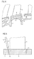
- FIG 5 is a section of the platform of a blade positioned in a drum opening ready to be welded.
- the edges of the platform and the corresponding edges of the opening are bevelled.
- the bevel is such that the platform is placed in the opening from outside the drum and the platform is prevented from overriding the opening.
- the bevel is formed by a flat surface of each edge 14 of the opening and each edge 15 of the platform inclined at an angle of a few degrees, typically between 5 and 20 °. It should be noted that it is sufficient that the faces of two opposite edges are bevelled in order to achieve the positioning advantages indicated above.
- the weld applied by the electrode 13 is made from the outside of the drum and joins the edges of the platform and the opening over the entire periphery.
- the figure 4 is an enlarged sectional view of a blade and drum part on both sides of the blade.
- An elastomer 11 is applied under the platform 5 of the blade 3 and on the adjacent inner faces of the flanks 7 and 8. This elastomer acts to damp the vibrations of the blades and the drum.
- the presence of a cavity formed by the flanks and the blade platform is particularly advantageous for the application of such an elastomer.
Landscapes
- Engineering & Computer Science (AREA)
- Mechanical Engineering (AREA)
- Physics & Mathematics (AREA)
- Plasma & Fusion (AREA)
- General Engineering & Computer Science (AREA)
- Optics & Photonics (AREA)
- Ceramic Engineering (AREA)
- Structures Of Non-Positive Displacement Pumps (AREA)
Priority Applications (4)
| Application Number | Priority Date | Filing Date | Title |
|---|---|---|---|
| EP08172923A EP2204541B1 (de) | 2008-12-24 | 2008-12-24 | Rotorstufe einer einteilig beschaufelten Verdichtertrommel einer axialen Strömungsmaschine und entsprechendes Herstellungsverfahren. |
| AT08172923T ATE548540T1 (de) | 2008-12-24 | 2008-12-24 | Rotorstufe einer einteilig beschaufelten verdichtertrommel einer axialen strömungsmaschine und entsprechendes herstellungsverfahren. |
| US12/580,070 US8414256B2 (en) | 2008-12-24 | 2009-10-15 | One-piece bladed drum of an axial turbomachine compressor |
| CA2685987A CA2685987C (en) | 2008-12-24 | 2009-11-24 | One-piece bladed drum of an axial turbomachine compressor |
Applications Claiming Priority (1)
| Application Number | Priority Date | Filing Date | Title |
|---|---|---|---|
| EP08172923A EP2204541B1 (de) | 2008-12-24 | 2008-12-24 | Rotorstufe einer einteilig beschaufelten Verdichtertrommel einer axialen Strömungsmaschine und entsprechendes Herstellungsverfahren. |
Publications (2)
| Publication Number | Publication Date |
|---|---|
| EP2204541A1 true EP2204541A1 (de) | 2010-07-07 |
| EP2204541B1 EP2204541B1 (de) | 2012-03-07 |
Family
ID=40419153
Family Applications (1)
| Application Number | Title | Priority Date | Filing Date |
|---|---|---|---|
| EP08172923A Active EP2204541B1 (de) | 2008-12-24 | 2008-12-24 | Rotorstufe einer einteilig beschaufelten Verdichtertrommel einer axialen Strömungsmaschine und entsprechendes Herstellungsverfahren. |
Country Status (4)
| Country | Link |
|---|---|
| US (1) | US8414256B2 (de) |
| EP (1) | EP2204541B1 (de) |
| AT (1) | ATE548540T1 (de) |
| CA (1) | CA2685987C (de) |
Cited By (5)
| Publication number | Priority date | Publication date | Assignee | Title |
|---|---|---|---|---|
| EP2369136B1 (de) * | 2010-03-12 | 2012-12-19 | Techspace Aero S.A. | Gewichtsreduzierte einteilige Mehrstufentrommel eines Axialverdichters |
| CN102825380A (zh) * | 2011-06-17 | 2012-12-19 | 航空技术空间股份有限公司 | 将叶片摩擦焊接至轴流压缩机的鼓的工艺及相应的装置 |
| EP2535513A1 (de) * | 2011-06-17 | 2012-12-19 | Techspace Aero S.A. | Reibschweißverfahren von Laufradschaufeln für einen Rotor einer axialen Strömungsmaschine, das an den Flucht- und Ansatzrändern der Laufradschaufeln Druckbeanspruchungen erzeugt, und entsprechender Rotor |
| CN103008902A (zh) * | 2011-09-27 | 2013-04-03 | 三星泰科威株式会社 | 旋转机器的旋转部件的接合结构及其接合方法 |
| EP2706242A1 (de) * | 2012-09-11 | 2014-03-12 | Techspace Aero S.A. | Befestigung von Laufradschaufeln auf einer Rotortrommel eines Axialkompressors |
Families Citing this family (7)
| Publication number | Priority date | Publication date | Assignee | Title |
|---|---|---|---|---|
| EP2735706B8 (de) * | 2012-11-21 | 2016-12-07 | Safran Aero Booster S.A. | Gleichrichter mit Laufradschaufeln eines Kompressors eines axialen Turbotriebwerks, und Herstellungsverfahren |
| US10598024B2 (en) * | 2014-10-16 | 2020-03-24 | United Technologies Corporation | Tandem rotor blades |
| BE1022361B1 (fr) * | 2014-11-06 | 2016-03-17 | Techspace Aero Sa | Stator mixte de compresseur de turbomachine axiale. |
| BE1023619B1 (fr) * | 2015-06-26 | 2017-05-18 | Safran Aero Boosters S.A. | Carter de compresseur de turbomachine axiale |
| US10125619B2 (en) | 2015-11-19 | 2018-11-13 | General Electric Company | Rotor assembly for use in a turbofan engine and method of assembling |
| CN110977131B (zh) * | 2019-11-25 | 2021-10-29 | 中国航发沈阳黎明航空发动机有限责任公司 | 一种转子类零件的电子束焊接变形精密控制方法 |
| FR3138829B1 (fr) * | 2022-08-11 | 2024-06-28 | Safran Aircraft Engines | Élément de protection d'un tambour de compresseur basse pression de turbomachine |
Citations (10)
| Publication number | Priority date | Publication date | Assignee | Title |
|---|---|---|---|---|
| CH238024A (de) * | 1943-08-06 | 1945-06-15 | Sulzer Ag | Schaufel für Turbomaschinen. |
| DE752921C (de) * | 1941-10-08 | 1953-05-11 | Turbinenfabrik Brueckner | Schweissbefestigung von axial beaufschlagten Schaufeln von Kreiselmaschinen, insbesondere Dampf- oder Gasturbinen, und Vorrichtung zu ihrer Durchfuehrung |
| GB776618A (en) | 1954-11-03 | 1957-06-12 | English Electric Co Ltd | Improvements in and relating to the fixing of rotor blades of axial flow turbines and compressors |
| US2944326A (en) | 1955-06-02 | 1960-07-12 | Gen Electric | Method of staking blades |
| EP0503697A1 (de) * | 1991-03-11 | 1992-09-16 | General Motors Corporation | Verfahren zur Verbindung von Turbinenschaufeln im Mehreigenschaftenturbinenrotor |
| EP1176284A2 (de) * | 2000-07-27 | 2002-01-30 | General Electric Company | Turbinenleitschaufeln mit lötmittelfreien Übergangskragen |
| EP1319842A1 (de) | 2001-12-17 | 2003-06-18 | Techspace Aero S.A. | Rotor oder rotierendes Element für Turboverdichter |
| RU2270937C1 (ru) | 2004-08-10 | 2006-02-27 | Акционерное общество открытого типа Авиамоторный научно-технический комплекс "Союз" | Осевой компрессор газотурбинного двигателя (варианты) |
| US20060045748A1 (en) * | 2004-08-30 | 2006-03-02 | Cahoon Christopher L | Weld shielding device for automated welding of impellers and blisks |
| EP1658923A2 (de) * | 2004-11-16 | 2006-05-24 | General Electronic Company | Verfahren zur Herstellung einer reparierten Leitschaufelanordnung einer Turbomaschine und reparierte Anordnung |
Family Cites Families (5)
| Publication number | Priority date | Publication date | Assignee | Title |
|---|---|---|---|---|
| US2143466A (en) * | 1937-12-31 | 1939-01-10 | Westinghouse Electric & Mfg Co | Turbine apparatus |
| US3385512A (en) * | 1966-09-13 | 1968-05-28 | Orenda Ltd | Bladed rotor |
| US3625634A (en) * | 1969-12-10 | 1971-12-07 | Gen Motors Corp | Turbomachine rotor |
| DZ3365A1 (fr) * | 2001-03-06 | 2002-09-12 | Weldshield Dev N V | Methode et appareil pour soudage bout a bout des conduites revetues |
| US6969239B2 (en) * | 2002-09-30 | 2005-11-29 | General Electric Company | Apparatus and method for damping vibrations between a compressor stator vane and a casing of a gas turbine engine |
-
2008
- 2008-12-24 EP EP08172923A patent/EP2204541B1/de active Active
- 2008-12-24 AT AT08172923T patent/ATE548540T1/de active
-
2009
- 2009-10-15 US US12/580,070 patent/US8414256B2/en active Active
- 2009-11-24 CA CA2685987A patent/CA2685987C/en active Active
Patent Citations (10)
| Publication number | Priority date | Publication date | Assignee | Title |
|---|---|---|---|---|
| DE752921C (de) * | 1941-10-08 | 1953-05-11 | Turbinenfabrik Brueckner | Schweissbefestigung von axial beaufschlagten Schaufeln von Kreiselmaschinen, insbesondere Dampf- oder Gasturbinen, und Vorrichtung zu ihrer Durchfuehrung |
| CH238024A (de) * | 1943-08-06 | 1945-06-15 | Sulzer Ag | Schaufel für Turbomaschinen. |
| GB776618A (en) | 1954-11-03 | 1957-06-12 | English Electric Co Ltd | Improvements in and relating to the fixing of rotor blades of axial flow turbines and compressors |
| US2944326A (en) | 1955-06-02 | 1960-07-12 | Gen Electric | Method of staking blades |
| EP0503697A1 (de) * | 1991-03-11 | 1992-09-16 | General Motors Corporation | Verfahren zur Verbindung von Turbinenschaufeln im Mehreigenschaftenturbinenrotor |
| EP1176284A2 (de) * | 2000-07-27 | 2002-01-30 | General Electric Company | Turbinenleitschaufeln mit lötmittelfreien Übergangskragen |
| EP1319842A1 (de) | 2001-12-17 | 2003-06-18 | Techspace Aero S.A. | Rotor oder rotierendes Element für Turboverdichter |
| RU2270937C1 (ru) | 2004-08-10 | 2006-02-27 | Акционерное общество открытого типа Авиамоторный научно-технический комплекс "Союз" | Осевой компрессор газотурбинного двигателя (варианты) |
| US20060045748A1 (en) * | 2004-08-30 | 2006-03-02 | Cahoon Christopher L | Weld shielding device for automated welding of impellers and blisks |
| EP1658923A2 (de) * | 2004-11-16 | 2006-05-24 | General Electronic Company | Verfahren zur Herstellung einer reparierten Leitschaufelanordnung einer Turbomaschine und reparierte Anordnung |
Cited By (8)
| Publication number | Priority date | Publication date | Assignee | Title |
|---|---|---|---|---|
| EP2369136B1 (de) * | 2010-03-12 | 2012-12-19 | Techspace Aero S.A. | Gewichtsreduzierte einteilige Mehrstufentrommel eines Axialverdichters |
| US8932012B2 (en) | 2010-03-12 | 2015-01-13 | Techspace Aero S.A. | Reduced monobloc multistage drum of axial compressor |
| CN102825380A (zh) * | 2011-06-17 | 2012-12-19 | 航空技术空间股份有限公司 | 将叶片摩擦焊接至轴流压缩机的鼓的工艺及相应的装置 |
| EP2535516A1 (de) * | 2011-06-17 | 2012-12-19 | Techspace Aero S.A. | Reibschweißverfahren von Laufradschaufeln für die Rotortrommel eines Axialkompressors, und entsprechende Vorrichtung |
| EP2535513A1 (de) * | 2011-06-17 | 2012-12-19 | Techspace Aero S.A. | Reibschweißverfahren von Laufradschaufeln für einen Rotor einer axialen Strömungsmaschine, das an den Flucht- und Ansatzrändern der Laufradschaufeln Druckbeanspruchungen erzeugt, und entsprechender Rotor |
| CN102825380B (zh) * | 2011-06-17 | 2015-06-24 | 航空技术空间股份有限公司 | 将叶片摩擦焊接至轴流压缩机的鼓的工艺及相应的装置 |
| CN103008902A (zh) * | 2011-09-27 | 2013-04-03 | 三星泰科威株式会社 | 旋转机器的旋转部件的接合结构及其接合方法 |
| EP2706242A1 (de) * | 2012-09-11 | 2014-03-12 | Techspace Aero S.A. | Befestigung von Laufradschaufeln auf einer Rotortrommel eines Axialkompressors |
Also Published As
| Publication number | Publication date |
|---|---|
| US8414256B2 (en) | 2013-04-09 |
| US20100158690A1 (en) | 2010-06-24 |
| EP2204541B1 (de) | 2012-03-07 |
| CA2685987A1 (en) | 2010-06-24 |
| CA2685987C (en) | 2015-10-13 |
| ATE548540T1 (de) | 2012-03-15 |
Similar Documents
| Publication | Publication Date | Title |
|---|---|---|
| EP2204541B1 (de) | Rotorstufe einer einteilig beschaufelten Verdichtertrommel einer axialen Strömungsmaschine und entsprechendes Herstellungsverfahren. | |
| EP2204547B1 (de) | Außenring und Verfahren zum Schweissen einer Leitschaufel auf diesem Außenring | |
| EP2075417B1 (de) | Plattform für ein beschaufeltes Laufrad einer Strömungsmaschine, beschaufeltes Laufrad und Kompressor oder Strömungsmaschine, die ein solches Laufrad umfassen | |
| EP2366060B1 (de) | Gebläse für ein Turbotriebwerk mit einem Auswuchtsystem mit Blindlöchern zur Unterbringung von Gewichten und zugehöriges Turbotriebwerk | |
| EP0370899B1 (de) | Schaufelplatte einer Turbine | |
| FR2695163A1 (fr) | Aube creuse pour turbomachine et son procédé de fabrication. | |
| CA2442952C (fr) | Tambour formant en particulier un rotor de turbo machine, compresseur et turbo moteur comprenant un tel tambour | |
| EP2369136B1 (de) | Gewichtsreduzierte einteilige Mehrstufentrommel eines Axialverdichters | |
| FR2963383A1 (fr) | Aube de turbomachine, rotor, turbine basse pression et turbomachine equipes d'une telle aube | |
| FR2955608A1 (fr) | Amortisseur de vibrations a lamelle et chemises entre talons d'aubes adjacentes en materiau composite d'une roue mobile de turbomachine. | |
| WO2011086313A1 (fr) | Amortisseur de vibrations a pion entre talons d'aubes adjacentes en materiau composite d'une roue mobile de turbomachine | |
| FR3102206A1 (fr) | Ensemble pour une aube de turbomachine comprenant une attache définissant une alvéole et une cale adaptée pour être reçue dans l’alvéole en même temps qu’un pied de l’aube | |
| EP2706242A1 (de) | Befestigung von Laufradschaufeln auf einer Rotortrommel eines Axialkompressors | |
| EP2694781B1 (de) | Dichtring für eine turbinenstufe einer flugzeugturbomaschine mit geschlitzten drehschutzzapfen | |
| EP2336572A1 (de) | Élément de construction et son procédé de fabrication | |
| WO2013093337A1 (fr) | Redresseur de compresseur pour turbomachine | |
| EP4143421A1 (de) | Gehäuse mit zwischenflussglättung mit monoblockstrukturarm | |
| FR2960589A1 (fr) | Roue a aubes pour une turbomachine, telle qu'un turboreacteur ou un turbopropulseur d'avion | |
| EP3751102B1 (de) | Rotor für den kompressor einer rotationsmaschine und zugehöriges fertigungsverfahren | |
| EP3683450B1 (de) | Rotoranordnung einer strömungsmaschine | |
| WO2023242490A1 (fr) | Dispositif de retenue axiale des aubes mobiles d'une turbine bp dans les alvéoles d'un disque de rotor de la turbine bp et procédé de montage de ces aubes mobiles | |
| EP4060165B1 (de) | Gehäuse für kompressor eines turbotriebwerks | |
| FR3108665A1 (fr) | Rotor de soufflante comprenant des aubes à centre de gravité en amont | |
| EP3715638B1 (de) | Hybridrotor mit einem aussenmantel, der an der ringgförmigen verbundwand anliegt | |
| FR3085994A1 (fr) | Anneau de retention axiale d'aubes pour roue mobile de turbomachine, de preference pour aeronef |
Legal Events
| Date | Code | Title | Description |
|---|---|---|---|
| PUAI | Public reference made under article 153(3) epc to a published international application that has entered the european phase |
Free format text: ORIGINAL CODE: 0009012 |
|
| AK | Designated contracting states |
Kind code of ref document: A1 Designated state(s): AT BE BG CH CY CZ DE DK EE ES FI FR GB GR HR HU IE IS IT LI LT LU LV MC MT NL NO PL PT RO SE SI SK TR |
|
| AX | Request for extension of the european patent |
Extension state: AL BA MK RS |
|
| 17P | Request for examination filed |
Effective date: 20101213 |
|
| 17Q | First examination report despatched |
Effective date: 20110125 |
|
| AKX | Designation fees paid |
Designated state(s): AT BE BG CH CY CZ DE DK EE ES FI FR GB GR HR HU IE IS IT LI LT LU LV MC MT NL NO PL PT RO SE SI SK TR |
|
| RIC1 | Information provided on ipc code assigned before grant |
Ipc: B23K 20/12 20060101ALI20110729BHEP Ipc: B23K 15/00 20060101ALI20110729BHEP Ipc: B23K 11/00 20060101ALI20110729BHEP Ipc: B23K 9/00 20060101ALI20110729BHEP Ipc: B23K 5/00 20060101ALI20110729BHEP Ipc: B23K 1/00 20060101ALI20110729BHEP Ipc: F04D 29/34 20060101ALI20110729BHEP Ipc: F04D 29/32 20060101ALI20110729BHEP Ipc: F01D 5/30 20060101AFI20110729BHEP Ipc: B23K 26/20 20060101ALI20110729BHEP Ipc: B23K 31/00 20060101ALI20110729BHEP Ipc: B23K 33/00 20060101ALI20110729BHEP Ipc: B23K 20/00 20060101ALI20110729BHEP Ipc: B23K 10/02 20060101ALI20110729BHEP Ipc: F01D 5/34 20060101ALI20110729BHEP |
|
| GRAP | Despatch of communication of intention to grant a patent |
Free format text: ORIGINAL CODE: EPIDOSNIGR1 |
|
| GRAS | Grant fee paid |
Free format text: ORIGINAL CODE: EPIDOSNIGR3 |
|
| GRAA | (expected) grant |
Free format text: ORIGINAL CODE: 0009210 |
|
| AK | Designated contracting states |
Kind code of ref document: B1 Designated state(s): AT BE BG CH CY CZ DE DK EE ES FI FR GB GR HR HU IE IS IT LI LT LU LV MC MT NL NO PL PT RO SE SI SK TR |
|
| REG | Reference to a national code |
Ref country code: GB Ref legal event code: FG4D Free format text: NOT ENGLISH |
|
| REG | Reference to a national code |
Ref country code: AT Ref legal event code: REF Ref document number: 548540 Country of ref document: AT Kind code of ref document: T Effective date: 20120315 Ref country code: CH Ref legal event code: EP |
|
| REG | Reference to a national code |
Ref country code: IE Ref legal event code: FG4D Free format text: LANGUAGE OF EP DOCUMENT: FRENCH |
|
| REG | Reference to a national code |
Ref country code: DE Ref legal event code: R096 Ref document number: 602008013907 Country of ref document: DE Effective date: 20120503 |
|
| REG | Reference to a national code |
Ref country code: NL Ref legal event code: VDEP Effective date: 20120307 |
|
| PG25 | Lapsed in a contracting state [announced via postgrant information from national office to epo] |
Ref country code: NL Free format text: LAPSE BECAUSE OF FAILURE TO SUBMIT A TRANSLATION OF THE DESCRIPTION OR TO PAY THE FEE WITHIN THE PRESCRIBED TIME-LIMIT Effective date: 20120307 Ref country code: NO Free format text: LAPSE BECAUSE OF FAILURE TO SUBMIT A TRANSLATION OF THE DESCRIPTION OR TO PAY THE FEE WITHIN THE PRESCRIBED TIME-LIMIT Effective date: 20120607 Ref country code: LT Free format text: LAPSE BECAUSE OF FAILURE TO SUBMIT A TRANSLATION OF THE DESCRIPTION OR TO PAY THE FEE WITHIN THE PRESCRIBED TIME-LIMIT Effective date: 20120307 Ref country code: HR Free format text: LAPSE BECAUSE OF FAILURE TO SUBMIT A TRANSLATION OF THE DESCRIPTION OR TO PAY THE FEE WITHIN THE PRESCRIBED TIME-LIMIT Effective date: 20120307 |
|
| LTIE | Lt: invalidation of european patent or patent extension |
Effective date: 20120307 |
|
| PG25 | Lapsed in a contracting state [announced via postgrant information from national office to epo] |
Ref country code: LV Free format text: LAPSE BECAUSE OF FAILURE TO SUBMIT A TRANSLATION OF THE DESCRIPTION OR TO PAY THE FEE WITHIN THE PRESCRIBED TIME-LIMIT Effective date: 20120307 Ref country code: GR Free format text: LAPSE BECAUSE OF FAILURE TO SUBMIT A TRANSLATION OF THE DESCRIPTION OR TO PAY THE FEE WITHIN THE PRESCRIBED TIME-LIMIT Effective date: 20120608 Ref country code: FI Free format text: LAPSE BECAUSE OF FAILURE TO SUBMIT A TRANSLATION OF THE DESCRIPTION OR TO PAY THE FEE WITHIN THE PRESCRIBED TIME-LIMIT Effective date: 20120307 |
|
| REG | Reference to a national code |
Ref country code: AT Ref legal event code: MK05 Ref document number: 548540 Country of ref document: AT Kind code of ref document: T Effective date: 20120307 |
|
| PG25 | Lapsed in a contracting state [announced via postgrant information from national office to epo] |
Ref country code: CY Free format text: LAPSE BECAUSE OF FAILURE TO SUBMIT A TRANSLATION OF THE DESCRIPTION OR TO PAY THE FEE WITHIN THE PRESCRIBED TIME-LIMIT Effective date: 20120307 |
|
| PG25 | Lapsed in a contracting state [announced via postgrant information from national office to epo] |
Ref country code: PL Free format text: LAPSE BECAUSE OF FAILURE TO SUBMIT A TRANSLATION OF THE DESCRIPTION OR TO PAY THE FEE WITHIN THE PRESCRIBED TIME-LIMIT Effective date: 20120307 Ref country code: CZ Free format text: LAPSE BECAUSE OF FAILURE TO SUBMIT A TRANSLATION OF THE DESCRIPTION OR TO PAY THE FEE WITHIN THE PRESCRIBED TIME-LIMIT Effective date: 20120307 Ref country code: EE Free format text: LAPSE BECAUSE OF FAILURE TO SUBMIT A TRANSLATION OF THE DESCRIPTION OR TO PAY THE FEE WITHIN THE PRESCRIBED TIME-LIMIT Effective date: 20120307 Ref country code: SI Free format text: LAPSE BECAUSE OF FAILURE TO SUBMIT A TRANSLATION OF THE DESCRIPTION OR TO PAY THE FEE WITHIN THE PRESCRIBED TIME-LIMIT Effective date: 20120307 Ref country code: IS Free format text: LAPSE BECAUSE OF FAILURE TO SUBMIT A TRANSLATION OF THE DESCRIPTION OR TO PAY THE FEE WITHIN THE PRESCRIBED TIME-LIMIT Effective date: 20120707 Ref country code: RO Free format text: LAPSE BECAUSE OF FAILURE TO SUBMIT A TRANSLATION OF THE DESCRIPTION OR TO PAY THE FEE WITHIN THE PRESCRIBED TIME-LIMIT Effective date: 20120307 Ref country code: SE Free format text: LAPSE BECAUSE OF FAILURE TO SUBMIT A TRANSLATION OF THE DESCRIPTION OR TO PAY THE FEE WITHIN THE PRESCRIBED TIME-LIMIT Effective date: 20120307 |
|
| PG25 | Lapsed in a contracting state [announced via postgrant information from national office to epo] |
Ref country code: SK Free format text: LAPSE BECAUSE OF FAILURE TO SUBMIT A TRANSLATION OF THE DESCRIPTION OR TO PAY THE FEE WITHIN THE PRESCRIBED TIME-LIMIT Effective date: 20120307 Ref country code: PT Free format text: LAPSE BECAUSE OF FAILURE TO SUBMIT A TRANSLATION OF THE DESCRIPTION OR TO PAY THE FEE WITHIN THE PRESCRIBED TIME-LIMIT Effective date: 20120709 |
|
| PLBE | No opposition filed within time limit |
Free format text: ORIGINAL CODE: 0009261 |
|
| STAA | Information on the status of an ep patent application or granted ep patent |
Free format text: STATUS: NO OPPOSITION FILED WITHIN TIME LIMIT |
|
| PG25 | Lapsed in a contracting state [announced via postgrant information from national office to epo] |
Ref country code: AT Free format text: LAPSE BECAUSE OF FAILURE TO SUBMIT A TRANSLATION OF THE DESCRIPTION OR TO PAY THE FEE WITHIN THE PRESCRIBED TIME-LIMIT Effective date: 20120307 Ref country code: DK Free format text: LAPSE BECAUSE OF FAILURE TO SUBMIT A TRANSLATION OF THE DESCRIPTION OR TO PAY THE FEE WITHIN THE PRESCRIBED TIME-LIMIT Effective date: 20120307 |
|
| 26N | No opposition filed |
Effective date: 20121210 |
|
| PG25 | Lapsed in a contracting state [announced via postgrant information from national office to epo] |
Ref country code: IT Free format text: LAPSE BECAUSE OF FAILURE TO SUBMIT A TRANSLATION OF THE DESCRIPTION OR TO PAY THE FEE WITHIN THE PRESCRIBED TIME-LIMIT Effective date: 20120307 |
|
| REG | Reference to a national code |
Ref country code: DE Ref legal event code: R097 Ref document number: 602008013907 Country of ref document: DE Effective date: 20121210 |
|
| PG25 | Lapsed in a contracting state [announced via postgrant information from national office to epo] |
Ref country code: ES Free format text: LAPSE BECAUSE OF FAILURE TO SUBMIT A TRANSLATION OF THE DESCRIPTION OR TO PAY THE FEE WITHIN THE PRESCRIBED TIME-LIMIT Effective date: 20120618 |
|
| PG25 | Lapsed in a contracting state [announced via postgrant information from national office to epo] |
Ref country code: BG Free format text: LAPSE BECAUSE OF FAILURE TO SUBMIT A TRANSLATION OF THE DESCRIPTION OR TO PAY THE FEE WITHIN THE PRESCRIBED TIME-LIMIT Effective date: 20120607 Ref country code: MC Free format text: LAPSE BECAUSE OF NON-PAYMENT OF DUE FEES Effective date: 20121231 |
|
| REG | Reference to a national code |
Ref country code: CH Ref legal event code: PL |
|
| REG | Reference to a national code |
Ref country code: IE Ref legal event code: MM4A |
|
| PG25 | Lapsed in a contracting state [announced via postgrant information from national office to epo] |
Ref country code: IE Free format text: LAPSE BECAUSE OF NON-PAYMENT OF DUE FEES Effective date: 20121224 Ref country code: LI Free format text: LAPSE BECAUSE OF NON-PAYMENT OF DUE FEES Effective date: 20121231 Ref country code: CH Free format text: LAPSE BECAUSE OF NON-PAYMENT OF DUE FEES Effective date: 20121231 |
|
| PG25 | Lapsed in a contracting state [announced via postgrant information from national office to epo] |
Ref country code: MT Free format text: LAPSE BECAUSE OF FAILURE TO SUBMIT A TRANSLATION OF THE DESCRIPTION OR TO PAY THE FEE WITHIN THE PRESCRIBED TIME-LIMIT Effective date: 20120307 |
|
| PG25 | Lapsed in a contracting state [announced via postgrant information from national office to epo] |
Ref country code: TR Free format text: LAPSE BECAUSE OF FAILURE TO SUBMIT A TRANSLATION OF THE DESCRIPTION OR TO PAY THE FEE WITHIN THE PRESCRIBED TIME-LIMIT Effective date: 20120307 |
|
| PG25 | Lapsed in a contracting state [announced via postgrant information from national office to epo] |
Ref country code: LU Free format text: LAPSE BECAUSE OF NON-PAYMENT OF DUE FEES Effective date: 20121224 |
|
| PG25 | Lapsed in a contracting state [announced via postgrant information from national office to epo] |
Ref country code: HU Free format text: LAPSE BECAUSE OF FAILURE TO SUBMIT A TRANSLATION OF THE DESCRIPTION OR TO PAY THE FEE WITHIN THE PRESCRIBED TIME-LIMIT Effective date: 20081224 |
|
| REG | Reference to a national code |
Ref country code: FR Ref legal event code: PLFP Year of fee payment: 8 |
|
| REG | Reference to a national code |
Ref country code: FR Ref legal event code: PLFP Year of fee payment: 9 |
|
| REG | Reference to a national code |
Ref country code: DE Ref legal event code: R081 Ref document number: 602008013907 Country of ref document: DE Owner name: SAFRAN AERO BOOSTERS S.A., BE Free format text: FORMER OWNER: TECHSPACE AERO S.A., HERSTAL, BE |
|
| REG | Reference to a national code |
Ref country code: FR Ref legal event code: CD Owner name: SAFRAN AERO BOOSTERS S.A., BE Effective date: 20170606 |
|
| REG | Reference to a national code |
Ref country code: FR Ref legal event code: PLFP Year of fee payment: 10 |
|
| PGFP | Annual fee paid to national office [announced via postgrant information from national office to epo] |
Ref country code: GB Payment date: 20251229 Year of fee payment: 18 |
|
| PGFP | Annual fee paid to national office [announced via postgrant information from national office to epo] |
Ref country code: FR Payment date: 20251222 Year of fee payment: 18 |
|
| PGFP | Annual fee paid to national office [announced via postgrant information from national office to epo] |
Ref country code: BE Payment date: 20251224 Year of fee payment: 18 |
|
| PGFP | Annual fee paid to national office [announced via postgrant information from national office to epo] |
Ref country code: DE Payment date: 20251222 Year of fee payment: 18 |