EP2204548A1 - Turbine de gaz d'échappement avec virole et turbochargeur d'échappement associé - Google Patents
Turbine de gaz d'échappement avec virole et turbochargeur d'échappement associé Download PDFInfo
- Publication number
- EP2204548A1 EP2204548A1 EP09150103A EP09150103A EP2204548A1 EP 2204548 A1 EP2204548 A1 EP 2204548A1 EP 09150103 A EP09150103 A EP 09150103A EP 09150103 A EP09150103 A EP 09150103A EP 2204548 A1 EP2204548 A1 EP 2204548A1
- Authority
- EP
- European Patent Office
- Prior art keywords
- exhaust gas
- gas turbine
- blades
- turbine
- bristles
- Prior art date
- Legal status (The legal status is an assumption and is not a legal conclusion. Google has not performed a legal analysis and makes no representation as to the accuracy of the status listed.)
- Withdrawn
Links
- 238000002485 combustion reaction Methods 0.000 description 7
- 238000004140 cleaning Methods 0.000 description 3
- 239000002184 metal Substances 0.000 description 3
- 238000000034 method Methods 0.000 description 3
- 238000005406 washing Methods 0.000 description 3
- XLYOFNOQVPJJNP-UHFFFAOYSA-N water Substances O XLYOFNOQVPJJNP-UHFFFAOYSA-N 0.000 description 2
- 238000011109 contamination Methods 0.000 description 1
- 238000001816 cooling Methods 0.000 description 1
- 230000001419 dependent effect Effects 0.000 description 1
- 230000000694 effects Effects 0.000 description 1
- 239000003344 environmental pollutant Substances 0.000 description 1
- 239000000446 fuel Substances 0.000 description 1
- 239000010763 heavy fuel oil Substances 0.000 description 1
- 239000000463 material Substances 0.000 description 1
- 231100000719 pollutant Toxicity 0.000 description 1
- 239000004071 soot Substances 0.000 description 1
- 238000011144 upstream manufacturing Methods 0.000 description 1
Images

Classifications
-
- F—MECHANICAL ENGINEERING; LIGHTING; HEATING; WEAPONS; BLASTING
- F01—MACHINES OR ENGINES IN GENERAL; ENGINE PLANTS IN GENERAL; STEAM ENGINES
- F01D—NON-POSITIVE DISPLACEMENT MACHINES OR ENGINES, e.g. STEAM TURBINES
- F01D11/00—Preventing or minimising internal leakage of working-fluid, e.g. between stages
- F01D11/08—Preventing or minimising internal leakage of working-fluid, e.g. between stages for sealing space between rotor blade tips and stator
- F01D11/12—Preventing or minimising internal leakage of working-fluid, e.g. between stages for sealing space between rotor blade tips and stator using a rubstrip, e.g. erodible. deformable or resiliently-biased part
- F01D11/127—Preventing or minimising internal leakage of working-fluid, e.g. between stages for sealing space between rotor blade tips and stator using a rubstrip, e.g. erodible. deformable or resiliently-biased part with a deformable or crushable structure, e.g. honeycomb
-
- F—MECHANICAL ENGINEERING; LIGHTING; HEATING; WEAPONS; BLASTING
- F01—MACHINES OR ENGINES IN GENERAL; ENGINE PLANTS IN GENERAL; STEAM ENGINES
- F01D—NON-POSITIVE DISPLACEMENT MACHINES OR ENGINES, e.g. STEAM TURBINES
- F01D11/00—Preventing or minimising internal leakage of working-fluid, e.g. between stages
- F01D11/08—Preventing or minimising internal leakage of working-fluid, e.g. between stages for sealing space between rotor blade tips and stator
- F01D11/12—Preventing or minimising internal leakage of working-fluid, e.g. between stages for sealing space between rotor blade tips and stator using a rubstrip, e.g. erodible. deformable or resiliently-biased part
- F01D11/122—Preventing or minimising internal leakage of working-fluid, e.g. between stages for sealing space between rotor blade tips and stator using a rubstrip, e.g. erodible. deformable or resiliently-biased part with erodable or abradable material
-
- F—MECHANICAL ENGINEERING; LIGHTING; HEATING; WEAPONS; BLASTING
- F16—ENGINEERING ELEMENTS AND UNITS; GENERAL MEASURES FOR PRODUCING AND MAINTAINING EFFECTIVE FUNCTIONING OF MACHINES OR INSTALLATIONS; THERMAL INSULATION IN GENERAL
- F16J—PISTONS; CYLINDERS; SEALINGS
- F16J15/00—Sealings
- F16J15/16—Sealings between relatively-moving surfaces
- F16J15/32—Sealings between relatively-moving surfaces with elastic sealings, e.g. O-rings
- F16J15/3284—Sealings between relatively-moving surfaces with elastic sealings, e.g. O-rings characterised by their structure; Selection of materials
- F16J15/3288—Filamentary structures, e.g. brush seals
-
- F—MECHANICAL ENGINEERING; LIGHTING; HEATING; WEAPONS; BLASTING
- F05—INDEXING SCHEMES RELATING TO ENGINES OR PUMPS IN VARIOUS SUBCLASSES OF CLASSES F01-F04
- F05D—INDEXING SCHEME FOR ASPECTS RELATING TO NON-POSITIVE-DISPLACEMENT MACHINES OR ENGINES, GAS-TURBINES OR JET-PROPULSION PLANTS
- F05D2220/00—Application
- F05D2220/40—Application in turbochargers
-
- F—MECHANICAL ENGINEERING; LIGHTING; HEATING; WEAPONS; BLASTING
- F05—INDEXING SCHEMES RELATING TO ENGINES OR PUMPS IN VARIOUS SUBCLASSES OF CLASSES F01-F04
- F05D—INDEXING SCHEME FOR ASPECTS RELATING TO NON-POSITIVE-DISPLACEMENT MACHINES OR ENGINES, GAS-TURBINES OR JET-PROPULSION PLANTS
- F05D2240/00—Components
- F05D2240/55—Seals
- F05D2240/56—Brush seals
Definitions
- the invention relates to the field of exhaust gas turbochargers for supercharged internal combustion engines.
- the exhaust gas turbine of an exhaust gas turbocharger, wherein the exhaust gas turbine comprises a turbine wheel with blades and a cover ring radially surrounding the blades.
- Exhaust gas turbochargers are used to increase the performance of internal combustion engines, in particular reciprocating engines.
- an exhaust gas turbocharger usually has a centrifugal compressor and a radial or axial turbine. From a certain size it makes sense to use axial turbines for the drive of the compressor. So that the exhaust gas can not bypass the blades of the axial turbine, they are surrounded by a housing part radially outward. This housing part thus limits the flow channel radially outward in the region of the rotor blades.
- This housing part can be formed as an integral part of a diffuser arranged downstream of the rotor blades, as an integral component of a radially outer housing wall of a nozzle ring arranged upstream of the rotor blades, or as a separate component.
- the exhaust gas is heavily contaminated with soot, ash and other pollutants. These are deposited over time on certain components of the exhaust gas turbine, in particular on the blades, the cover, the guide vanes of the nozzle ring and the diffuser, and reduce the efficiency of the exhaust gas turbine, which reduces the overall performance of the internal combustion engine. For this reason, the soiled components of the exhaust gas turbine must be cleaned at regular intervals. Usually, the Exhaust gas turbine washed with water. In order to minimize the burden on the contaminated components, turbocharger manufacturers dictate that the load on the internal combustion engine be reduced during the wash cycle. As a result, the temperature of the affected components is already slightly reduced before the washing process, resulting in smaller loads.
- the CH 35 11 42 discloses an axial turbine having a turbine wheel with blades and a cover ring radially surrounding the blades, wherein the cover ring is divided into a plurality of separate segments.
- the EP 1 895 107 A1 discloses a cover ring radially outside the blades of the turbine wheel, which is also divided by slots in a plurality of circumferentially separated ring segments.
- the slots between the segments have between the inside and the outside of a deviating from the radial course.
- the cover loses its tangential context. Thus, the cover pulls in a sudden cooling, as occurs in turbine washing, no longer together in the radial direction. This is intended to reduce a strip of the blades on the cover ring.
- the object of the present invention is to further improve an exhaust gas turbine of an exhaust gas turbocharger, so that it withstands cleaning operations under full load without signs of wear on the components of the exhaust gas turbine.
- the cover ring is formed radially outside the blades of the turbine wheel as a brush with a support ring and a plurality of free-standing bristles.
- the brush is advantageously made of metal.
- the bristles can be manufactured as individual wires - per bristle in each case a thin, long, bendable piece of metal with a circular, flat, square or otherwise profiled cross section - or as twisted strands - each strand is twisted several individual wires per bristle.
- the brush as a cover ring has the advantage that in a contact between the blade tips and the bristles there is no material removal on the cover ring or on the blades, as the bristles can bend in the running direction of the blades.
- the bristles may be slightly inclined in the radial direction or deviating from the radial direction in the direction of rotation of the blades.
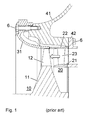
- Fig. 1 shows a section through the axis of an axial turbine of a turbocharger according to the prior art.
- the turbine wheel 10 rotatably mounted in a housing includes a hub 11 and a plurality of blades 12 disposed thereon.
- the exhaust flow needed to drive the turbine is transmitted through a flow channel from the gas inlet housing 42 via the nozzle ring 20 to the blades of the turbine wheel and further through the diffuser 31 led to the gas outlet housing 41.
- the nozzle ring 20 includes an inner wall 21 and an outer wall 22 and vanes 23 disposed therebetween.
- the walls of the nozzle ring as well as the diffuser are housing parts which define the flow channel of the exhaust gas.
- the flow channel in the region of the rotor blades is delimited by a cover ring radially enclosing the rotor blades.
- This housing part can, as in the Fig. 1 , be formed as an integral part of the downstream of the blades arranged diffuser 31.
- the cover ring may be formed as an integral part of the radially outer housing wall 22 of the nozzle ring or as an independent component.
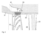
- Fig. 2 shows a section through the axis of an axial turbine of an exhaust gas turbocharger with a trained according to the invention as a brush cover ring, which the Flow channel in the region radially outside the blades 12 of the turbine wheel limited.
- the present invention designed as a brush cover ring consists of a circumferential outer ring 52, which can be positively or non-positively, for example, as shown by means of fasteners 53, attached to the housing 41.
- the ring 52 carries against radially inner a plurality of bristles 51, which close together give a flexible cover of the flow channel.
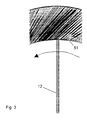
- the bristles 51 may be strictly radially aligned or, unlike the radial direction, may be inclined in the direction of the rotating blades, as shown schematically in FIG Fig. 3 is indicated.
- the support ring 52 and the bristles 51 of the brush are advantageously made of metal.
- the bristles can, as in the execution according to Fig. 4 be formed as a thin, untwisted individual wires. Alternatively, as in the embodiment according to Fig. 5 , in each case several individual wires are twisted into a strand per bristle.
- the individual bristles can be of the same length or different lengths.
- the bristles can also be of different lengths in the axial direction of the brush, that is, in the flow direction of the exhaust gas through the flow channel of the turbines. Any excess lengths can be ground away from the blade tips in a grinding process.
- the inventive exhaust gas turbine can be used instead of driving a compressor as a power turbine, about to drive an electric generator or a mechanical machine.
Landscapes
- Engineering & Computer Science (AREA)
- General Engineering & Computer Science (AREA)
- Mechanical Engineering (AREA)
- Supercharger (AREA)
Priority Applications (1)
| Application Number | Priority Date | Filing Date | Title |
|---|---|---|---|
| EP09150103A EP2204548A1 (fr) | 2009-01-06 | 2009-01-06 | Turbine de gaz d'échappement avec virole et turbochargeur d'échappement associé |
Applications Claiming Priority (1)
| Application Number | Priority Date | Filing Date | Title |
|---|---|---|---|
| EP09150103A EP2204548A1 (fr) | 2009-01-06 | 2009-01-06 | Turbine de gaz d'échappement avec virole et turbochargeur d'échappement associé |
Publications (1)
| Publication Number | Publication Date |
|---|---|
| EP2204548A1 true EP2204548A1 (fr) | 2010-07-07 |
Family
ID=40668109
Family Applications (1)
| Application Number | Title | Priority Date | Filing Date |
|---|---|---|---|
| EP09150103A Withdrawn EP2204548A1 (fr) | 2009-01-06 | 2009-01-06 | Turbine de gaz d'échappement avec virole et turbochargeur d'échappement associé |
Country Status (1)
| Country | Link |
|---|---|
| EP (1) | EP2204548A1 (fr) |
Cited By (1)
| Publication number | Priority date | Publication date | Assignee | Title |
|---|---|---|---|---|
| EP2853783A1 (fr) * | 2013-09-20 | 2015-04-01 | MTU Aero Engines GmbH | Ensemble joint-brosse et procédé de fabrication d'un ensemble joint-brosse |
Citations (11)
| Publication number | Priority date | Publication date | Assignee | Title |
|---|---|---|---|---|
| CH351142A (de) | 1955-08-18 | 1960-12-31 | Bmw Triebwerkbau Ges Mit Besch | Feststehender Abdeckring mit Dichtelementen um die Laufradschaufelenden einer Gasturbine |
| GB2139293A (en) * | 1983-05-06 | 1984-11-07 | Mtu Muenchen Gmbh | Abradable coating for a turbo compressor stutor/rotor assembly |
| JPH0441901A (ja) * | 1990-06-01 | 1992-02-12 | Hitachi Ltd | タービン動翼の構造 |
| DE4432685C1 (de) * | 1994-09-14 | 1995-11-23 | Mtu Muenchen Gmbh | Anlaufbelaf für das Gehäuse einer Turbomaschine und Verfahren zur Herstellung |
| US20020081195A1 (en) * | 2000-12-21 | 2002-06-27 | Wolfe Christopher Edward | Bucket tip brush seals in steam tubines and methods of installation |
| EP1270876A2 (fr) * | 2001-06-18 | 2003-01-02 | General Electric Company | Joint d'étanchéité abradable supporté par des ressorts élastiques |
| US20050006851A1 (en) * | 2003-07-09 | 2005-01-13 | Addis Mark E. | Brush seal with windage control |
| DE102004038933A1 (de) * | 2004-08-11 | 2006-02-23 | Mtu Aero Engines Gmbh | Dichtungsanordnung |
| US20070187900A1 (en) * | 2004-05-04 | 2007-08-16 | Advanced Components & Materials, Inc. | Non-metallic brush seals |
| EP1820938A1 (fr) | 2006-02-20 | 2007-08-22 | ABB Turbo Systems AG | Eléments de nettoyage sur les extrémités des aubes d' une turbine |
| EP1895107A1 (fr) | 2006-08-29 | 2008-03-05 | ABB Turbo Systems AG | Turbine à gaz d'échappement avec un anneau segmenté |
-
2009
- 2009-01-06 EP EP09150103A patent/EP2204548A1/fr not_active Withdrawn
Patent Citations (11)
| Publication number | Priority date | Publication date | Assignee | Title |
|---|---|---|---|---|
| CH351142A (de) | 1955-08-18 | 1960-12-31 | Bmw Triebwerkbau Ges Mit Besch | Feststehender Abdeckring mit Dichtelementen um die Laufradschaufelenden einer Gasturbine |
| GB2139293A (en) * | 1983-05-06 | 1984-11-07 | Mtu Muenchen Gmbh | Abradable coating for a turbo compressor stutor/rotor assembly |
| JPH0441901A (ja) * | 1990-06-01 | 1992-02-12 | Hitachi Ltd | タービン動翼の構造 |
| DE4432685C1 (de) * | 1994-09-14 | 1995-11-23 | Mtu Muenchen Gmbh | Anlaufbelaf für das Gehäuse einer Turbomaschine und Verfahren zur Herstellung |
| US20020081195A1 (en) * | 2000-12-21 | 2002-06-27 | Wolfe Christopher Edward | Bucket tip brush seals in steam tubines and methods of installation |
| EP1270876A2 (fr) * | 2001-06-18 | 2003-01-02 | General Electric Company | Joint d'étanchéité abradable supporté par des ressorts élastiques |
| US20050006851A1 (en) * | 2003-07-09 | 2005-01-13 | Addis Mark E. | Brush seal with windage control |
| US20070187900A1 (en) * | 2004-05-04 | 2007-08-16 | Advanced Components & Materials, Inc. | Non-metallic brush seals |
| DE102004038933A1 (de) * | 2004-08-11 | 2006-02-23 | Mtu Aero Engines Gmbh | Dichtungsanordnung |
| EP1820938A1 (fr) | 2006-02-20 | 2007-08-22 | ABB Turbo Systems AG | Eléments de nettoyage sur les extrémités des aubes d' une turbine |
| EP1895107A1 (fr) | 2006-08-29 | 2008-03-05 | ABB Turbo Systems AG | Turbine à gaz d'échappement avec un anneau segmenté |
Cited By (2)
| Publication number | Priority date | Publication date | Assignee | Title |
|---|---|---|---|---|
| EP2853783A1 (fr) * | 2013-09-20 | 2015-04-01 | MTU Aero Engines GmbH | Ensemble joint-brosse et procédé de fabrication d'un ensemble joint-brosse |
| US10100655B2 (en) | 2013-09-20 | 2018-10-16 | MTU Aero Engines AG | Brush seal and method for producing a brush seal |
Similar Documents
| Publication | Publication Date | Title |
|---|---|---|
| DE19615237C2 (de) | Abgasturbolader für eine Brennkraftmaschine | |
| EP2179143B1 (fr) | Refroidissement de fente entre une paroi de chambre de combustion et une paroi de turbine d'une installation de turbine à gaz | |
| EP2824282A1 (fr) | Turbine à gaz avec système de refroidissement de turbine à haute pression | |
| EP2194277A1 (fr) | Stabilisateur de compresseur | |
| DE2257793A1 (de) | Verdichter zur aufladung einer brennkraftmaschine | |
| EP3682092B1 (fr) | Turbine à gaz d'échappement avec diffuseur | |
| EP2101040A2 (fr) | Turbomachine dotée d'un ensemble rotor multiflux | |
| DE10028733A1 (de) | Abgasturbine für einen Turbolader | |
| DE19618313A1 (de) | Axialturbine eines Abgasturboladers | |
| EP2821596A1 (fr) | Admission d'air d'un compresseur d'un turbocompresseur à gaz d'échappement | |
| EP2112332B1 (fr) | Anneau support de distributeur avec canal pressurisé | |
| EP2781699B1 (fr) | Dispositif de nettoyage d'une turbine à gaz d'échappement | |
| EP2562430A1 (fr) | Procédé de nettoyage d'un compresseur axial | |
| EP2204548A1 (fr) | Turbine de gaz d'échappement avec virole et turbochargeur d'échappement associé | |
| WO2016001002A1 (fr) | Zone d'évacuation d'une turbine d'un turbocompresseur à gaz d'échappement | |
| EP2725203A1 (fr) | Conduite d'air froid dans une structure de boîtier d'une turbomachine | |
| EP1673519B1 (fr) | Dispositif d'etancheite pour une turbine a gaz | |
| DE102015215207A1 (de) | Brennkammer für eine Gasturbine und Hitzeschildelement zum Auskleiden einer derartigen Brennkammer | |
| DE102013220455A1 (de) | Gasturbinentriebwerk mit Kühlluftringkammer | |
| EP2781695A1 (fr) | Aubes de guidage d'une turbine à gaz d'échappement | |
| DE102011051477A1 (de) | Verfahren und Vorrichtung zum Zusammenbau von Rotationsmaschinen | |
| EP1895107A1 (fr) | Turbine à gaz d'échappement avec un anneau segmenté | |
| DE102011107557A1 (de) | Strömungspumpe | |
| EP2687684A1 (fr) | Revêtement abradable avec rainures spiralées dans une turbomachine | |
| EP2572108B1 (fr) | Compresseur centrifuge |
Legal Events
| Date | Code | Title | Description |
|---|---|---|---|
| PUAI | Public reference made under article 153(3) epc to a published international application that has entered the european phase |
Free format text: ORIGINAL CODE: 0009012 |
|
| AK | Designated contracting states |
Kind code of ref document: A1 Designated state(s): AT BE BG CH CY CZ DE DK EE ES FI FR GB GR HR HU IE IS IT LI LT LU LV MC MK MT NL NO PL PT RO SE SI SK TR |
|
| AX | Request for extension of the european patent |
Extension state: AL BA RS |
|
| AKY | No designation fees paid | ||
| REG | Reference to a national code |
Ref country code: DE Ref legal event code: R108 Effective date: 20110215 Ref country code: DE Ref legal event code: 8566 |
|
| STAA | Information on the status of an ep patent application or granted ep patent |
Free format text: STATUS: THE APPLICATION IS DEEMED TO BE WITHDRAWN |
|
| 18D | Application deemed to be withdrawn |
Effective date: 20110108 |