EP2204573A1 - Brennstoffzufuhrsystem - Google Patents
Brennstoffzufuhrsystem Download PDFInfo
- Publication number
- EP2204573A1 EP2204573A1 EP08022495A EP08022495A EP2204573A1 EP 2204573 A1 EP2204573 A1 EP 2204573A1 EP 08022495 A EP08022495 A EP 08022495A EP 08022495 A EP08022495 A EP 08022495A EP 2204573 A1 EP2204573 A1 EP 2204573A1
- Authority
- EP
- European Patent Office
- Prior art keywords
- fuel
- fuel rail
- cylinder head
- supply system
- fuel supply
- Prior art date
- Legal status (The legal status is an assumption and is not a legal conclusion. Google has not performed a legal analysis and makes no representation as to the accuracy of the status listed.)
- Withdrawn
Links
Images

Classifications
-
- F—MECHANICAL ENGINEERING; LIGHTING; HEATING; WEAPONS; BLASTING
- F02—COMBUSTION ENGINES; HOT-GAS OR COMBUSTION-PRODUCT ENGINE PLANTS
- F02M—SUPPLYING COMBUSTION ENGINES IN GENERAL WITH COMBUSTIBLE MIXTURES OR CONSTITUENTS THEREOF
- F02M69/00—Low-pressure fuel-injection apparatus ; Apparatus with both continuous and intermittent injection; Apparatus injecting different types of fuel
- F02M69/46—Details, component parts or accessories not provided for in, or of interest apart from, the apparatus covered by groups F02M69/02 - F02M69/44
- F02M69/462—Arrangement of fuel conduits, e.g. with valves for maintaining pressure in the pipes after the engine being shut-down
- F02M69/465—Arrangement of fuel conduits, e.g. with valves for maintaining pressure in the pipes after the engine being shut-down of fuel rails
-
- F—MECHANICAL ENGINEERING; LIGHTING; HEATING; WEAPONS; BLASTING
- F02—COMBUSTION ENGINES; HOT-GAS OR COMBUSTION-PRODUCT ENGINE PLANTS
- F02M—SUPPLYING COMBUSTION ENGINES IN GENERAL WITH COMBUSTIBLE MIXTURES OR CONSTITUENTS THEREOF
- F02M55/00—Fuel-injection apparatus characterised by their fuel conduits or their venting means; Arrangements of conduits between fuel tank and pump F02M37/00
- F02M55/02—Conduits between injection pumps and injectors, e.g. conduits between pump and common-rail or conduits between common-rail and injectors
- F02M55/025—Common rails
Definitions
- the invention relates to a fuel supply system for providing a combustion engine with fuel.
- Fuel supply systems are in widespread use, in particular for internal combustion engines.
- a fuel accumulator to which fuel injectors are connected and which has a relatively large volume.
- a fuel accumulator is often referred to as a common rail or a fuel rail.
- Fuel rails often comprise a hollow body with recesses, wherein the fuel injectors are arranged. Fuel can be supplied to the internal combustion engine by the fuel supply system through the fuel injector. The fuel rail can be coupled to a cylinder head of the internal combustion engine in different manners.
- the object of the invention is to create a fuel supply system for providing a combustion engine with fuel which is simply to be manufactured and which facilitates a reliable and precise connection between the fuel rail and the cylinder head.
- the invention is distinguished by a fuel supply system of a combustion engine.
- the fuel supply system comprises a fuel rail having a main body with a central longitudinal axis and an inner cavity, a cylinder head, a coupling recess penetrating the inner cavity and the main body of the fuel rail and having an axis extending substantially perpendicular to the central longitudinal axis, a tube being arranged in the coupling recess of the fuel rail in the direction of the axis and being fixedly coupled to the main body of the fuel rail in a fluid-tight manner, and a fixing element.
- the fixing element has a head portion, and the fuel rail is arranged between the head portion and the cylinder head. The fixing element extends through the tube and is in engagement with the cylinder head in a manner that the fuel rail is fixedly coupled to the cylinder head.
- the fixing element is a screw element with a male thread portion.
- the male thread portion is in engagement with a female thread portion which is arranged in the cylinder head.
- a deformation element is arranged between the head portion of the fixing element and the fuel rail.
- the deformation element is a bended sheet element.
- a distance element is arranged between the fuel rail and the cylinder head. This has the advantage that a defined distance between the fuel rail and the cylinder head can be kept. Furthermore, a transmission of forces from the head portion of the fixing element via the fuel rail and the distance element to the cylinder head is possible.
- the distance element comprises a tube and the fixing element extends through the distance element.
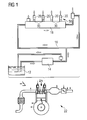
- Figure 1 shows a fuel feed device which is assigned to an internal combustion engine 22 which can be a diesel engine or a gasoline engine.
- a fuel tank 12 is connected to a fuel pump 14 via a first fuel line.
- the output of the fuel pump 14 is connected to a fuel inlet 16 of a fuel rail 18.
- the fuel is stored for example under a pressure of about 200 bar in the case of a gasoline engine or of about 2,000 bar in the case of a diesel engine.
- Fuel injectors 20 are connected to the fuel rail 18 and the fuel is fed to the fuel injectors 20 via the fuel rail 18.
- the fuel injectors 20 are arranged in a cylinder head 24 of the internal combustion engine 22.
- FIGS 2 and 3 show a fuel supply system 50.
- the fuel rail 18 is mechanically coupled of to the cylinder head 24 of the internal combustion engine 22.
- Figure 2 shows a longitudinal section through the fuel supply system 50.
- the fuel rail 18 has a cylindrical main body 25 with an inner cavity 26 which forms an inner surface of the main body 25.
- the cross section of the main body 25 can be of any shape, in particular of a square shape or a circular shape as shown in Figure 3 .
- the main body 25 has a central longitudinal axis L and is designed to contain fuel.
- a coupling recess 27 penetrates the inner cavity 26 and the main body 25 of the fuel rail 18.
- the coupling recess 27 has a longitudinal axis A which extends basically perpendicular to the central longitudinal axis L of the main body 25 of the fuel rail 18.
- the coupling recess 27 comprises two openings in the main body 25 of the fuel rail 18 being arranged at the axial ends of the coupling recess 27.
- the fuel supply system 50 comprises a tube 28 which is arranged in the coupling recess 27. That means that the tube 28 extends through the inner cavity 26 of the fuel rail 18.
- the tube 28 is arranged basically perpendicular to the central longitudinal axis L of the main body 25 of the fuel rail 18 in direction of the longitudinal axis A of the coupling recess 27.
- the length of the tube 28 in direction of the axis A is approximately equal to the diameter of the main body 25 of the fuel rail 18.
- collars 31 are arranged at the axial ends of the tube 28.
- the collars 31 are fixedly coupled to the main body 25 of the fuel rail 18, preferably by welding or brazing. This enables a fluid-proof connection between the tube 28 and the fuel rail 18.
- a fuel injector cup 30 is mechanically and hydraulically coupled to the fuel rail 18. Furthermore, the fuel injector cup 30 is in engagement with a fuel inlet portion of the fuel injector 20. A sealing ring is arranged between the fuel injector cup 30 and the fuel injector 20 to sealingly couple the fuel injector 20 to the fuel injector cup 30.
- the distance element 32 has the shape of hollow cylinder and takes up portions of the main body 25 of the fuel rail 18, as can be seen in Figure 3 . Consequently, a defined distance between the fuel rail 18 and the cylinder head 24 can be obtained.
- the fuel supply system 50 further comprises a fixing element 34 which has a head portion 36 and a pin-shaped portion.
- the fixing element 34 is a screw element with the head portion 36 and a male thread portion 38.
- the fixing element 34 extends through the tube 28 and engages the cylinder head 24.
- the head portion 36 is arranged at a part of an outer surface of the main body 25 facing away from the cylinder head 24. This means that the main body 25 of the fuel rail 18 is arranged between the head portion 36 and the cylinder head 24.
- the cylinder head 24 has a recess 40 with a female thread portion 42.
- the male thread portion 38 of the fixing element 34 is in engagement with the female thread portion 42 arranged in the cylinder head 24.
- a deformation element 48 is arranged between the head portion 36 of the fixing element 34 and the fuel rail 18 .
- the deformation element 48 absorbs forces which appear between the head portion 36 and the fuel rail 18. For example, forces which appear due to the tightening torque on the fixing element 34 to screw the male thread portion 38 into the female thread portion 42 in the cylinder head 24 can be kept away from the fuel rail 18.
- the deformation element 48 is formed as a bended sheet element, so that a low mass of the deformation element 48 can be obtained. Furthermore, a bended sheet element can have a high potential of deformation.
- the fuel supply system 50 as described allows a compact construction of the assembly of the fuel rail 18 and the cylinder head 24. Therefore, only little space is required for these components. Furthermore, the fuel supply system 50 can have a little mass. Finally, a direct transmission of forces from the fixing element 34 to the fuel rail 18 and the cylinder head 24 can be obtained.
- the tube 28 is inserted into the coupling recess 27 of the fuel rail 18 and the collars 31 of the tube 28 are brazed to the main body 25 of the fuel rail 18. By this the tube 28 can be fixedly coupled to the main body 25 of the fuel rail 18 in a manner that the fuel is contained in a proof manner in the inner cavity 26 of the fuel rail 18.
- the distance element 32 is fixedly coupled to the main body 25 of the fuel rail 18. Preferably this is carried out be brazing or welding.
- the fuel rail 18 and the distance element 32 are arranged on the cylinder head 24 in a manner that the tube 28, the distance element 32 and the recess 40 in the cylinder head 24 are aligned on the common longitudinal axis A.
- the deformation element 48 is arranged on the main body 25, and the fixing element 34 is passed through the deformation element 48 and inserted into the tube 28 and the distance element 32. Then the fixing element 34 is screwed into the recess 40 in the cylinder head 24. Due to the tightening torque acting on the head portion 36 of the fixing element 34 the deformation element 48 can be deformed. Thereby the forces caused by the tightening torque are distributed and the stress acting on the main body 25 of the fuel rail 18 and/or the tube 28 can be kept very small.
Landscapes
- Engineering & Computer Science (AREA)
- Chemical & Material Sciences (AREA)
- Combustion & Propulsion (AREA)
- Mechanical Engineering (AREA)
- General Engineering & Computer Science (AREA)
- Fuel-Injection Apparatus (AREA)
Priority Applications (1)
| Application Number | Priority Date | Filing Date | Title |
|---|---|---|---|
| EP08022495A EP2204573A1 (de) | 2008-12-29 | 2008-12-29 | Brennstoffzufuhrsystem |
Applications Claiming Priority (1)
| Application Number | Priority Date | Filing Date | Title |
|---|---|---|---|
| EP08022495A EP2204573A1 (de) | 2008-12-29 | 2008-12-29 | Brennstoffzufuhrsystem |
Publications (1)
| Publication Number | Publication Date |
|---|---|
| EP2204573A1 true EP2204573A1 (de) | 2010-07-07 |
Family
ID=40656919
Family Applications (1)
| Application Number | Title | Priority Date | Filing Date |
|---|---|---|---|
| EP08022495A Withdrawn EP2204573A1 (de) | 2008-12-29 | 2008-12-29 | Brennstoffzufuhrsystem |
Country Status (1)
| Country | Link |
|---|---|
| EP (1) | EP2204573A1 (de) |
Cited By (3)
| Publication number | Priority date | Publication date | Assignee | Title |
|---|---|---|---|---|
| WO2013041168A1 (de) * | 2011-09-21 | 2013-03-28 | Volkswagen Aktiengesellschaft | Brennkraftmaschine |
| DE102012104480B3 (de) * | 2012-05-24 | 2013-07-25 | Winkelmann Powertrain Components Gmbh & Co. Kg | Vorrichtung zur Befestigung eines Kraftstoffverteilers |
| US9038600B2 (en) | 2010-04-28 | 2015-05-26 | Audi Ag | Fuel feed device and method for producing a fuel feed device |
Citations (5)
| Publication number | Priority date | Publication date | Assignee | Title |
|---|---|---|---|---|
| US3929109A (en) * | 1972-01-22 | 1975-12-30 | Noel Christopher Chamberlain | Leak-off pipe for fuel injection equipment |
| EP0892170A1 (de) * | 1997-01-16 | 1999-01-20 | Isuzu Motors Limited | Brennstoffeinspritzvorrichtung für dieselmotoren |
| US20020185113A1 (en) * | 1998-05-13 | 2002-12-12 | Masahiko Kato | Fuel supply for direct injected engine |
| EP1707797A1 (de) * | 2005-03-14 | 2006-10-04 | C.R.F. Società Consortile per Azioni | Verstellbares Dosierservoventil eines Einspritzventils |
| US7143749B1 (en) * | 2005-10-05 | 2006-12-05 | Delphi Technologies, Inc. | Apparatus and method for securing a fuel rail to an engine |
-
2008
- 2008-12-29 EP EP08022495A patent/EP2204573A1/de not_active Withdrawn
Patent Citations (5)
| Publication number | Priority date | Publication date | Assignee | Title |
|---|---|---|---|---|
| US3929109A (en) * | 1972-01-22 | 1975-12-30 | Noel Christopher Chamberlain | Leak-off pipe for fuel injection equipment |
| EP0892170A1 (de) * | 1997-01-16 | 1999-01-20 | Isuzu Motors Limited | Brennstoffeinspritzvorrichtung für dieselmotoren |
| US20020185113A1 (en) * | 1998-05-13 | 2002-12-12 | Masahiko Kato | Fuel supply for direct injected engine |
| EP1707797A1 (de) * | 2005-03-14 | 2006-10-04 | C.R.F. Società Consortile per Azioni | Verstellbares Dosierservoventil eines Einspritzventils |
| US7143749B1 (en) * | 2005-10-05 | 2006-12-05 | Delphi Technologies, Inc. | Apparatus and method for securing a fuel rail to an engine |
Cited By (4)
| Publication number | Priority date | Publication date | Assignee | Title |
|---|---|---|---|---|
| US9038600B2 (en) | 2010-04-28 | 2015-05-26 | Audi Ag | Fuel feed device and method for producing a fuel feed device |
| WO2013041168A1 (de) * | 2011-09-21 | 2013-03-28 | Volkswagen Aktiengesellschaft | Brennkraftmaschine |
| DE102012104480B3 (de) * | 2012-05-24 | 2013-07-25 | Winkelmann Powertrain Components Gmbh & Co. Kg | Vorrichtung zur Befestigung eines Kraftstoffverteilers |
| WO2013174684A1 (de) | 2012-05-24 | 2013-11-28 | Winkelmann Powertrain Components Gmbh & Co. Kg | Vorrichtung zur befestigung eines kraftstoffverteilers |
Similar Documents
| Publication | Publication Date | Title |
|---|---|---|
| US7874282B2 (en) | Coupling device and fuel supply arrangement | |
| EP2093412B1 (de) | Kupplungsvorrichtung | |
| EP2690281A1 (de) | Kraftstoffleistenanordnung | |
| US20040118382A1 (en) | Fuel rail assembly and forming method | |
| EP2093413A1 (de) | Kupplungsvorrichtung | |
| US9103308B2 (en) | Coupling device | |
| US12158129B2 (en) | Fuel distributor rail for an injection system and injection system for mixture-compressing, spark ignition internal combustion engines | |
| EP3196457A1 (de) | Kraftstoffverteiler | |
| JP2004211637A (ja) | 高圧燃料蓄圧器 | |
| EP2204573A1 (de) | Brennstoffzufuhrsystem | |
| JP2016520764A (ja) | 共通レール型燃料供給システムの燃料配管構成 | |
| EP2372140B1 (de) | Kupplungsvorrichtung | |
| EP2284385A1 (de) | Kraftstoffleistenvorrichtung und Kupplungsanordnung | |
| EP2607678A1 (de) | Kraftstoffleistenvorrichtung | |
| EP2363593A1 (de) | Kupplungsvorrichtung | |
| CN105587450A (zh) | 燃料喷射设备和用于燃料喷射设备的燃料存储器 | |
| GB2581359A (en) | Common rail for gasoline engine | |
| JP2003506624A (ja) | 燃料高圧アキュムレータ | |
| US10260469B2 (en) | Fuel distributor rail and method for manufacturing same | |
| EP1548271B1 (de) | Ein Kraftstoffeinspritzsystem | |
| EP2090772A1 (de) | Verbindungsanordnung | |
| EP1445474A1 (de) | Brennstoffeinspritzventil, Common rail und Einspritzsystem | |
| EP2208882A1 (de) | Flüssigkeitseinspritzdüse und Flüssigkeitseinspritzanordnung | |
| EP1826395B1 (de) | Kupplungsvorrichtung zum Verbinden eines Injektors an eine Fluidversorgung | |
| EP3315762B1 (de) | Integrierte anordnung einer gemeinsamen kraftstoffleitung und eines drucksensors |
Legal Events
| Date | Code | Title | Description |
|---|---|---|---|
| PUAI | Public reference made under article 153(3) epc to a published international application that has entered the european phase |
Free format text: ORIGINAL CODE: 0009012 |
|
| AK | Designated contracting states |
Kind code of ref document: A1 Designated state(s): AT BE BG CH CY CZ DE DK EE ES FI FR GB GR HR HU IE IS IT LI LT LU LV MC MT NL NO PL PT RO SE SI SK TR |
|
| AX | Request for extension of the european patent |
Extension state: AL BA MK RS |
|
| AKY | No designation fees paid | ||
| REG | Reference to a national code |
Ref country code: DE Ref legal event code: R108 Effective date: 20110215 Ref country code: DE Ref legal event code: 8566 |
|
| STAA | Information on the status of an ep patent application or granted ep patent |
Free format text: STATUS: THE APPLICATION IS DEEMED TO BE WITHDRAWN |
|
| 18D | Application deemed to be withdrawn |
Effective date: 20110108 |