EP2204672A2 - Système d'assistance du conducteur et son procédé de commande - Google Patents
Système d'assistance du conducteur et son procédé de commande Download PDFInfo
- Publication number
- EP2204672A2 EP2204672A2 EP09174970A EP09174970A EP2204672A2 EP 2204672 A2 EP2204672 A2 EP 2204672A2 EP 09174970 A EP09174970 A EP 09174970A EP 09174970 A EP09174970 A EP 09174970A EP 2204672 A2 EP2204672 A2 EP 2204672A2
- Authority
- EP
- European Patent Office
- Prior art keywords
- laser imager
- assistance system
- driver assistance
- laser
- function
- Prior art date
- Legal status (The legal status is an assumption and is not a legal conclusion. Google has not performed a legal analysis and makes no representation as to the accuracy of the status listed.)
- Granted
Links
Images


Classifications
-
- G—PHYSICS
- G01—MEASURING; TESTING
- G01S—RADIO DIRECTION-FINDING; RADIO NAVIGATION; DETERMINING DISTANCE OR VELOCITY BY USE OF RADIO WAVES; LOCATING OR PRESENCE-DETECTING BY USE OF THE REFLECTION OR RERADIATION OF RADIO WAVES; ANALOGOUS ARRANGEMENTS USING OTHER WAVES
- G01S17/00—Systems using the reflection or reradiation of electromagnetic waves other than radio waves, e.g. lidar systems
- G01S17/88—Lidar systems specially adapted for specific applications
- G01S17/89—Lidar systems specially adapted for specific applications for mapping or imaging
-
- G—PHYSICS
- G01—MEASURING; TESTING
- G01S—RADIO DIRECTION-FINDING; RADIO NAVIGATION; DETERMINING DISTANCE OR VELOCITY BY USE OF RADIO WAVES; LOCATING OR PRESENCE-DETECTING BY USE OF THE REFLECTION OR RERADIATION OF RADIO WAVES; ANALOGOUS ARRANGEMENTS USING OTHER WAVES
- G01S17/00—Systems using the reflection or reradiation of electromagnetic waves other than radio waves, e.g. lidar systems
- G01S17/02—Systems using the reflection of electromagnetic waves other than radio waves
- G01S17/06—Systems determining position data of a target
- G01S17/42—Simultaneous measurement of distance and other co-ordinates
-
- G—PHYSICS
- G01—MEASURING; TESTING
- G01S—RADIO DIRECTION-FINDING; RADIO NAVIGATION; DETERMINING DISTANCE OR VELOCITY BY USE OF RADIO WAVES; LOCATING OR PRESENCE-DETECTING BY USE OF THE REFLECTION OR RERADIATION OF RADIO WAVES; ANALOGOUS ARRANGEMENTS USING OTHER WAVES
- G01S17/00—Systems using the reflection or reradiation of electromagnetic waves other than radio waves, e.g. lidar systems
- G01S17/88—Lidar systems specially adapted for specific applications
- G01S17/93—Lidar systems specially adapted for specific applications for anti-collision purposes
- G01S17/931—Lidar systems specially adapted for specific applications for anti-collision purposes of land vehicles
-
- G—PHYSICS
- G01—MEASURING; TESTING
- G01S—RADIO DIRECTION-FINDING; RADIO NAVIGATION; DETERMINING DISTANCE OR VELOCITY BY USE OF RADIO WAVES; LOCATING OR PRESENCE-DETECTING BY USE OF THE REFLECTION OR RERADIATION OF RADIO WAVES; ANALOGOUS ARRANGEMENTS USING OTHER WAVES
- G01S7/00—Details of systems according to groups G01S13/00, G01S15/00, G01S17/00
- G01S7/48—Details of systems according to groups G01S13/00, G01S15/00, G01S17/00 of systems according to group G01S17/00
- G01S7/481—Constructional features, e.g. arrangements of optical elements
- G01S7/4814—Constructional features, e.g. arrangements of optical elements of transmitters alone
-
- G—PHYSICS
- G02—OPTICS
- G02B—OPTICAL ELEMENTS, SYSTEMS OR APPARATUS
- G02B26/00—Optical devices or arrangements for the control of light using movable or deformable optical elements
- G02B26/08—Optical devices or arrangements for the control of light using movable or deformable optical elements for controlling the direction of light
- G02B26/10—Scanning systems
- G02B26/101—Scanning systems with both horizontal and vertical deflecting means, e.g. raster or XY scanners
-
- B—PERFORMING OPERATIONS; TRANSPORTING
- B60—VEHICLES IN GENERAL
- B60W—CONJOINT CONTROL OF VEHICLE SUB-UNITS OF DIFFERENT TYPE OR DIFFERENT FUNCTION; CONTROL SYSTEMS SPECIALLY ADAPTED FOR HYBRID VEHICLES; ROAD VEHICLE DRIVE CONTROL SYSTEMS FOR PURPOSES NOT RELATED TO THE CONTROL OF A PARTICULAR SUB-UNIT
- B60W2420/00—Indexing codes relating to the type of sensors based on the principle of their operation
- B60W2420/40—Photo, light or radio wave sensitive means, e.g. infrared sensors
- B60W2420/408—Radar; Laser, e.g. lidar
-
- B—PERFORMING OPERATIONS; TRANSPORTING
- B60—VEHICLES IN GENERAL
- B60W—CONJOINT CONTROL OF VEHICLE SUB-UNITS OF DIFFERENT TYPE OR DIFFERENT FUNCTION; CONTROL SYSTEMS SPECIALLY ADAPTED FOR HYBRID VEHICLES; ROAD VEHICLE DRIVE CONTROL SYSTEMS FOR PURPOSES NOT RELATED TO THE CONTROL OF A PARTICULAR SUB-UNIT
- B60W30/00—Purposes of road vehicle drive control systems not related to the control of a particular sub-unit, e.g. of systems using conjoint control of vehicle sub-units
- B60W30/06—Automatic manoeuvring for parking
-
- B—PERFORMING OPERATIONS; TRANSPORTING
- B60—VEHICLES IN GENERAL
- B60W—CONJOINT CONTROL OF VEHICLE SUB-UNITS OF DIFFERENT TYPE OR DIFFERENT FUNCTION; CONTROL SYSTEMS SPECIALLY ADAPTED FOR HYBRID VEHICLES; ROAD VEHICLE DRIVE CONTROL SYSTEMS FOR PURPOSES NOT RELATED TO THE CONTROL OF A PARTICULAR SUB-UNIT
- B60W30/00—Purposes of road vehicle drive control systems not related to the control of a particular sub-unit, e.g. of systems using conjoint control of vehicle sub-units
- B60W30/08—Active safety systems predicting or avoiding probable or impending collision or attempting to minimise its consequences
-
- B—PERFORMING OPERATIONS; TRANSPORTING
- B60—VEHICLES IN GENERAL
- B60W—CONJOINT CONTROL OF VEHICLE SUB-UNITS OF DIFFERENT TYPE OR DIFFERENT FUNCTION; CONTROL SYSTEMS SPECIALLY ADAPTED FOR HYBRID VEHICLES; ROAD VEHICLE DRIVE CONTROL SYSTEMS FOR PURPOSES NOT RELATED TO THE CONTROL OF A PARTICULAR SUB-UNIT
- B60W30/00—Purposes of road vehicle drive control systems not related to the control of a particular sub-unit, e.g. of systems using conjoint control of vehicle sub-units
- B60W30/14—Adaptive cruise control
- B60W30/16—Control of distance between vehicles, e.g. keeping a distance to preceding vehicle
Definitions
- the invention relates to a driver assistance system according to the preamble of claim 1. Furthermore, the invention relates to a method for controlling a driver assistance system according to the preamble of claim 5.
- so-called laser imagers are used in driver assistance systems to detect the vehicle environment.
- the vehicle environment is preferably scanned by the laser imager with the so-called flying spot method.
- the environment is irradiated substantially point-like.
- An image of the environment is determined from the laser radiation reflected and / or scattered by objects.
- the distance of objects can also be determined by means of pulsed laser radiation in conjunction with a transit time measurement. Overall, a three-dimensional detection of the vehicle environment is possible in this way.
- the laser beam is deflected in two dimensions using at least one horizontally and vertically oscillating micromechanical mirror (MEMS mirror).
- MEMS mirror micromechanical mirror
- the radiation reflected and scattered on objects in the vehicle environment is supplied, for example via a receiver optics, to a radiation detector whose output signal is further processed for the purpose of image acquisition.
- the signal at the detector in the simplest case depends inversely proportionally on the square of the distance of the detected object. A greater range can therefore be achieved by a quadratic increase in the laser pulse power of the laser imager.
- Another important characteristic of the laser imager, especially when used in a driver assistance system, is the so-called field of view of the laser imager.
- the field of view is determined by the scan angle ⁇ , which defines the possible scanning range.
- the field of vision is, in essence, depends on the amplitude of the torsional vibration of the oscillating mirror.
- the viewing angle can still be influenced by a magnification optics arranged downstream in the beam path.
- a magnification optics arranged downstream in the beam path.
- the oscillating mirror surrounded by a permanent magnet carries, for example, a conductor loop. When current flows through this conductor loop results in a deflection of the mirror.
- a modern driver assistance system includes numerous assistance functions, which depend on the involvement of a laser imager, but make different demands on them.
- the requirements vary in particular with regard to various operating parameters of the laser imager, such as distance range and viewing angle.
- a laser imager used for the parking aid assistance function must have a larger field of view but a shorter range than a laser imager used for pre-crash detection.
- contradictory requirements may result that a practical use of a single laser imager for different assistance functions of a driver assistance system is extremely difficult.
- the practical difficulty is to get the different requirements of the laser imager as possible under one hat, in order to operate the driver assistance system optimally with as few components as possible.
- Japanese Patent Abstract 2007155984 A (Accession Number 2007-630149 ) is an optical scanner for a laser printer or the like, with a vibratable by a piezoelectric actuator mirror known.
- the piezoelectric actuator is supplied with a superimposed with an offset voltage control voltage.
- the object of the invention is to improve a driver assistance system equipped with a laser imager in such a way that the laser imager can be used for a plurality of assistance functions provided by the driver assistance system.
- the invention is based on the recognition that this goal can be achieved by a control of operating parameters of the laser imager adapted to the respective activated assistance function of the driver assistance system, whereby the latter works in an operating mode adapted to the respectively activated assistance function. Particularly advantageous, this control can be done automatically.
- This can be achieved according to the invention by storing associations between the assistance function and operating modes of the laser imager in a memory device and retrieving them from this memory device when an assistance function is activated.
- a particularly great flexibility is still sufficient that an operating device is provided, by means of which the driver can intervene in the control and select a comfortable operating mode.
- a particularly large field of view can be achieved in that the deflection mirror of the laser imager can be deflected by applying an offset voltage to different center positions.
- FIG. 1 shows a simplified block diagram of a driver assistance system 10.
- the driver assistance system 10 includes a function module 10.1, which provides a plurality of assistance functions for the assistance of the driver. By way of example, three assistance functions AF1, AF2, AF3 are shown here.
- the driver assistance system 10 further comprises at least one laser imager 10.3.
- the laser imager 10.3 comprises a laser 1 as a radiation source. In the beam propagation direction follows an optical device for focusing the laser beam, for example a lens 2 and a deflection mirror 3 for the deflection of the laser beam.
- the deflection of the laser beam is preferably carried out in the so-called flying spot method in order to scan the surroundings of the vehicle.
- the deflection mirror can be deflected preferably in two dimensions.
- the laser imager 10.3 can expediently be operated in different operating modes, for example the operating modes BA1, BA2, BA3.
- the selection and control of the appropriate mode is carried out by a function module 10.2, the input side signals on each selected assistance function are supplied.
- the different operating modes BA1, BA2, BA3 of the laser imager 10.3 differ in particular by the position and extent of the field of view of the laser imager, and the distance range, which in turn depends on the pulse power of the laser 1. This will be explained below with reference to FIG. 2, FIG. 3 and FIG.
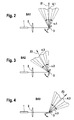
- FIG. 2 explains the operating mode BA1.
- the laser beam is deflected by the deflection mirror 3 at a scanning angle ⁇ 1 about a center position Z1.
- a pulse power P1 a distance range 4.1 is reached.
- FIG. 3 explains the operating mode BA2.
- the laser beam is deflected by the deflection mirror 3 at a scanning angle ⁇ 2 about a center position Z2.
- a pulse power P2 a distance range of 4.2 is achieved.
- FIG. 4 explains the operating mode BA3.
- the laser beam is deflected by the deflection mirror 3 at a scanning angle ⁇ 3 about a center position Z3.
- a pulse power P3 a distance range 4.3 is reached.
- the center layers Z1, Z2, Z3 are usually different.
- the pulse powers P1, P2, P3 and the scan angles ⁇ 1, ⁇ 2, ⁇ 3 can also be the same size in all operating modes or, depending on the particular application, also different.
- MEMS micro-electro-mechanical system
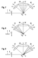
- a plan view of a mirror system 60 with such a deflection mirror 3 with deflection device and holding device in chip structure is shown in FIG. 6 shown.
- the holding device consists of a frame 61 which has a central recess. In the recess, two comb structures 62a, 62b are arranged, by means of which the deflecting mirror 3 is mounted in the frame 61 at least in a rotatable manner, but in particular is capable of oscillating in two dimensions.
- a deflection of the deflection mirror 3 is effected by applying an AC voltage to the comb structures 62a, 62b.
- the size of the scan angle ⁇ 1, ⁇ 2, ⁇ 3 is determined essentially by the magnitude of the applied voltage.
- the center layers Z1, Z2, Z3 are advantageously selected by an additionally applied to the comb structures 62a, 62b DC voltage (offset voltage).
- a suitable voltage curve is, for example, in FIG. 5 shown.
- the driver assistance system can be achieved by additionally introduced into the beam path of the laser imager 10.3 optical components, such as lenses, a desired beam shaping of the vehicle surrounding scanning laser beam.
- optical components such as lenses
- a desired beam shaping of the vehicle surrounding scanning laser beam Exemplary embodiments are described below with reference to FIG FIG. 7, FIG. 8 and FIG. 9 described.
- lenses L1, L2, L3 are provided, wherein the lens L1 of the center layer Z1, the lens L2 of the center layer Z2 and the lens L3 of the center layer Z3 is assigned.
- the scanning mirror is biased by an applied offset voltage such that it is aligned in the center position Z2.
- the deflected by the deflecting mirror 3 laser beam is thus influenced by the lens 2.
- the operating modes can be essentially characterized by the following operating parameters: pulse power of the laser, center position of the deflection mirror, scan angle, rate of change of the scan angle.
- pulse power of the laser For reasons of simplification, the description predominantly always refers only to a one-dimensional deflection of the deflection mirror 3. Analogous considerations also apply in each case to a multi-dimensional, in particular two-dimensional, deflection of the deflection mirror 3.
- a first operating mode BA1 ( FIG. 2 ), which could also be referred to as a "normal" operating mode, the zero position of the deflection mirror 3 is aligned in the direction of the center position Z1.
- the deflection mirror 3 is deflected by the scan angle ⁇ 1 about the zero position.
- a pulse power P1 of the laser 1 With a pulse power P1 of the laser 1, a distance range 4.1 is achieved.
- the scan angle can be varied within design constraints to a larger or smaller field of view cover.
- the pulse power of the laser 1 can be varied to achieve a smaller or larger distance range.
- the zero position of the deflection mirror can be aligned in the center position Z2 or Z3.
- the scan angles ⁇ 2, ⁇ 3 can match the scan angle ⁇ 1 or deviate therefrom.
- the pulse power of the laser 1 can also coincide with the pulse power of the laser 1 in the operating mode BA1 or deviate from it.
- the size of the scan angle is limited by design. As a result, the field of view of the laser imager 10.3 which can be covered in a specific center position of the deflection mirror is also limited.
- the deflection mirror 3 according to operating mode BA2, first brought into the center position Z2 by means of a corresponding offset voltage.
- the field of view achievable with the scan angle ⁇ 2 is scanned with the flying-spot method.
- the image data obtained by reflection on objects are buffered.
- the deflection mirror, according to operating mode BA1 is brought into the center position Z1.
- the field of view achievable with the scan angle ⁇ 1 is scanned with the flying spot method.
- the acquired image data is again stored temporarily.
- a third step by changing the offset voltage, the deflection mirror 3, corresponding to operating mode BA3, is transferred to the center position Z3.
- the field of view achievable with the scan angle ⁇ 3 is scanned with the flying spot method.
- the image data obtained in this third step are combined with the image data obtained in step 1 and step 2 and initially buffered.
- This operating mode BA4 allows a very wide field of view to be detected, which results practically from the sum of the scan angles.
- the operating mode BA4 is particularly suitable for an assistance function, which assists the driver during a parking operation or when entering a cramped access area. Due to the very wide field of view, obstacles can still be detected well in the side area of the vehicle.
- an offset voltage to the deflection mirror 3 can also be functionally effected. If, for example, the laser imager 10.3 is used in the context of an assistance function with pre-crash detection during a high-speed drive, then a restricted viewing angle, for example corresponding to the operating mode BA1, is sufficient FIG. 2 , out. If the driver subsequently wishes to perform a maneuver at low speed or, for example, parking, then obstacles in the lateral area of the vehicle may become important. The deflection mirror 3 of the laser imager 10.3 can then, by applying a suitable offset voltage, according to the modes BA2 and BA3 in the off FIG. 3 respectively. FIG. 4 apparent position.
- a further functional extension can take place in that in the sequentially controlled fields of view, according to the in FIG. 7, FIG. 8 and FIG. 9 illustrated embodiments, optical elements, in particular lenses L1, L2, L3 are introduced for the beam shaping.
- optical properties of the lenses L1, L2, L3 may advantageously be different. For example, such that by means of the lenses L1 and L3 focusing in the near range and by means of the lens L2 focusing in the far range.
- the operating mode BA1, BA2, BA3, BA4 to be assigned to an assistance function AF1, AF2, AF3 can be defined as part of an application and stored in a memory device SP1.
- the memory device SP1 can also be a component of the driver assistance system 10.
- BE additional operating device BE, which enables the driver, if necessary, to manually select the operating mode BA1, BA2, BA3, BA4 that seems suitable for him.
- operating modes of the laser imager 10.3 can also be selected as a function of operating parameters of the vehicle, in particular its speed.
- the mode BA1 FIG. 2
- the deflection mirror 3 of the laser imager 10.3 occupies the center position Z1 and is deflected in the range of the scan angle ⁇ 1.
- Particularly advantageous modes of operation can also be selected depending on the traffic situation.
- an operating mode which is characterized by a high sampling rate, in which therefore the angular range of the scan angle is traversed quickly. As a result, rapid changes in the traffic situation can be detected promptly.
Landscapes
- Physics & Mathematics (AREA)
- Engineering & Computer Science (AREA)
- General Physics & Mathematics (AREA)
- Electromagnetism (AREA)
- Computer Networks & Wireless Communication (AREA)
- Radar, Positioning & Navigation (AREA)
- Remote Sensing (AREA)
- Optics & Photonics (AREA)
- Optical Radar Systems And Details Thereof (AREA)
- Traffic Control Systems (AREA)
Applications Claiming Priority (1)
| Application Number | Priority Date | Filing Date | Title |
|---|---|---|---|
| DE102009000008A DE102009000008A1 (de) | 2009-01-02 | 2009-01-02 | Fahrerassistenzsystem und Verfahren für dessen Steuerung |
Publications (3)
| Publication Number | Publication Date |
|---|---|
| EP2204672A2 true EP2204672A2 (fr) | 2010-07-07 |
| EP2204672A3 EP2204672A3 (fr) | 2010-12-22 |
| EP2204672B1 EP2204672B1 (fr) | 2012-05-30 |
Family
ID=41600328
Family Applications (1)
| Application Number | Title | Priority Date | Filing Date |
|---|---|---|---|
| EP09174970A Active EP2204672B1 (fr) | 2009-01-02 | 2009-11-04 | Système d'assistance du conducteur et son procédé de commande |
Country Status (2)
| Country | Link |
|---|---|
| EP (1) | EP2204672B1 (fr) |
| DE (1) | DE102009000008A1 (fr) |
Cited By (1)
| Publication number | Priority date | Publication date | Assignee | Title |
|---|---|---|---|---|
| WO2023118650A1 (fr) * | 2021-12-22 | 2023-06-29 | Teknologian Tutkimuskeskus Vtt Oy | Module et dispositif de balayage optique améliorés |
Families Citing this family (5)
| Publication number | Priority date | Publication date | Assignee | Title |
|---|---|---|---|---|
| DE102010020814B4 (de) | 2010-05-18 | 2018-05-03 | Thielenhaus Technologies Gmbh | Werkzeughalter zur Finishbearbeitung von Kugellaufbahnen in einer Spindelmutter für einen Kugelgewindetrieb |
| DE102013219567A1 (de) | 2013-09-27 | 2015-04-02 | Robert Bosch Gmbh | Verfahren zur Steuerung eines Mikrospiegelscanners und Mikrospiegelscanner |
| DE102014118054A1 (de) * | 2014-12-08 | 2016-06-09 | Valeo Schalter Und Sensoren Gmbh | Verfahren und Vorrichtung zum Erfassen von Objekten für ein Kraftfahrzeug |
| DE102015109160A1 (de) | 2015-06-10 | 2016-12-15 | Valeo Schalter Und Sensoren Gmbh | Fahrerassistenzsystem für ein Kraftfahrzeug, Kraftfahrzeug sowie Verfahren |
| DE102018102962A1 (de) * | 2018-02-09 | 2019-08-14 | Blickfeld GmbH | Ausrichten eines resonanten Scansystems |
Citations (4)
| Publication number | Priority date | Publication date | Assignee | Title |
|---|---|---|---|---|
| EP1249379A2 (fr) | 2001-04-09 | 2002-10-16 | DaimlerChrysler AG | Méthode et dispositif pour placer un véhicule automobile face à une position ciblée |
| DE10147443A1 (de) | 2001-09-26 | 2003-04-17 | Bosch Gmbh Robert | Umfeldüberwachungsvorrichtung |
| EP1792775A2 (fr) | 2005-12-02 | 2007-06-06 | Volkswagen Aktiengesellschaft | Véhicule et capteur pour détecter des obstacles dans le voisinage du véhicule |
| DE102006026370A1 (de) | 2006-06-07 | 2007-12-13 | Volkswagen Ag | Fahrzeug mit einem Fahrerassistenzsystem |
Family Cites Families (3)
| Publication number | Priority date | Publication date | Assignee | Title |
|---|---|---|---|---|
| DE10007501A1 (de) * | 2000-02-18 | 2001-09-13 | Daimler Chrysler Ag | Verfahren und Vorrichtung zur Erfassung und Überwachung einer Mehrzahl von vorausfahrenden Fahrzeugen |
| JP4830470B2 (ja) | 2005-12-02 | 2011-12-07 | セイコーエプソン株式会社 | 光走査装置、画像形成装置 |
| WO2008154736A1 (fr) * | 2007-06-18 | 2008-12-24 | Leddartech Inc. | Système d'éclairage à fonctions d'assistance au conducteur |
-
2009
- 2009-01-02 DE DE102009000008A patent/DE102009000008A1/de not_active Withdrawn
- 2009-11-04 EP EP09174970A patent/EP2204672B1/fr active Active
Patent Citations (4)
| Publication number | Priority date | Publication date | Assignee | Title |
|---|---|---|---|---|
| EP1249379A2 (fr) | 2001-04-09 | 2002-10-16 | DaimlerChrysler AG | Méthode et dispositif pour placer un véhicule automobile face à une position ciblée |
| DE10147443A1 (de) | 2001-09-26 | 2003-04-17 | Bosch Gmbh Robert | Umfeldüberwachungsvorrichtung |
| EP1792775A2 (fr) | 2005-12-02 | 2007-06-06 | Volkswagen Aktiengesellschaft | Véhicule et capteur pour détecter des obstacles dans le voisinage du véhicule |
| DE102006026370A1 (de) | 2006-06-07 | 2007-12-13 | Volkswagen Ag | Fahrzeug mit einem Fahrerassistenzsystem |
Cited By (1)
| Publication number | Priority date | Publication date | Assignee | Title |
|---|---|---|---|---|
| WO2023118650A1 (fr) * | 2021-12-22 | 2023-06-29 | Teknologian Tutkimuskeskus Vtt Oy | Module et dispositif de balayage optique améliorés |
Also Published As
| Publication number | Publication date |
|---|---|
| DE102009000008A1 (de) | 2010-07-08 |
| EP2204672A3 (fr) | 2010-12-22 |
| EP2204672B1 (fr) | 2012-05-30 |
Similar Documents
| Publication | Publication Date | Title |
|---|---|---|
| EP3593169B1 (fr) | Système lidar ayant des paramètres de balayage flexibles | |
| EP2883748B1 (fr) | Procédé d'affichage d'informations optiques dans des véhicules | |
| EP2204672B1 (fr) | Système d'assistance du conducteur et son procédé de commande | |
| DE10131196A1 (de) | Vorrichtung zur Detektion von Gegenständen, Personen oder dergleichen | |
| EP0464263A2 (fr) | Dispositif de reconnaissance d'obstacles pour des pilotes d'engins volant à basse altitude | |
| EP1395853A1 (fr) | Dispositif de mesure optique de distances | |
| EP1407293A1 (fr) | Procede et dispositif d'acquisition | |
| EP3673289B1 (fr) | Ensemble optique pour système lidar, système lidar et dispositif de travail | |
| EP2433837A1 (fr) | Instrument optique et procédé destiné à la surveillance optique des alentours de véhicules à progression lente | |
| DE102008061760A1 (de) | Vorrichtung zur Überwachung einer Umgebung eines Fahrzeugs | |
| EP2184616B1 (fr) | Procédé et dispositif destinés à la commande d'une source de rayonnement | |
| DE102019125684A1 (de) | Optoelektronischer Sensor und Verfahren zur Erfassung von Objekten | |
| DE102017207493A1 (de) | Senderoptik für ein LiDAR-System, LiDAR-System und Arbeitsvorrichtung | |
| DE102017212384A1 (de) | Ablenkeinrichtung für einen Laserstrahl | |
| DE102021111949A1 (de) | Vorrichtung zur scannenden Messung des Abstands zu einem Objekt | |
| EP3519858B1 (fr) | Unité de balayage d'un dispositif de réception et d'émission optique d'un dispositif de détection optique d'un véhicule | |
| DE102018204708A1 (de) | Makroskopische Lidar-Vorrichtung | |
| EP3628964B1 (fr) | Système de manipulation opto-électromécanique de faisceaux | |
| EP1830572B1 (fr) | Système vidéo frontal suivant les courbes | |
| DE102019218220A1 (de) | LIDAR-Sensor und Verfahren zur optischen Erfassung eines Sichtfeldes | |
| EP4327121A1 (fr) | Dispositif de déviation de signal pour dévier des faisceaux de signaux électromagnétiques d'un appareil de détection, appareil de détection, véhicule comprenant au moins un appareil de détection et procédé pour faire fonctionner un dispositif de déviation de signal | |
| DE102020112311B3 (de) | Kraftfahrzeug mit einem optischen Umgebungssensor und Verfahren zum Betrieb eines Kraftfahrzeugs | |
| DE102018004662A1 (de) | Optisches Erfassungssystem mit variablem Charakteristik-Bereich via dynamischer "Pixelselektion" - gesteuert mit von Systemen zugeführten Steuerungsparameter und/oder gesteuert mittels eigenermittelten Steuerungsparameter | |
| DE102010039255A1 (de) | Optisches System | |
| DE102013107816A1 (de) | Ultraschallvorrichtung und Verfahren zum Betreiben einer Ultraschallvorrichtung |
Legal Events
| Date | Code | Title | Description |
|---|---|---|---|
| PUAI | Public reference made under article 153(3) epc to a published international application that has entered the european phase |
Free format text: ORIGINAL CODE: 0009012 |
|
| AK | Designated contracting states |
Kind code of ref document: A2 Designated state(s): AT BE BG CH CY CZ DE DK EE ES FI FR GB GR HR HU IE IS IT LI LT LU LV MC MK MT NL NO PL PT RO SE SI SK SM TR |
|
| AX | Request for extension of the european patent |
Extension state: AL BA RS |
|
| PUAL | Search report despatched |
Free format text: ORIGINAL CODE: 0009013 |
|
| AK | Designated contracting states |
Kind code of ref document: A3 Designated state(s): AT BE BG CH CY CZ DE DK EE ES FI FR GB GR HR HU IE IS IT LI LT LU LV MC MK MT NL NO PL PT RO SE SI SK SM TR |
|
| AX | Request for extension of the european patent |
Extension state: AL BA RS |
|
| RIC1 | Information provided on ipc code assigned before grant |
Ipc: B60W 30/06 20060101ALN20100205BHEP Ipc: B60W 30/16 20060101ALN20100205BHEP Ipc: G01S 17/93 20060101ALI20101116BHEP Ipc: B60W 30/08 20060101ALN20100205BHEP Ipc: B60W 10/00 20060101ALI20101116BHEP Ipc: B60W 50/08 20060101ALI20101116BHEP Ipc: G01S 13/93 20060101AFI20100205BHEP |
|
| 17P | Request for examination filed |
Effective date: 20110622 |
|
| RIC1 | Information provided on ipc code assigned before grant |
Ipc: B60W 10/00 20060101ALI20120119BHEP Ipc: B60W 30/08 20120101ALN20120119BHEP Ipc: B60W 30/06 20060101ALN20120119BHEP Ipc: G01S 13/93 20060101AFI20120119BHEP Ipc: B60W 30/16 20120101ALN20120119BHEP Ipc: B60W 50/08 20120101ALI20120119BHEP Ipc: G01S 17/93 20060101ALI20120119BHEP |
|
| GRAP | Despatch of communication of intention to grant a patent |
Free format text: ORIGINAL CODE: EPIDOSNIGR1 |
|
| RIC1 | Information provided on ipc code assigned before grant |
Ipc: G01S 13/93 20060101AFI20120224BHEP Ipc: B60W 30/06 20060101ALN20120224BHEP Ipc: B60W 30/08 20120101ALN20120224BHEP Ipc: B60W 50/08 20120101ALI20120224BHEP Ipc: G01S 17/93 20060101ALI20120224BHEP Ipc: B60W 10/00 20060101ALI20120224BHEP Ipc: B60W 30/16 20120101ALN20120224BHEP |
|
| GRAS | Grant fee paid |
Free format text: ORIGINAL CODE: EPIDOSNIGR3 |
|
| GRAA | (expected) grant |
Free format text: ORIGINAL CODE: 0009210 |
|
| AK | Designated contracting states |
Kind code of ref document: B1 Designated state(s): AT BE BG CH CY CZ DE DK EE ES FI FR GB GR HR HU IE IS IT LI LT LU LV MC MK MT NL NO PL PT RO SE SI SK SM TR |
|
| REG | Reference to a national code |
Ref country code: GB Ref legal event code: FG4D Free format text: NOT ENGLISH |
|
| REG | Reference to a national code |
Ref country code: CH Ref legal event code: EP |
|
| REG | Reference to a national code |
Ref country code: AT Ref legal event code: REF Ref document number: 560306 Country of ref document: AT Kind code of ref document: T Effective date: 20120615 |
|
| REG | Reference to a national code |
Ref country code: IE Ref legal event code: FG4D Free format text: LANGUAGE OF EP DOCUMENT: GERMAN |
|
| REG | Reference to a national code |
Ref country code: DE Ref legal event code: R096 Ref document number: 502009003669 Country of ref document: DE Effective date: 20120719 |
|
| REG | Reference to a national code |
Ref country code: NL Ref legal event code: VDEP Effective date: 20120530 |
|
| REG | Reference to a national code |
Ref country code: LT Ref legal event code: MG4D Effective date: 20120523 |
|
| PG25 | Lapsed in a contracting state [announced via postgrant information from national office to epo] |
Ref country code: LT Free format text: LAPSE BECAUSE OF FAILURE TO SUBMIT A TRANSLATION OF THE DESCRIPTION OR TO PAY THE FEE WITHIN THE PRESCRIBED TIME-LIMIT Effective date: 20120530 Ref country code: SE Free format text: LAPSE BECAUSE OF FAILURE TO SUBMIT A TRANSLATION OF THE DESCRIPTION OR TO PAY THE FEE WITHIN THE PRESCRIBED TIME-LIMIT Effective date: 20120530 Ref country code: FI Free format text: LAPSE BECAUSE OF FAILURE TO SUBMIT A TRANSLATION OF THE DESCRIPTION OR TO PAY THE FEE WITHIN THE PRESCRIBED TIME-LIMIT Effective date: 20120530 Ref country code: IS Free format text: LAPSE BECAUSE OF FAILURE TO SUBMIT A TRANSLATION OF THE DESCRIPTION OR TO PAY THE FEE WITHIN THE PRESCRIBED TIME-LIMIT Effective date: 20120930 Ref country code: CY Free format text: LAPSE BECAUSE OF FAILURE TO SUBMIT A TRANSLATION OF THE DESCRIPTION OR TO PAY THE FEE WITHIN THE PRESCRIBED TIME-LIMIT Effective date: 20120530 Ref country code: NO Free format text: LAPSE BECAUSE OF FAILURE TO SUBMIT A TRANSLATION OF THE DESCRIPTION OR TO PAY THE FEE WITHIN THE PRESCRIBED TIME-LIMIT Effective date: 20120830 |
|
| PG25 | Lapsed in a contracting state [announced via postgrant information from national office to epo] |
Ref country code: LV Free format text: LAPSE BECAUSE OF FAILURE TO SUBMIT A TRANSLATION OF THE DESCRIPTION OR TO PAY THE FEE WITHIN THE PRESCRIBED TIME-LIMIT Effective date: 20120530 Ref country code: SI Free format text: LAPSE BECAUSE OF FAILURE TO SUBMIT A TRANSLATION OF THE DESCRIPTION OR TO PAY THE FEE WITHIN THE PRESCRIBED TIME-LIMIT Effective date: 20120530 Ref country code: GR Free format text: LAPSE BECAUSE OF FAILURE TO SUBMIT A TRANSLATION OF THE DESCRIPTION OR TO PAY THE FEE WITHIN THE PRESCRIBED TIME-LIMIT Effective date: 20120831 Ref country code: HR Free format text: LAPSE BECAUSE OF FAILURE TO SUBMIT A TRANSLATION OF THE DESCRIPTION OR TO PAY THE FEE WITHIN THE PRESCRIBED TIME-LIMIT Effective date: 20120530 |
|
| PG25 | Lapsed in a contracting state [announced via postgrant information from national office to epo] |
Ref country code: SK Free format text: LAPSE BECAUSE OF FAILURE TO SUBMIT A TRANSLATION OF THE DESCRIPTION OR TO PAY THE FEE WITHIN THE PRESCRIBED TIME-LIMIT Effective date: 20120530 Ref country code: EE Free format text: LAPSE BECAUSE OF FAILURE TO SUBMIT A TRANSLATION OF THE DESCRIPTION OR TO PAY THE FEE WITHIN THE PRESCRIBED TIME-LIMIT Effective date: 20120530 Ref country code: CZ Free format text: LAPSE BECAUSE OF FAILURE TO SUBMIT A TRANSLATION OF THE DESCRIPTION OR TO PAY THE FEE WITHIN THE PRESCRIBED TIME-LIMIT Effective date: 20120530 Ref country code: DK Free format text: LAPSE BECAUSE OF FAILURE TO SUBMIT A TRANSLATION OF THE DESCRIPTION OR TO PAY THE FEE WITHIN THE PRESCRIBED TIME-LIMIT Effective date: 20120530 Ref country code: RO Free format text: LAPSE BECAUSE OF FAILURE TO SUBMIT A TRANSLATION OF THE DESCRIPTION OR TO PAY THE FEE WITHIN THE PRESCRIBED TIME-LIMIT Effective date: 20120530 Ref country code: NL Free format text: LAPSE BECAUSE OF FAILURE TO SUBMIT A TRANSLATION OF THE DESCRIPTION OR TO PAY THE FEE WITHIN THE PRESCRIBED TIME-LIMIT Effective date: 20120530 |
|
| PG25 | Lapsed in a contracting state [announced via postgrant information from national office to epo] |
Ref country code: PT Free format text: LAPSE BECAUSE OF FAILURE TO SUBMIT A TRANSLATION OF THE DESCRIPTION OR TO PAY THE FEE WITHIN THE PRESCRIBED TIME-LIMIT Effective date: 20121001 Ref country code: IT Free format text: LAPSE BECAUSE OF FAILURE TO SUBMIT A TRANSLATION OF THE DESCRIPTION OR TO PAY THE FEE WITHIN THE PRESCRIBED TIME-LIMIT Effective date: 20120530 Ref country code: PL Free format text: LAPSE BECAUSE OF FAILURE TO SUBMIT A TRANSLATION OF THE DESCRIPTION OR TO PAY THE FEE WITHIN THE PRESCRIBED TIME-LIMIT Effective date: 20120530 |
|
| PLBE | No opposition filed within time limit |
Free format text: ORIGINAL CODE: 0009261 |
|
| STAA | Information on the status of an ep patent application or granted ep patent |
Free format text: STATUS: NO OPPOSITION FILED WITHIN TIME LIMIT |
|
| PG25 | Lapsed in a contracting state [announced via postgrant information from national office to epo] |
Ref country code: ES Free format text: LAPSE BECAUSE OF FAILURE TO SUBMIT A TRANSLATION OF THE DESCRIPTION OR TO PAY THE FEE WITHIN THE PRESCRIBED TIME-LIMIT Effective date: 20120910 |
|
| 26N | No opposition filed |
Effective date: 20130301 |
|
| BERE | Be: lapsed |
Owner name: ROBERT BOSCH G.M.B.H. Effective date: 20121130 |
|
| REG | Reference to a national code |
Ref country code: DE Ref legal event code: R097 Ref document number: 502009003669 Country of ref document: DE Effective date: 20130301 |
|
| PG25 | Lapsed in a contracting state [announced via postgrant information from national office to epo] |
Ref country code: BG Free format text: LAPSE BECAUSE OF FAILURE TO SUBMIT A TRANSLATION OF THE DESCRIPTION OR TO PAY THE FEE WITHIN THE PRESCRIBED TIME-LIMIT Effective date: 20120830 |
|
| REG | Reference to a national code |
Ref country code: IE Ref legal event code: MM4A |
|
| PG25 | Lapsed in a contracting state [announced via postgrant information from national office to epo] |
Ref country code: BE Free format text: LAPSE BECAUSE OF NON-PAYMENT OF DUE FEES Effective date: 20121130 |
|
| PG25 | Lapsed in a contracting state [announced via postgrant information from national office to epo] |
Ref country code: IE Free format text: LAPSE BECAUSE OF NON-PAYMENT OF DUE FEES Effective date: 20121104 |
|
| PG25 | Lapsed in a contracting state [announced via postgrant information from national office to epo] |
Ref country code: MT Free format text: LAPSE BECAUSE OF FAILURE TO SUBMIT A TRANSLATION OF THE DESCRIPTION OR TO PAY THE FEE WITHIN THE PRESCRIBED TIME-LIMIT Effective date: 20120530 |
|
| PG25 | Lapsed in a contracting state [announced via postgrant information from national office to epo] |
Ref country code: TR Free format text: LAPSE BECAUSE OF FAILURE TO SUBMIT A TRANSLATION OF THE DESCRIPTION OR TO PAY THE FEE WITHIN THE PRESCRIBED TIME-LIMIT Effective date: 20120530 Ref country code: MC Free format text: LAPSE BECAUSE OF NON-PAYMENT OF DUE FEES Effective date: 20121130 |
|
| PG25 | Lapsed in a contracting state [announced via postgrant information from national office to epo] |
Ref country code: LU Free format text: LAPSE BECAUSE OF NON-PAYMENT OF DUE FEES Effective date: 20121104 Ref country code: SM Free format text: LAPSE BECAUSE OF FAILURE TO SUBMIT A TRANSLATION OF THE DESCRIPTION OR TO PAY THE FEE WITHIN THE PRESCRIBED TIME-LIMIT Effective date: 20120530 |
|
| REG | Reference to a national code |
Ref country code: CH Ref legal event code: PL |
|
| PG25 | Lapsed in a contracting state [announced via postgrant information from national office to epo] |
Ref country code: CH Free format text: LAPSE BECAUSE OF NON-PAYMENT OF DUE FEES Effective date: 20131130 Ref country code: LI Free format text: LAPSE BECAUSE OF NON-PAYMENT OF DUE FEES Effective date: 20131130 Ref country code: HU Free format text: LAPSE BECAUSE OF FAILURE TO SUBMIT A TRANSLATION OF THE DESCRIPTION OR TO PAY THE FEE WITHIN THE PRESCRIBED TIME-LIMIT Effective date: 20091104 |
|
| PG25 | Lapsed in a contracting state [announced via postgrant information from national office to epo] |
Ref country code: MK Free format text: LAPSE BECAUSE OF FAILURE TO SUBMIT A TRANSLATION OF THE DESCRIPTION OR TO PAY THE FEE WITHIN THE PRESCRIBED TIME-LIMIT Effective date: 20120530 |
|
| REG | Reference to a national code |
Ref country code: FR Ref legal event code: PLFP Year of fee payment: 7 |
|
| REG | Reference to a national code |
Ref country code: AT Ref legal event code: MM01 Ref document number: 560306 Country of ref document: AT Kind code of ref document: T Effective date: 20141104 |
|
| PG25 | Lapsed in a contracting state [announced via postgrant information from national office to epo] |
Ref country code: AT Free format text: LAPSE BECAUSE OF NON-PAYMENT OF DUE FEES Effective date: 20141104 |
|
| REG | Reference to a national code |
Ref country code: FR Ref legal event code: PLFP Year of fee payment: 8 |
|
| REG | Reference to a national code |
Ref country code: FR Ref legal event code: PLFP Year of fee payment: 9 |
|
| PGFP | Annual fee paid to national office [announced via postgrant information from national office to epo] |
Ref country code: GB Payment date: 20191126 Year of fee payment: 11 |
|
| GBPC | Gb: european patent ceased through non-payment of renewal fee |
Effective date: 20201104 |
|
| PG25 | Lapsed in a contracting state [announced via postgrant information from national office to epo] |
Ref country code: GB Free format text: LAPSE BECAUSE OF NON-PAYMENT OF DUE FEES Effective date: 20201104 |
|
| REG | Reference to a national code |
Ref country code: DE Ref legal event code: R084 Ref document number: 502009003669 Country of ref document: DE |
|
| PGFP | Annual fee paid to national office [announced via postgrant information from national office to epo] |
Ref country code: FR Payment date: 20231124 Year of fee payment: 15 |
|
| PG25 | Lapsed in a contracting state [announced via postgrant information from national office to epo] |
Ref country code: FR Free format text: LAPSE BECAUSE OF NON-PAYMENT OF DUE FEES Effective date: 20241130 |
|
| PGFP | Annual fee paid to national office [announced via postgrant information from national office to epo] |
Ref country code: DE Payment date: 20260126 Year of fee payment: 17 |