EP2204784B1 - System und Verfahren zur Überwachung des Wachsamkeitszustands des Fahrers eines Fahrzeugs - Google Patents
System und Verfahren zur Überwachung des Wachsamkeitszustands des Fahrers eines Fahrzeugs Download PDFInfo
- Publication number
- EP2204784B1 EP2204784B1 EP08425825A EP08425825A EP2204784B1 EP 2204784 B1 EP2204784 B1 EP 2204784B1 EP 08425825 A EP08425825 A EP 08425825A EP 08425825 A EP08425825 A EP 08425825A EP 2204784 B1 EP2204784 B1 EP 2204784B1
- Authority
- EP
- European Patent Office
- Prior art keywords
- driver
- vehicle
- travel
- steering
- state
- Prior art date
- Legal status (The legal status is an assumption and is not a legal conclusion. Google has not performed a legal analysis and makes no representation as to the accuracy of the status listed.)
- Active
Links
Images





Classifications
-
- G—PHYSICS
- G08—SIGNALLING
- G08B—SIGNALLING SYSTEMS, e.g. PERSONAL CALLING SYSTEMS; ORDER TELEGRAPHS; ALARM SYSTEMS
- G08B21/00—Alarms responsive to a single specified undesired or abnormal condition and not otherwise provided for
- G08B21/02—Alarms for ensuring the safety of persons
- G08B21/06—Alarms for ensuring the safety of persons indicating a condition of sleep, e.g. anti-dozing alarms
-
- B—PERFORMING OPERATIONS; TRANSPORTING
- B60—VEHICLES IN GENERAL
- B60K—ARRANGEMENT OR MOUNTING OF PROPULSION UNITS OR OF TRANSMISSIONS IN VEHICLES; ARRANGEMENT OR MOUNTING OF PLURAL DIVERSE PRIME-MOVERS IN VEHICLES; AUXILIARY DRIVES FOR VEHICLES; INSTRUMENTATION OR DASHBOARDS FOR VEHICLES; ARRANGEMENTS IN CONNECTION WITH COOLING, AIR INTAKE, GAS EXHAUST OR FUEL SUPPLY OF PROPULSION UNITS IN VEHICLES
- B60K28/00—Safety devices for propulsion-unit control, specially adapted for, or arranged in, vehicles, e.g. preventing fuel supply or ignition in the event of potentially dangerous conditions
- B60K28/02—Safety devices for propulsion-unit control, specially adapted for, or arranged in, vehicles, e.g. preventing fuel supply or ignition in the event of potentially dangerous conditions responsive to conditions relating to the driver
- B60K28/06—Safety devices for propulsion-unit control, specially adapted for, or arranged in, vehicles, e.g. preventing fuel supply or ignition in the event of potentially dangerous conditions responsive to conditions relating to the driver responsive to incapacity of driver
- B60K28/066—Safety devices for propulsion-unit control, specially adapted for, or arranged in, vehicles, e.g. preventing fuel supply or ignition in the event of potentially dangerous conditions responsive to conditions relating to the driver responsive to incapacity of driver actuating a signalling device
-
- B—PERFORMING OPERATIONS; TRANSPORTING
- B60—VEHICLES IN GENERAL
- B60W—CONJOINT CONTROL OF VEHICLE SUB-UNITS OF DIFFERENT TYPE OR DIFFERENT FUNCTION; CONTROL SYSTEMS SPECIALLY ADAPTED FOR HYBRID VEHICLES; ROAD VEHICLE DRIVE CONTROL SYSTEMS FOR PURPOSES NOT RELATED TO THE CONTROL OF A PARTICULAR SUB-UNIT
- B60W2540/00—Input parameters relating to occupants
- B60W2540/18—Steering angle
-
- B—PERFORMING OPERATIONS; TRANSPORTING
- B60—VEHICLES IN GENERAL
- B60W—CONJOINT CONTROL OF VEHICLE SUB-UNITS OF DIFFERENT TYPE OR DIFFERENT FUNCTION; CONTROL SYSTEMS SPECIALLY ADAPTED FOR HYBRID VEHICLES; ROAD VEHICLE DRIVE CONTROL SYSTEMS FOR PURPOSES NOT RELATED TO THE CONTROL OF A PARTICULAR SUB-UNIT
- B60W2540/00—Input parameters relating to occupants
- B60W2540/22—Psychological state; Stress level or workload
-
- B—PERFORMING OPERATIONS; TRANSPORTING
- B60—VEHICLES IN GENERAL
- B60W—CONJOINT CONTROL OF VEHICLE SUB-UNITS OF DIFFERENT TYPE OR DIFFERENT FUNCTION; CONTROL SYSTEMS SPECIALLY ADAPTED FOR HYBRID VEHICLES; ROAD VEHICLE DRIVE CONTROL SYSTEMS FOR PURPOSES NOT RELATED TO THE CONTROL OF A PARTICULAR SUB-UNIT
- B60W2540/00—Input parameters relating to occupants
- B60W2540/221—Physiology, e.g. weight, heartbeat, health or special needs
-
- B—PERFORMING OPERATIONS; TRANSPORTING
- B60—VEHICLES IN GENERAL
- B60W—CONJOINT CONTROL OF VEHICLE SUB-UNITS OF DIFFERENT TYPE OR DIFFERENT FUNCTION; CONTROL SYSTEMS SPECIALLY ADAPTED FOR HYBRID VEHICLES; ROAD VEHICLE DRIVE CONTROL SYSTEMS FOR PURPOSES NOT RELATED TO THE CONTROL OF A PARTICULAR SUB-UNIT
- B60W2556/00—Input parameters relating to data
- B60W2556/45—External transmission of data to or from the vehicle
- B60W2556/50—External transmission of data to or from the vehicle of positioning data, e.g. GPS [Global Positioning System] data
Definitions
- the present invention relates to driving assistance systems, in particular systems for active safety, and more specifically the techniques of monitoring the state of vigilance of the driver of a vehicle.
- the systems which are based on the direct monitoring of the driver are regarded as intrusive passive systems, since they require measuring instruments placed in the passenger compartment, very close to or in contact with the person, and therefore devices visible to the driver or which may alter the driving ambience and which, finally, may form a disturbance for the driver.
- These systems have the advantage of being able to carry out direct measurements on the person and consequently are more reliable compared with other types of systems.
- the systems which are based on the monitoring of entities related to the vehicle system are on the other hand regarded as non-intrusive passive systems, since they do not require cooperation on the part of the driver and the measurements are taken without any disturbance to him.
- they are based on indirect measurements, i.e. they relate to the degree of vigilance of the driver by means of the measurement of parameters external to him, in general vehicle operating parameters.
- the operations of detecting the parameters in question are normally simple, since they use elementary sensors often already present on the vehicle for other functions.
- the principal systems which belong to this category are distinguished between systems which are based on the detection of entities characteristic of the dynamics of the vehicle, such as its position (with respect to the carriageway) and direction of travel, the evolution of the longitudinal and lateral speed, the yaw angle and rate, longitudinal acceleration and deceleration, lateral acceleration, and systems which are based on the evaluation of the driving operations carried out by the driver, such as operation of the pedals, the gear-change or the steering wheel.
- DDDS Driver Drowsy Detection Systems
- DDDS Driver Drowsy Detection Systems
- a processing unit 20 arranged for interpreting the data received according to a programmed logic within it, optionally as a result of the identification of the driver which has been carried out by a system 30 according to an auto-learning logic.
- the processing unit is therefore adapted to supply a signal indicating the estimated psycho-physical conditions of the driver and, if the conditions are not optimal, actuating an alarm or signalling system 40.
- the method used in the systems for monitoring entities associated with the dynamics of the vehicle is generally simple: via predetermined sensors (accelerometers, phonic wheels, odometers, gyroscopes) signals indicative of the entities of interest are obtained directly, or they are calculated on the basis of the entities detected by means of analytical operations: the evolution over time of the signal representing the entity being examined is therefore compared with the evolution of reference signals, generally estimated in an auto-learning step in which, starting from the hypothesis that the driver is vigilant when driving commences, the system determines one or more threshold values; finally, the state of vigilance of the driver is determined according to the result of the comparison.
- sensors accelerometers, phonic wheels, odometers, gyroscopes
- the signal indicating the entity measured exhibits wide fluctuations over time.
- the variables which are most frequently monitored are the angular position of the steering wheel, in particular the amplitude of the corrections made by the driver during driving and the frequency with which such corrections are carried out, the speed of the movements of the steering wheel during the corrections of direction and the torque exerted on the steering wheel by the driver to carry out the manoeuvres.
- the steering wheel angle which makes it possible to pick up and analyse the micro-movements which the driver makes in order to correct the direction of travel.
- the driver constantly seeks to hold the vehicle in the centre of the lane with very frequent actions consisting of small, sometimes imperceptible, corrections of the steering wheel angle, which translate into small corrections of direction of the vehicle.
- the movements for controlling the steering wheel have a maximum amplitude of around 2° in a range of frequency of between 0.1 and 0.3Hz. It is very important to stress that the width of this field does not vary significantly when considering straight or curved routes.
- Figure 2 shows by comparison the signals for correction of the steering wheel angle when the driver is in a rested and a tired state. It is possible to observe visually the difference between the two curves, the upper diagram relating to a driver in good physical condition and the lower diagram relating to the same driver when fatigued.
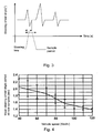
- the first signal indicates the time interval calculated from the moment in which a steering action is executed until the normal direction (rectilinear direction) is returned to; the second signal defines the period between two successive steering manoeuvres.
- the level of vigilance of the driver declines in a manner inversely proportional to the steering peaks recorded. It is consequently possible to state that the time interval between one correction and another represents the discriminating factor between a state of vigilance or otherwise: the more driving fatigue increases, the more the time intervals between successive steering actions increase.
- the frequency and amplitude of the corrections varies from driver to driver, so that, in particular, a less sensitive driver always tends to carry out corrections of direction less frequently and with a greater amplitude, even in a vigilant state.
- Possible solutions to the problem are those of implementing a system capable of rapidly learning the driving style of the driver, or of recognising it among a series of stored profiles.
- a processing unit based on a neural network may be used.
- the period of the corrections on the part of the driver depends on the route followed and the overall travel conditions, including ambient and traffic conditions, and in particular decreases as the speed of travel of the vehicle increases, approximately following the evolution shown in Figure 4 .
- this aim is achieved by means of a system for monitoring the state of vigilance of the driver of a vehicle having the characteristics claimed in claim 1.
- a further subject of the invention is a method for monitoring the state of vigilance of the driver of a vehicle having the characteristics claimed in claim 11.
- the present invention is based on the principle of processing the signal representing the evolution of the steering wheel angle through filtering based on information originating from the cartography and/or digital maps of the route which the vehicle is travelling, and also, subordinately, from signals which indicate voluntary deviations from a direction estimated on the basis of the cartographic data, for example for the execution of overtaking or turning manoeuvres, indicated by the actuation of the direction indicators.
- FIG. 5 A system for monitoring the state of vigilance of a driver, improved according to the teaching of the invention, is depicted in Figure 5 , where elements or components identical or functionally equivalent to those illustrated in Figure 1 have been indicated by the same reference numbers.
- a sensor 10 associated with the steering equipment of the vehicle V is arranged for continuously measuring the steering angle in dependence on the time with respect to a reference zero (travel in a straight line) and for emitting a respective measurement signal S steer .
- Further sensors arranged for detecting the yaw rate are adapted to provide a signal Sy for estimating the rotation of the vehicle with respect to its centre of gravity, integrating the entity measured in the sampling time.
- Auxiliary sensors of a different kind adapted to detect operating states of devices for monitoring the dynamics of the vehicle (ABS, ASR, VDC,...) may also be provided.
- the processing unit 20 is adapted to supply a signal S driver indicating the estimated psycho-physical condition of the driver, as will be described in more detail hereinafter. This is also coupled to an alarm or signalling system 40, that can be actuated on the basis of the value assumed by the signal S driver .
- the signal S steer is the combination of at least two contributions, respectively a first contribution due to the manoeuvres of following a general direction of travel, established by following a specific route which may have straight and curved sections or deviations, or by the existing traffic conditions (hence the need for overtaking or changes of lane), and a second contribution due to the steering correction manoeuvres with respect to the general direction of travel followed.
- the structure of the conventional system shown in Figure 1 is enhanced with a cartographic module 50, arranged for storing digital maps of a geographic region, to which the processing unit 20 is connected for reading.
- the processing unit 20 is further coupled to a geographic positioning module 60, for example a module for satellite positioning of the vehicle according to the GPS system, incorporated into the onboard instrumentation or in any case available via a communications connection, for example a portable navigation apparatus connectable to the infotel network of the vehicle by means of a cable or wireless communications protocol, such as Bluetooth or the like.
- the processing unit of the monitoring system could benefit from the positioning data on digital maps originating from an onboard navigation system, incorporating a GPS positioning device.
- a digital map has the advantage of comprising much more information than a standard map, including, with great accuracy, data of each road route, whether straight or curved, of road junctions, of radii of curvature or local inclination of the roads, besides road sign data.
- the unit 20 is further connected via a CAN network or dedicated lines to onboard devices or instruments 70 including, for example, the direction indicator devices, adapted to signal intentions of voluntary manoeuvring by the driver, the screen cleaning devices, adapted to signal the presence of adverse atmospheric conditions, sensors for the temperature outside the vehicle, of the type arranged for detecting the presence of ice on the road surface, an odometer, adapted to measure the speed of the vehicle.
- the processing unit operates as described below.
- the steering angle signal measured in dependence on the time with respect to a reference zero, is acquired.
- the variation and the oscillation of the angle is the result of the sum of various contributions, among which will be included the reaction force of the roadbed, the disturbances originating from the ambience, the curvature of the lane of travel with respect to the horizontal plane, and finally the action exerted on the steering wheel by the driver.
- the steering signal is processed by means of the use of the PSD (Power Spectral Density) function of auto-correlation of the signal at the time t with that of the signal at the time t+ ⁇ .
- PSD Power Spectral Density
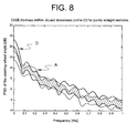
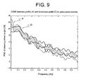
- Figures 6-9 show graphs of the evolution of the PSD curve with intervals of confidence at 95% in the case of alert state and drowsy state of the driver, respectively in route conditions with combined curved and straight sections ( Figure 6 ), with curved sections and with combined curved and straight sections in which the driver is vigilant ( Figure 7 ), with only straight sections ( Figure 8 ) and with only curved sections in the case of a vigilant state and a drowsy state ( Figure 9 ).
- the graph in Figure 6 clearly shows that there is no superposition between the intervals of confidence in a drowsy state (D) and an alert state (A) for the frequencies around 0.45Hz, 0.60Hz and 0.80Hz. At these frequencies a significant difference is therefore established between the PSD curve of the alert state (A) and the PSD curve of the drowsy state (D), which is useful for classification of the state of vigilance of the driver.
- the value of the steering angle measured takes account not only of the micro-corrections, the real subject of the analysis of interest for the estimation of the degree of vigilance of the driver, but also of the value of the steering angle imposed in order to take the bend itself, a value is therefore "added” (constant if the radius of the bend is constant) which must be eliminated before analysing the useful signal, bringing the analysis scenario, virtually, to a state of travel in a straight line.
- the steering angle corresponding to the radius of curvature is determined by the relationship between parameters relating to the dynamics of the vehicle.
- Such a system proves to be insufficiently reliable and accurate, since the determination of the steering angle is in this way independent of the traffic conditions and the morphology of the route travelled.
- the solution to the problem is the use of the data from the cartography, coupled to a GPS sensor; the co-ordinates of the vehicle being known, the road state in which the latter is to be found is established, i.e. whether the vehicle is in a straight travel section or on a bend. From the geometric parameters of the road, including the radius of curvature, and which are objective since they come from cartographic data and are not estimated by onboard sensors, it is possible to "clean up" the steering angle signal in order to render it representative of only the micro-corrections applied by the driver.
- Figure 10 shows the technique for determining the contributions for correction of the steering angle, "cleaned" of the voluntary steering contributions for following curved travel sections. Knowing each time the radius of curvature of the route from the cartographic data, the steering angle corresponding to the radius of curvature is subtracted from the effective steering angle measured.
- a further refinement may be obtained by knowing the state of the direction indicators.
- the processing unit can decide to suspend spectral analysis for a time interval in order to avoid an erroneous interpretation of the state of vigilance of the driver and consequent emission of false alarm signals.
- an external temperature sensor may be used for detecting adverse meteorological conditions and the corresponding influence on the dynamics of the vehicle, so that in such conditions the system of the invention is rendered transparent, or de-activated.
- the signal S steer is filtered, "cleaned" of the curvature of the travel direction at the module 100 and confirmed according to the cartographic data (GPS position of the vehicle, digital maps), to the dynamics of the vehicle (yaw rate, state of actuation of the ABS anti-lock wheel systems, of ASR anti-skid wheel systems, VDC vehicle stability control, for example), to the travel conditions (state of direction indicators for signalling intention of possible overtaking manoeuvres) and to the general meteorological driving conditions (external temperature, state of actuation of the screen cleaning devices).
- the cartographic data GPS position of the vehicle, digital maps
- dynamics of the vehicle yaw rate, state of actuation of the ABS anti-lock wheel systems, of ASR anti-skid wheel systems, VDC vehicle stability control, for example
- travel conditions state of direction indicators for signalling intention of possible overtaking manoeuvres
- general meteorological driving conditions external temperature, state of actuation of the screen cleaning devices.
- the module 100 is therefore adapted to process and transmit downstream a signal indicating the corrective steering contributions applied by the driver with respect to the general direction of travel followed, indicated in the drawings as S corr .
- a subsequent module 110 for calculating the PSD function defined above receives at the input the signal S corr and calculates the value of the PSD curve for the corrective steering contributions applied by the driver.
- the curve representing the corrective steering angle over time and the data obtained therefrom are compared with reference signals or data, for example via neural networks, in order to estimate the degree of vigilance of the driver, specifically in order to discriminate between a degree of vigilance sufficient for safe driving and an insufficient degree of vigilance, so that there are risks of an accident.
- the power spectral density PSD calculated is acquired by a neural network 120 classifying the state of the driver, which is adapted to compare the acquired curve with predetermined frequential profiles of alertness and possible drowsiness.
- the profiles are obtained starting from the standard power spectral density for drowsiness and from that for alertness, in the non-superimposed PSD regions.
- the power spectral density in the vigilant state may derive from training of the neural network 120 dependent on the driving style of the driver on board. He should, therefore, on installation of the aforesaid system, start up a preliminary learning procedure in order to configure the estimation algorithm to his own driving style, for a prefixed learning time in which it is necessary to drive in a fully rested state, without alteration of the actual psycho-physical state (typically related to the ingestion of alcoholic drinks, drugs and medicines), following mixed straight and curved routes, alternating urban and out of town routes, varying the speed so as not to polarise the neural network only for some route conditions.
- the actual psycho-physical state typically related to the ingestion of alcoholic drinks, drugs and medicines
- a module 150 for defining the superimposed and non-superimposed regions of the PSD curves is adapted to train the neural network 120 selectively according to a learning command LEARN given by the driver.
- the input receives the PSD profiles for an alert state and a drowsy state from respective neural networks 160, 170, which are themselves trained by data banks of standard profiles of PSD(f) curves for alertness and drowsiness 200, 210 according to the speed of the vehicle and frequencies of corrections, by means of associated training modules that can be selectively connected by the same LEARN command.
- the PSD alert curve profile is supplied by the same calculation module 110 to the training module of the neural network 160, via a selection controlled by the SEL signal emitted by the timer.
- the drawing shows an operating state in which, in the course of a learning period controlled intentionally by the driver, the timer 300 emits a LEARN signal for a learning command, via which the training modules associated with the neural networks 160, 170 are selectively connected to the respective networks in order to supply to them the PSD curve to be learnt, according to the speed of the vehicle and a sequence of correction frequencies.
- the signal S driver is then supplied, indicating the estimated state of vigilance of the driver.
- the processing unit 20 detects a state of vigilance of the driver below a predetermined alarm threshold, the system intervenes with suitable signalling or alarms to prevent dangerous situations.
- the signalling or alarm systems actuated automatically by the system, can supply stimuli to the driver to wake him or recall him to vigilance by signalling to him the non-optimum physical conditions, to warn surrounding vehicles (V2V, vehicle to vehicle) of the danger or to warn the monitoring infrastructures for the road traffic, for example the police forces or a suitable surveillance entity (V2I, vehicle to infrastructure).
- the measures which can be adopted to awaken the vigilance of the driver comprise stimuli of a visual, acoustic, thermal or physical type:
Landscapes
- Engineering & Computer Science (AREA)
- Business, Economics & Management (AREA)
- Emergency Management (AREA)
- Physics & Mathematics (AREA)
- General Physics & Mathematics (AREA)
- Chemical & Material Sciences (AREA)
- Combustion & Propulsion (AREA)
- Transportation (AREA)
- Mechanical Engineering (AREA)
- Traffic Control Systems (AREA)
- Control Of Driving Devices And Active Controlling Of Vehicle (AREA)
- Auxiliary Drives, Propulsion Controls, And Safety Devices (AREA)
Claims (15)
- System zur Überwachung des Wachsamkeitszustands des Fahrers (D) eines Fahrzeugs (V), das einer allgemeinen Fahrtrichtung entlang einer Route folgt, das aufweist:eine Sensoreinrichtung (10), die angepasst ist, den Lenkwinkel des Fahrzeugs (V) zu detektieren und ein Lenksignal (Ssteer), das die Entwicklung des Winkels über die Zeit repräsentiert, auszusenden; undeine elektronische Verarbeitungseinrichtung (20), die angepasst ist, das Lenksignal (Ssteer) von der Sensoreinrichtung (10) zu empfangen, und eingerichtet ist für:das Filtern des Lenksignals (Ssteer), um daraus die Lenkanteile, die dadurch bedingt sind, dass einer allgemeinen Fahrtrichtung gefolgt wird, zu eliminieren,das Durchführen eines Vergleichs der detektierten Kenngrößen der Korrekturmanöver mit zuvor bestimmten Bezugskenngrößen; unddas Bewerten des Wachsamkeitszustands des Fahrers (D) entsprechend dem Ergebnis jenes Vergleichs,wobei die Verarbeitungseinrichtung (20) für das Erfassen kartographischer Daten, das Berechnen der allgemeinen Fahrtrichtung des Fahrzeugs (V) zum Folgen der Route auf der Basis der kartographischen Daten und das Abschätzen, aufgrund dieser Daten, der Lenkanteile, die dadurch bedingt sind, dass jener Richtung gefolgt wird, eingerichtet ist,dadurch gekennzeichnet, dass die Verarbeitungseinrichtung (20) eingerichtet ist für das Erfassen kartographischer Daten, welche die vom Fahrzeug (V) befahrene Straßenroute anzeigen, und für das Filtern des Lenksignals (Ssteer), um ein gefiltertes Signal (Scorr) zu erhalten, das die Kenngrößen von Amplitude und Frequenz der Lenkkorrekturmanöver in Bezug auf die allgemeine Fahrtrichtung, der gefolgt wird, anzeigt.
- System gemäß Anspruch 1, bei dem zu den zuvor bestimmten Bezugskenngrößen Schwellenwerte für Amplitude und Frequenz der Korrekturmanöver gehören, die entsprechend der Fahrgeschwindigkeit des Fahrzeugs (V) bekannt sind.
- System gemäß Anspruch 1, bei dem zu den zuvor bestimmten Bezugskenngrößen Schwellenwerte für Amplitude und Frequenz der Korrekturmanöver gehören, die durch das Erlernen des Fahrverhaltens des Fahrers (D) erhalten werden.
- System gemäß einem der vorangegangenen Ansprüche, bei dem die Verarbeitungseinrichtung (20) für das Durchführen einer Spektralanalyse der Korrekturmanöver durch Vergleich zwischen einer Kurve der spektralen Leistungsdichte PSD für eine Autokorrelation des detektierten Lenksignals und Kurven der zuvor bestimmten spektralen Leistungsdichte PSD für eine Autokorrelation des Lenksignals, jeweils verbunden mit Zuständen der Wachheit (A) und der Schläfrigkeit (D) des Fahrers, bei den bekannten Frequenzen der Nichtüberlagerung eingerichtet ist.
- System gemäß Anspruch 4, bei dem die Verarbeitungseinrichtung (20) für das Erfassen von Daten, welche die Fahrabsichten repräsentieren, aus Richtungsanzeigevorrichtungen und das Erkennen der Kenngrößen von Amplitude und Frequenz des Lenksignals in Verbindung mit absichtlichen Manövern zum Ändern der Fahrtrichtung eingerichtet ist.
- System gemäß Anspruch 5, bei dem die Verarbeitungseinrichtung (20) für das Unterbrechen der Spektralanalyse für eine zuvor bestimmte Zeitdauer eingerichtet ist, um eine Fehlinterpretation des Wachsamkeitszustands des Fahrers (D) beim Erkennen absichtlicher Manöver zum Ändern der Fahrtrichtung zu vermeiden.
- System gemäß Anspruch 4, bei dem die Verarbeitungseinrichtung (20) für das Erfassen von Daten, die zu der Gruppe von Daten gehören, welche die Außentemperatur, den Betätigungszustand der Reinigungsvorrichtungen der Windschutzscheibe, den Betätigungszustand der Antiblockiersysteme ABS, von Systemen zur Antriebsschlupfregelung ASR, von Systemen zur dynamischen Fahrzeugstabilitätskontrolle VDC anzeigen, und für das Erkennen widriger Wetterbedingungen und des entsprechenden Einflusses auf die Dynamik des Fahrzeugs (V) eingerichtet ist.
- System gemäß Anspruch 7, bei dem die Verarbeitungseinrichtung (20) für das Unterbrechen der Spektralanalyse für eine zuvor bestimmte Zeitdauer eingerichtet ist, um eine Fehlinterpretation des Wachsamkeitszustands des Fahrers (D) beim Erkennen widriger Wetterbedingungen zu vermeiden.
- System gemäß einem der vorangegangenen Ansprüche, bei dem zu den kartographischen Daten digitale Landkarten (50) einer geographischen Region gehören, die aus Vorrichtungen erfasst werden können, die vorübergehend mit dem System verbunden sind oder dauerhaft zu ihm gehören, und bei dem die Verarbeitungseinrichtung (20) mit einer Einrichtung (60) zum Bestimmen der geographischen Position des Fahrzeugs gekoppelt ist.
- System gemäß einem der vorangegangenen Ansprüche, bei dem die Verarbeitungseinrichtung (20) für das Aussenden von Signalen oder Alarmen eingerichtet ist, welche angepasst sind, dem Fahrer (D) Reize zuzuführen, und Fahrzeuge in der Umgebung warnen und die Infrastrukturen zur Überwachung des Straßenverkehrs warnen, wenn ein Wachsamkeitszustand des Fahrers (D) unter einer zuvor bestimmten Alarmschwelle detektiert wird.
- Verfahren zur Überwachung des Wachsamkeitszustands des Fahrers (D) eines Fahrzeugs (V), das einer allgemeinen Fahrtrichtung entlang einer Route folgt, das aufweist:Detektieren des Lenkwinkels des Fahrzeugs und Aussenden eines Lenksignals (Ssteer), das die Entwicklung des Winkels über die Zeit repräsentiert;Erfassen kartographischer Daten und Berechnen der allgemeinen Fahrtrichtung des Fahrzeugs zum Folgen der Route auf der Basis der kartographischen Daten;Abschätzen, aufgrund dieser Daten, der Lenkanteile, die dadurch bedingt sind, dass jener Richtung gefolgt wird;Filtern des Lenksignals (Ssteer), um daraus die Lenkanteile, die dadurch bedingt sind, dass einer allgemeinen Fahrtrichtung gefolgt wird, zu eliminieren;Durchführen des Vergleichs der Kenngrößen der detektierten Korrekturmanöver mit zuvor bestimmten Bezugsgrößen; undBewerten des Wachsamkeitszustands des Fahrers (D) entsprechend dem Ergebnis jenes Vergleichs,wobei das Verfahren dadurch gekennzeichnet ist, dass es kartographische Daten erfasst, welche die vom Fahrzeug (V) befahrene Straßenroute anzeigen, und dass es das Lenksignal (Ssteer) filtert, um ein gefiltertes Signal (scorr) zu erhalten, das die Kenngrößen von Amplitude und Frequenz der Lenkkorrekturmanöver in Bezug auf die allgemeine Fahrtrichtung, der gefolgt wird, anzeigt.
- Verfahren gemäß Anspruch 11, mit der Erfassung zuvor bestimmter Bezugskenngrößen, zu denen Schwellenwerte für Amplitude und Frequenz der Korrekturmanöver gehören, die entsprechend der Fahrgeschwindigkeit des Fahrzeugs (V) bekannt sind.
- Verfahren gemäß Anspruch 11, mit der Erfassung zuvor bestimmter Bezugskenngrößen, zu denen Schwellenwerte für Amplitude und Frequenz der Korrekturmanöver gehören, die durch das Erlernen des Fahrverhaltens des Fahrers (D) erhalten werden.
- Verfahren gemäß einem der Ansprüche 11 bis 13, mit einer Spektralanalyse der Korrekturmanöver, zu der ein Vergleich zwischen einer Kurve der spektralen Leistungsdichte PSD für eine Autokorrelation des detektierten Lenksignals und Kurven der zuvor bestimmten spektralen Leistungsdichte PSD für eine Autokorrelation des Lenksignals, jeweils verbunden mit Zuständen der Wachheit (A) und der Schläfrigkeit (D) des Fahrers, bei den bekannten Frequenzen der Nichtüberlagerung gehört.
- Verfahren gemäß Anspruch 14, mit der Erfassung von Daten, welche die Fahrabsichten repräsentieren, aus Richtungsanzeigevorrichtungen, der Erkennung von Kenngrößen von Amplitude und Frequenz des Lenksignals, die mit absichtlichen Manövern zum Ändern der Fahrtrichtung verbunden sind, und der Unterbrechung der Spektralanalyse für eine zuvor bestimmte Zeitdauer, um eine Fehlinterpretation des Wachsamkeitszustands des Fahrers (D) beim Erkennen absichtlicher Manöver zum Ändern der Fahrtrichtung zu vermeiden.
Priority Applications (2)
| Application Number | Priority Date | Filing Date | Title |
|---|---|---|---|
| AT08425825T ATE524801T1 (de) | 2008-12-31 | 2008-12-31 | System und verfahren zur überwachung des wachsamkeitszustands des fahrers eines fahrzeugs |
| EP08425825A EP2204784B1 (de) | 2008-12-31 | 2008-12-31 | System und Verfahren zur Überwachung des Wachsamkeitszustands des Fahrers eines Fahrzeugs |
Applications Claiming Priority (1)
| Application Number | Priority Date | Filing Date | Title |
|---|---|---|---|
| EP08425825A EP2204784B1 (de) | 2008-12-31 | 2008-12-31 | System und Verfahren zur Überwachung des Wachsamkeitszustands des Fahrers eines Fahrzeugs |
Publications (2)
| Publication Number | Publication Date |
|---|---|
| EP2204784A1 EP2204784A1 (de) | 2010-07-07 |
| EP2204784B1 true EP2204784B1 (de) | 2011-09-14 |
Family
ID=40637935
Family Applications (1)
| Application Number | Title | Priority Date | Filing Date |
|---|---|---|---|
| EP08425825A Active EP2204784B1 (de) | 2008-12-31 | 2008-12-31 | System und Verfahren zur Überwachung des Wachsamkeitszustands des Fahrers eines Fahrzeugs |
Country Status (2)
| Country | Link |
|---|---|
| EP (1) | EP2204784B1 (de) |
| AT (1) | ATE524801T1 (de) |
Cited By (1)
| Publication number | Priority date | Publication date | Assignee | Title |
|---|---|---|---|---|
| RU2648541C1 (ru) * | 2016-12-12 | 2018-03-26 | Сергей Васильевич Бродягин | Устройство для предупреждения засыпания водителя транспортного средства во время движения |
Families Citing this family (5)
| Publication number | Priority date | Publication date | Assignee | Title |
|---|---|---|---|---|
| US9663047B2 (en) * | 2012-02-01 | 2017-05-30 | Fico Mirrors, S.A. | Method and system for inferring the behavior or state of the driver of a vehicle, use of the method and computer program for carrying out the method |
| DE102017210966A1 (de) * | 2017-06-28 | 2019-01-03 | Volkswagen Aktiengesellschaft | Verfahren und Vorrichtung zum Betreiben eines Kraftfahrzeugs mit einem Lenksystem für die Identifikation von Fahrereingriffen |
| US10227039B1 (en) * | 2018-02-19 | 2019-03-12 | Delphi Technologies, Llc | Warning system |
| CN109448377B (zh) * | 2018-11-29 | 2020-07-28 | 交通运输部公路科学研究所 | 一种使用卫星定位数据进行车辆行驶安全性评价的方法 |
| DE102020124910A1 (de) | 2020-09-24 | 2022-03-24 | Bayerische Motoren Werke Aktiengesellschaft | Verfahren zum Unterstützen eines Fahrers beim manuellen Führen eines Kraftfahrzeugs, Unterstützungseinrichtung und Kraftfahrzeug |
Family Cites Families (4)
| Publication number | Priority date | Publication date | Assignee | Title |
|---|---|---|---|---|
| US6061610A (en) * | 1997-10-31 | 2000-05-09 | Nissan Technical Center North America, Inc. | Method and apparatus for determining workload of motor vehicle driver |
| EP1695310B1 (de) * | 2003-11-30 | 2008-09-03 | Volvo Technology Corporation | Verfahren und system zum erkennen einer fahrerbeeinträchtigung |
| JP2008146515A (ja) * | 2006-12-13 | 2008-06-26 | Hitachi Ltd | 疲労度検出装置,自動車の制御装置および制御方法 |
| DE102006060849A1 (de) * | 2006-12-22 | 2008-07-03 | Daimler Ag | Verfahren zur Ermittlung eines Fahrerzustands |
-
2008
- 2008-12-31 AT AT08425825T patent/ATE524801T1/de not_active IP Right Cessation
- 2008-12-31 EP EP08425825A patent/EP2204784B1/de active Active
Cited By (1)
| Publication number | Priority date | Publication date | Assignee | Title |
|---|---|---|---|---|
| RU2648541C1 (ru) * | 2016-12-12 | 2018-03-26 | Сергей Васильевич Бродягин | Устройство для предупреждения засыпания водителя транспортного средства во время движения |
Also Published As
| Publication number | Publication date |
|---|---|
| EP2204784A1 (de) | 2010-07-07 |
| ATE524801T1 (de) | 2011-09-15 |
Similar Documents
| Publication | Publication Date | Title |
|---|---|---|
| JP7324716B2 (ja) | 情報処理装置、移動装置、および方法、並びにプログラム | |
| JP4595377B2 (ja) | 運転者状態検出装置及びプログラム | |
| CN107200022B (zh) | 驾驶辅助系统和方法 | |
| KR102469467B1 (ko) | 차량 안전 지원 장치 및 방법 | |
| CN107336710B (zh) | 驾驶意识推定装置 | |
| JP4711826B2 (ja) | 運転者の障害を認識するための方法およびシステム | |
| CN102274031B (zh) | 异常操作检测方法和异常操作检测系统 | |
| JP4396597B2 (ja) | 危険反応地点記録システム及び運転支援システム | |
| EP1997705B1 (de) | Fahrverhaltenschätzungsvorrichtung, fahrunterstützungsvorrichtung, fahrzeugbewertungssystem, vorrichtung zur herstellung eines fahrermodells und vorrichtung zur beurteilung des fahrverhaltens | |
| JP5158677B2 (ja) | ドライバ特性検出装置 | |
| JP4803490B2 (ja) | 運転者状態推定装置及び運転支援装置 | |
| CN108394414A (zh) | 清醒度判定系统以及清醒度判定方法 | |
| CN105072986A (zh) | 驾驶支援装置、驾驶支援方法、信息提供装置、信息提供方法、导航装置以及导航方法 | |
| EP2204784A1 (de) | System und Verfahren zur Überwachung des Wachsamkeitszustands des Fahrers eines Fahrzeugs | |
| CN105564436A (zh) | 一种高级驾驶辅助系统 | |
| JP2007122579A (ja) | 車両制御装置 | |
| KR20130039203A (ko) | 차량 위치 정보 기반 비정상 운전 판정 및 경보 시스템 | |
| JP2011242190A (ja) | 運転支援装置 | |
| JP7222887B2 (ja) | 車両制御システム、車両制御方法、およびプログラム | |
| CN102762149A (zh) | 用于确定警觉状态的装置和方法 | |
| SE529656C2 (sv) | Metod och system för övervakning av manuell styrning av dynamiska system | |
| TW201441080A (zh) | 疲勞駕駛監測系統與方法 | |
| JP2004149035A (ja) | 車両用追従走行制御装置 | |
| JP3393463B2 (ja) | 車両運転状態検出装置 | |
| JP2010102538A (ja) | 居眠り判定装置 |
Legal Events
| Date | Code | Title | Description |
|---|---|---|---|
| PUAI | Public reference made under article 153(3) epc to a published international application that has entered the european phase |
Free format text: ORIGINAL CODE: 0009012 |
|
| AK | Designated contracting states |
Kind code of ref document: A1 Designated state(s): AT BE BG CH CY CZ DE DK EE ES FI FR GB GR HR HU IE IS IT LI LT LU LV MC MT NL NO PL PT RO SE SI SK TR |
|
| AX | Request for extension of the european patent |
Extension state: AL BA MK RS |
|
| GRAP | Despatch of communication of intention to grant a patent |
Free format text: ORIGINAL CODE: EPIDOSNIGR1 |
|
| 17P | Request for examination filed |
Effective date: 20110105 |
|
| AKX | Designation fees paid |
Designated state(s): AT BE BG CH CY CZ DE DK EE ES FI FR GB GR HR HU IE IS IT LI LT LU LV MC MT NL NO PL PT RO SE SI SK TR |
|
| GRAS | Grant fee paid |
Free format text: ORIGINAL CODE: EPIDOSNIGR3 |
|
| RAP1 | Party data changed (applicant data changed or rights of an application transferred) |
Owner name: MAGNETI MARELLI S.P.A. |
|
| GRAA | (expected) grant |
Free format text: ORIGINAL CODE: 0009210 |
|
| AK | Designated contracting states |
Kind code of ref document: B1 Designated state(s): AT BE BG CH CY CZ DE DK EE ES FI FR GB GR HR HU IE IS IT LI LT LU LV MC MT NL NO PL PT RO SE SI SK TR |
|
| REG | Reference to a national code |
Ref country code: GB Ref legal event code: FG4D |
|
| REG | Reference to a national code |
Ref country code: CH Ref legal event code: EP |
|
| REG | Reference to a national code |
Ref country code: IE Ref legal event code: FG4D |
|
| REG | Reference to a national code |
Ref country code: DE Ref legal event code: R096 Ref document number: 602008009775 Country of ref document: DE Effective date: 20111117 |
|
| REG | Reference to a national code |
Ref country code: NL Ref legal event code: VDEP Effective date: 20110914 |
|
| PG25 | Lapsed in a contracting state [announced via postgrant information from national office to epo] |
Ref country code: LT Free format text: LAPSE BECAUSE OF FAILURE TO SUBMIT A TRANSLATION OF THE DESCRIPTION OR TO PAY THE FEE WITHIN THE PRESCRIBED TIME-LIMIT Effective date: 20110914 Ref country code: HR Free format text: LAPSE BECAUSE OF FAILURE TO SUBMIT A TRANSLATION OF THE DESCRIPTION OR TO PAY THE FEE WITHIN THE PRESCRIBED TIME-LIMIT Effective date: 20110914 Ref country code: SE Free format text: LAPSE BECAUSE OF FAILURE TO SUBMIT A TRANSLATION OF THE DESCRIPTION OR TO PAY THE FEE WITHIN THE PRESCRIBED TIME-LIMIT Effective date: 20110914 Ref country code: NO Free format text: LAPSE BECAUSE OF FAILURE TO SUBMIT A TRANSLATION OF THE DESCRIPTION OR TO PAY THE FEE WITHIN THE PRESCRIBED TIME-LIMIT Effective date: 20111214 Ref country code: FI Free format text: LAPSE BECAUSE OF FAILURE TO SUBMIT A TRANSLATION OF THE DESCRIPTION OR TO PAY THE FEE WITHIN THE PRESCRIBED TIME-LIMIT Effective date: 20110914 |
|
| LTIE | Lt: invalidation of european patent or patent extension |
Effective date: 20110914 |
|
| PG25 | Lapsed in a contracting state [announced via postgrant information from national office to epo] |
Ref country code: GR Free format text: LAPSE BECAUSE OF FAILURE TO SUBMIT A TRANSLATION OF THE DESCRIPTION OR TO PAY THE FEE WITHIN THE PRESCRIBED TIME-LIMIT Effective date: 20111215 Ref country code: LV Free format text: LAPSE BECAUSE OF FAILURE TO SUBMIT A TRANSLATION OF THE DESCRIPTION OR TO PAY THE FEE WITHIN THE PRESCRIBED TIME-LIMIT Effective date: 20110914 Ref country code: CY Free format text: LAPSE BECAUSE OF FAILURE TO SUBMIT A TRANSLATION OF THE DESCRIPTION OR TO PAY THE FEE WITHIN THE PRESCRIBED TIME-LIMIT Effective date: 20110914 Ref country code: SI Free format text: LAPSE BECAUSE OF FAILURE TO SUBMIT A TRANSLATION OF THE DESCRIPTION OR TO PAY THE FEE WITHIN THE PRESCRIBED TIME-LIMIT Effective date: 20110914 Ref country code: AT Free format text: LAPSE BECAUSE OF FAILURE TO SUBMIT A TRANSLATION OF THE DESCRIPTION OR TO PAY THE FEE WITHIN THE PRESCRIBED TIME-LIMIT Effective date: 20110914 |
|
| REG | Reference to a national code |
Ref country code: AT Ref legal event code: MK05 Ref document number: 524801 Country of ref document: AT Kind code of ref document: T Effective date: 20110914 |
|
| PG25 | Lapsed in a contracting state [announced via postgrant information from national office to epo] |
Ref country code: BE Free format text: LAPSE BECAUSE OF FAILURE TO SUBMIT A TRANSLATION OF THE DESCRIPTION OR TO PAY THE FEE WITHIN THE PRESCRIBED TIME-LIMIT Effective date: 20110914 |
|
| PG25 | Lapsed in a contracting state [announced via postgrant information from national office to epo] |
Ref country code: CZ Free format text: LAPSE BECAUSE OF FAILURE TO SUBMIT A TRANSLATION OF THE DESCRIPTION OR TO PAY THE FEE WITHIN THE PRESCRIBED TIME-LIMIT Effective date: 20110914 Ref country code: IS Free format text: LAPSE BECAUSE OF FAILURE TO SUBMIT A TRANSLATION OF THE DESCRIPTION OR TO PAY THE FEE WITHIN THE PRESCRIBED TIME-LIMIT Effective date: 20120114 Ref country code: SK Free format text: LAPSE BECAUSE OF FAILURE TO SUBMIT A TRANSLATION OF THE DESCRIPTION OR TO PAY THE FEE WITHIN THE PRESCRIBED TIME-LIMIT Effective date: 20110914 |
|
| PG25 | Lapsed in a contracting state [announced via postgrant information from national office to epo] |
Ref country code: RO Free format text: LAPSE BECAUSE OF FAILURE TO SUBMIT A TRANSLATION OF THE DESCRIPTION OR TO PAY THE FEE WITHIN THE PRESCRIBED TIME-LIMIT Effective date: 20110914 Ref country code: PL Free format text: LAPSE BECAUSE OF FAILURE TO SUBMIT A TRANSLATION OF THE DESCRIPTION OR TO PAY THE FEE WITHIN THE PRESCRIBED TIME-LIMIT Effective date: 20110914 Ref country code: NL Free format text: LAPSE BECAUSE OF FAILURE TO SUBMIT A TRANSLATION OF THE DESCRIPTION OR TO PAY THE FEE WITHIN THE PRESCRIBED TIME-LIMIT Effective date: 20110914 Ref country code: EE Free format text: LAPSE BECAUSE OF FAILURE TO SUBMIT A TRANSLATION OF THE DESCRIPTION OR TO PAY THE FEE WITHIN THE PRESCRIBED TIME-LIMIT Effective date: 20110914 Ref country code: PT Free format text: LAPSE BECAUSE OF FAILURE TO SUBMIT A TRANSLATION OF THE DESCRIPTION OR TO PAY THE FEE WITHIN THE PRESCRIBED TIME-LIMIT Effective date: 20120116 |
|
| PLBE | No opposition filed within time limit |
Free format text: ORIGINAL CODE: 0009261 |
|
| STAA | Information on the status of an ep patent application or granted ep patent |
Free format text: STATUS: NO OPPOSITION FILED WITHIN TIME LIMIT |
|
| PG25 | Lapsed in a contracting state [announced via postgrant information from national office to epo] |
Ref country code: MC Free format text: LAPSE BECAUSE OF NON-PAYMENT OF DUE FEES Effective date: 20111231 Ref country code: DK Free format text: LAPSE BECAUSE OF FAILURE TO SUBMIT A TRANSLATION OF THE DESCRIPTION OR TO PAY THE FEE WITHIN THE PRESCRIBED TIME-LIMIT Effective date: 20110914 |
|
| 26N | No opposition filed |
Effective date: 20120615 |
|
| REG | Reference to a national code |
Ref country code: IE Ref legal event code: MM4A |
|
| REG | Reference to a national code |
Ref country code: DE Ref legal event code: R097 Ref document number: 602008009775 Country of ref document: DE Effective date: 20120615 |
|
| PG25 | Lapsed in a contracting state [announced via postgrant information from national office to epo] |
Ref country code: IE Free format text: LAPSE BECAUSE OF NON-PAYMENT OF DUE FEES Effective date: 20111231 |
|
| PG25 | Lapsed in a contracting state [announced via postgrant information from national office to epo] |
Ref country code: MT Free format text: LAPSE BECAUSE OF FAILURE TO SUBMIT A TRANSLATION OF THE DESCRIPTION OR TO PAY THE FEE WITHIN THE PRESCRIBED TIME-LIMIT Effective date: 20110914 |
|
| PG25 | Lapsed in a contracting state [announced via postgrant information from national office to epo] |
Ref country code: LU Free format text: LAPSE BECAUSE OF NON-PAYMENT OF DUE FEES Effective date: 20111231 |
|
| PG25 | Lapsed in a contracting state [announced via postgrant information from national office to epo] |
Ref country code: BG Free format text: LAPSE BECAUSE OF FAILURE TO SUBMIT A TRANSLATION OF THE DESCRIPTION OR TO PAY THE FEE WITHIN THE PRESCRIBED TIME-LIMIT Effective date: 20111214 |
|
| REG | Reference to a national code |
Ref country code: CH Ref legal event code: PL |
|
| GBPC | Gb: european patent ceased through non-payment of renewal fee |
Effective date: 20121231 |
|
| PG25 | Lapsed in a contracting state [announced via postgrant information from national office to epo] |
Ref country code: ES Free format text: LAPSE BECAUSE OF FAILURE TO SUBMIT A TRANSLATION OF THE DESCRIPTION OR TO PAY THE FEE WITHIN THE PRESCRIBED TIME-LIMIT Effective date: 20111225 Ref country code: HU Free format text: LAPSE BECAUSE OF FAILURE TO SUBMIT A TRANSLATION OF THE DESCRIPTION OR TO PAY THE FEE WITHIN THE PRESCRIBED TIME-LIMIT Effective date: 20110914 Ref country code: LI Free format text: LAPSE BECAUSE OF NON-PAYMENT OF DUE FEES Effective date: 20121231 Ref country code: CH Free format text: LAPSE BECAUSE OF NON-PAYMENT OF DUE FEES Effective date: 20121231 |
|
| PG25 | Lapsed in a contracting state [announced via postgrant information from national office to epo] |
Ref country code: GB Free format text: LAPSE BECAUSE OF NON-PAYMENT OF DUE FEES Effective date: 20121231 |
|
| REG | Reference to a national code |
Ref country code: FR Ref legal event code: PLFP Year of fee payment: 8 |
|
| REG | Reference to a national code |
Ref country code: FR Ref legal event code: PLFP Year of fee payment: 9 |
|
| REG | Reference to a national code |
Ref country code: FR Ref legal event code: PLFP Year of fee payment: 10 |
|
| PGFP | Annual fee paid to national office [announced via postgrant information from national office to epo] |
Ref country code: DE Payment date: 20241121 Year of fee payment: 17 |
|
| PGFP | Annual fee paid to national office [announced via postgrant information from national office to epo] |
Ref country code: FR Payment date: 20241121 Year of fee payment: 17 |
|
| PGFP | Annual fee paid to national office [announced via postgrant information from national office to epo] |
Ref country code: TR Payment date: 20241127 Year of fee payment: 17 |
|
| PGFP | Annual fee paid to national office [announced via postgrant information from national office to epo] |
Ref country code: IT Payment date: 20241121 Year of fee payment: 17 |