EP2204829B1 - Commutation marche/arrêt - Google Patents
Commutation marche/arrêt Download PDFInfo
- Publication number
- EP2204829B1 EP2204829B1 EP20090150121 EP09150121A EP2204829B1 EP 2204829 B1 EP2204829 B1 EP 2204829B1 EP 20090150121 EP20090150121 EP 20090150121 EP 09150121 A EP09150121 A EP 09150121A EP 2204829 B1 EP2204829 B1 EP 2204829B1
- Authority
- EP
- European Patent Office
- Prior art keywords
- rod member
- cylindrical member
- end portion
- light
- state
- Prior art date
- Legal status (The legal status is an assumption and is not a legal conclusion. Google has not performed a legal analysis and makes no representation as to the accuracy of the status listed.)
- Active
Links
Images


Classifications
-
- H—ELECTRICITY
- H01—ELECTRIC ELEMENTS
- H01H—ELECTRIC SWITCHES; RELAYS; SELECTORS; EMERGENCY PROTECTIVE DEVICES
- H01H23/00—Tumbler or rocker switches, i.e. switches characterised by being operated by rocking an operating member in the form of a rocker button
- H01H23/02—Details
- H01H23/12—Movable parts; Contacts mounted thereon
- H01H23/14—Tumblers
- H01H23/146—Tumblers having a generally tubular or conical elongated shape, e.g. dolly
-
- H—ELECTRICITY
- H01—ELECTRIC ELEMENTS
- H01H—ELECTRIC SWITCHES; RELAYS; SELECTORS; EMERGENCY PROTECTIVE DEVICES
- H01H3/00—Mechanisms for operating contacts
- H01H3/32—Driving mechanisms, i.e. for transmitting driving force to the contacts
- H01H3/38—Driving mechanisms, i.e. for transmitting driving force to the contacts using spring or other flexible shaft coupling
-
- H—ELECTRICITY
- H03—ELECTRONIC CIRCUITRY
- H03K—PULSE TECHNIQUE
- H03K17/00—Electronic switching or gating, i.e. not by contact-making and –breaking
- H03K17/94—Electronic switching or gating, i.e. not by contact-making and –breaking characterised by the way in which the control signals are generated
- H03K17/965—Switches controlled by moving an element forming part of the switch
- H03K17/968—Switches controlled by moving an element forming part of the switch using opto-electronic devices
Definitions
- the present invention relates to an ON/OFF switch which performs switching operation between two predetermined actions, such as lighting and extinction, or start and stop of an action apparatus.
- ON/OFF switches As a device for performing switching operation between two predetermined actions such as lighting and extinction, or start and stop of an action apparatus, ON/OFF switches are widely used.
- an ON/OFF switch a device utilizing a contacting state of an electrically conductive member and a separated state thereof to conduct electrical connection to a circuit and electrical disconnection from the circuit (hereinafter, called "contact switch") is widely used and it is variously modified to various aspects suitable for use situations.
- JPA-2006-294574 proposes a simple contact switch with a simple structure which can cause a switch lever to have high operability.
- the simple contact switch uses a coil spring at a fulcrum portion of the switch lever, thereby allowing simplification of a structure of the lever switch with excellent operability, whose distal end can be inclined in an arbitrary direction in a whole circumferential direction (360°).
- the contact switch includes such a problem as contact failure or wiring complexity in multi-functional configuration. Therefore, in order to solve such a problem, there is such a trial as adoption of a non-contact structure instead of a structure where an electrically conductive member in the contact switch causes mechanical contact.
- a non-contact type switch there is a combination switch for a vehicle utilizing optical signal means, which is disclosed in JPA-11-306925 .
- the combination switch for a vehicle is configured to perform action switching by blocking light arriving from a light emitting element to a light receiving element via a light guide plate using a slider sliding in response to movement of a lever switch to change a light amount arriving the light receiving element. That is, since the structure for sliding a slider for blocking a light path is adopted instead of the structure for causing mechanical contact, a problem attached to the contact switch can be solved.
- the combination switch for a vehicle is intended to perform switching in a plurality of sets of two actions utilizing one lever, the structure thereof is still complicated. Therefore, when simpler and lower cost structure including only one set of actions as a target to be switched is required, such a combination switch is improper.
- a movable range of individual lever switches is limited to one plane, where one lever cannot be tilted in an arbitrary direction in a whole circumferential direction.
- a cylindrical member having flexibility and being stretchable so as to be freely restored to a normal state is fixed to a base member
- a rod member having flexibility is inserted into the cylindrical member and is supported by a guide maintaining a state of an axial line of the rod member to the cylindrical member regardless of the state of the cylindrical member
- one end of the rod member is fixed to an end portion of the cylindrical member which is not fixed to the base member and the other end thereof is protruded from the cylindrical member
- a surrounding portion surrounding the end portion of the rod member which is protruded from the cylindrical member in a non-contact manner is provided.
- a converting unit converting movement of the end portion of the rod member protruded from the cylindrical member relative to the surrounding portion to electrical signal binary to output the same.
- the electrical signal binary means so-called "1" or "0" signal may also be a signal indicating whether or not a predetermined voltage is obtained at an output terminal, or the like.
- the predetermined voltage can be set to an optimal value according to use situation, for example, 5V ⁇ 1V or 24V ⁇ 2V can be adopted.
- the term "state of an axial line of the rod member to the cylindrical member” may be thought as a relative positional relationship of the axial line of the rod member to an axial line of the cylindrical member.
- the term “maintaining a state of an axial line of the rod member to the cylindrical member” means, for example, that, when a rod member is inserted into a cylindrical member coaxially, the axial line of the rod member is caused to coincide with the axial line of the cylindrical member and that when the rod member is inserted into the cylindrical member such that an axial line of the former becomes parallel to an axial line of the latter, both the axial lines are kept parallel to each other.
- a state that an end portion of the rod member has been surrounded by a surrounding portion means a state that the surrounding member is disposed over a region including at least half of a length of the rod member in a outer peripheral direction thereof, where a length of the rod member in an axial direction thereof is not limited.
- such a definition is made that even when a plate member with U shape in plan view having a thickness of about 1mm is applied to an end portion of a rod member with an entire length of about 10cm as the surrounding portion, a thickness direction of the plate member is made parallel to the axial direction of the rod member, and the rod member is disposed such that it is inserted into a recessed portion of the plate member, the end portion of the rodmember is surrounded by the surrounding portion.
- the surrounding portion may have a peripheral wall continuing in an entire peripheral direction.
- the surrounding portion is arranged over a whole area of an outer circumferential direction of the rod member.
- the end portion of the rod member is surrounded by the surrounding portion.
- the surrounding portion may be longer than a movement region of an end portion of the rod member protruded from the cylindrical member in the axial line direction of the rod member.
- a portion of a distal end portion of the rod member reaching a certain length thereof is accommodated in the surrounding portion, so that the end portion of the rod member is surrounded in the surrounding portion.
- the surrounding portion when the surroundingportion is configured so as to continue in the entire peripheral direction, the surrounding portion forms a cylindrical member.
- the converting means may be provided with a light emitting element and a light receiving element, and it may be configured to perform conversion to the electrical signal binary utilizing according to presence and absence of light arriving from the light emitting element to the light receiving element.
- the light emitting element and the light receiving element may be arranged so as to maintain a positional relationship where a light path from the light emitting element to the light receiving element intersects a moving route of the end portion of the rod member protruded from the cylindrical member, or they may be arranged so as to maintain a positional relationship where light from the light emitting element is reflected by an end face of the end portion of the rod member protruded from the cylindrical member at the predetermined position to reach the light receiving element.
- the end portion of the rod member protruded from the cylindrical member may include a permeability member attached to the rod member, and the converting means may be provided with a coil surrounding the permeability member in a normal state and an oscillation circuit connected to the coil to perform conversion to the electrical signal binary utilizing presence and absence of induced electromotive force.
- the end portion of the rod member protruded from the cylindrical member may include a magnetic body attached to the rod member, and the converting means may be provided with a magnetic force sensor to perform conversion to the electrical signal binary utilizing strong and weak of magnetic force detected by the magnetic force sensor.
- bending force which is similarly applied to the rod member
- free end which is similarly applied to the rod member
- proximal end an end portion of the cylindrical member fixed to the base member
- movement of the moving end portion of the rod member is converted to movement along the original axial line of the moving end portion of the rod member regardless of a direction in which the free end is bent, which results in specific movement to the surrounding portion surrounding the moving end portion in a non-contacting manner.
- movement of the moving end portion relative to the surrounding portion to electrical signal binary to be outputted and causing two values of the binary to correspond to two predetermined actions, switching operation between these two actions can be performed.
- conversion to electrical signal binary may be performed utilizing presence and absence of light arriving from the light emitting element to the light receiving element.
- the light emitting element and the light receiving element are disposed in a positional relationship where a light path arriving from the light emitting element to the light receiving element intersects a moving route of the moving end portion of the rod member, when the light path is blocked by the rod member, light from the light emitting element does not reach the light receiving element, so that conversion to electrical signal binary can be performed utilizing presence and absence of light arriving from the light emitting element to the light receiving element.
- the light emitting element and the light receiving element are disposed in a positional relationship where light from the light emitting element is reflected by an end face of the moving end portion at the predetermined position to reach the light receiving element, when the rod member moves and a relative position between the light emitting element and the light receiving element changes, light from the light emitting element does not reach the light receiving element, so that conversion to electrical signal binary can be performed utilizing presence and absence of light arriving from the light emitting element to the light receiving element.
- the converting means When a permeability member is attached to the rod member, the converting means may be provided with a coil surrounding the permeability member in an ordinary state and an oscillation circuit connected to the coil. In this case, when the rod member moves so that the permeability member moves to a position where it is out of the coil, induced electromotive force becomes weak so that conversion to electrical signal binary can be performed utilizing strong and weak of the induced electromotive force.
- the converting means may be provided with a magnetic force sensor.
- the rod member moves so that the relative distance between the magnetic body and the magnetic force sensor changes, magnetic force detected by the magnetic force sensor changes, so that conversion to electrical signal binary can be performed utilizing strong and weak of the magnetic force.
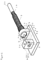
- FIG. 1 is a perspective view showing an appearance of a main constituent portion of an ON/OFF switch according to the embodiment of the present invention.
- FIGs. 2A and 2B are vertical sectional views for explaining an operation principle of the ON/OFF switch according to the embodiment, FIG. 2A showing an ordinary state and FIG. 2B showing a state that bending force has been applied to a free end.
- FIGs. 3A and 3B are vertical sectional views for explaining an operation principle of converting means or unit of the ON/OFF switch according to the embodiment, FIG. 3A showing an ordinary state and FIG. 3B showing a state that bending force has been applied to the free end.
- Main constituent elements of the ON/OFF switch comprises a cylindrical member 1, a rod member 2, a base member 3, a guide 4, a surrounding portion 5, and converting means 6.
- a known coil spring is adopted as the cylindrical member 1, one end 1a (proximal end) of the cylindrical member is fixed to a base member 3 via a fixing member 11 fitted and fixed on an outer periphery of the one end 1a, and a rod member 2 is inserted into the cylindrical member 1.
- material thereof or the like is not limited to specific one. Proper material can be selected for the cylindrical member 1 in response to a use situation or the like.
- the rod member 2 is inserted into the cylindrical member 1 and it is supported by a guide 4.
- One end 2b of the rod member 2 is fixed to an end portion 1b (free end) of the cylindrical member 1 which is not fixed to the base member 3, and the other end 2a thereof is protruded from the cylindrical member 1.
- An end portion 2c (moving end portion) of the rod member 2 protruded from the cylindrical member 1 is surrounded by a surrounding portion 5 provided on the base member 3 in a non-contacting state.
- the rod member 2 is configured by molding synthetic resin and shaping the resin to a shape suitable for the ON/OFF switch, but since any material having flexibility and required strength can be used as the rod member 2, material to be used for the rod member 2 is not limited to a specific one. Proper material can be selected for the rod member 2 in response to a use situation or the like.
- the guide 4 comprises a disk-like member, it is provided at its center with an insertion hole 4a for the rod member 2, and it is fitted in an opening of the proximal end 1a of the cylindrical member 1.
- the insertion hole 4a has an opening diameter slightly larger than an axis diameter of the rod member 2 such that sliding of the rod member 2 is allowed, but movement of the rod member 2 in a direction perpendicular to the axial line of the rod member 2 is restricted. Therefore, a state of the axial line of the rod member 2 relative to the cylindrical member 1 is maintained regardless of the state of the cylindrical member 1.
- the surrounding portion 5 is provided with the converting means 6 which converts movement of the moving end portion 2c of the rod member 2 relative to the surrounding portion 5 to electrical signal binary to output the same.
- the converting means 6 is provided with a light emitting element 61 and a light receiving element 62.
- the light emitting element 61 and the light receiving element 62 are disposed so as to face each other via a receiving hole 51 for the rod member 2 formed in the surrounding portion 5.
- the receiving hole 51 is opened to the light emitting element 61 and the light receiving element 62 via a light guiding passage 52.
- the light guiding passage 52 and the receiving hole 51 form a light path arriving from the light emitting element 61 to the light receiving element 62. That is, the light emitting element 61 and the light receiving element 62 are disposed in a positional relationship where the light path from the light emitting element 61 to the light receiving element 62 intersects a moving route of the moving end portion 2c of the rod member 2.
- illustration of other elements configuring the converting means 6 is omitted for sake of simplicity of explanation about a specific example.
- a state of the axial line of the rod member 2 to the cylindrical member 1 is maintained regardless of the state of the cylindrical member 1, and an attitude of the proximal end 1a of the cylindrical member 1 to the base member 3 is not changed, so that attitudes of the axial line of the rod member 2 to the base member 3 before and after bending force is applied to the cylindrical member 1 are not changed. That is, the moving end portion 2c of the rod member 2 moves in a direction of the free end 2b along an original axial line X of the rod member 2 before the bending force is applied to the cylindrical member 1. The movement of the moving end portion 2c of the rod member 2 remains the same regardless of a direction of bending force applied to the free end 2b.
- a voltage for determining presence of a voltage can be set to an optimal value according to use situation, for example, it may be set to 5V ⁇ 1V or 24V ⁇ 2V.
- the light receiving element 62 in the ON/OFF switch indicates absence of received light in an ordinary state and it indicates presence of received light in a state that bending force has been applied to the free end 1b of the cylindrical member 1, but the relationship between the states of the rod member 2 and presence and absence of received light may be set to a reversed relationship to the abovementioned relationship.
- Another embodiment where the relationship between the states of the rod member 2 and presence and absence of received light is reversed to the relationship in the embodiment shown in FIG. 1 , FIGs. 2A and 2B , and FIGs. 3A and 3B is shown in FIGs. 4A and 4B.
- FIGs . 4A and 4B are vertical sectional views for explaining an operation principle of converting means according to another embodiment of the present invention, FIG.
- FIG. 4A showing an ordinary state
- FIG. 4B showing a state that bending force has been applied to a free end.
- portions substantially equal to those in the embodiment shown in FIG. 1 , FIGs. 2A and 2B , and FIGs. 3A and 3B are attached with same reference numerals and explanation thereof is simplified or omitted.
- a light guiding passage 21 is formed in the rod member 2.
- the light path is put in an opened state (a state shown in FIG. 4A ) in an ordinary state before bending force is applied to the free end 1b of the cylindrical member 1, and when bending force is applied to the free end 1b of the cylindrical member 1, the rod member 2 is flexed and the moving end portion 2c moves toward the free end 2b so that the light path is put in a blocked state by the rod member 2 (a state shown in FIG. 4B ) . That is, the ordinary state indicates presence of received light and the state of application of bending force indicates absence of received light.
- FIGs. 5A and 5B are vertical sectional views for explaining an operation principle of converting means in another embodiment of the present invention, FIG. 5A showing an ordinary state and FIG. 5B showing a state that bending force has been applied to a free end.
- FIG. 5A and 5B portions substantially equal to those in the embodiment shown in FIG. 1 , FIGs. 2A and 2B , and FIGs . 3A and 3B are attached with same reference numerals and explanation thereof is simplified or omitted.
- the surrounding portion 5 is configured so as to surround the moving end portion 2c of the rod member 2 including the end face 2d.
- An area of the end face 2d of the moving end portion is expanded by a diameter-expanding portion 22 formed on the moving end portion 2c.
- the light emitting element 61 and the light receiving element 62 face the end face 2d of the moving end portion and they are arranged in a positional relationship where light from the light emitting element 61 is reflected by the end face 2d of the moving end portion in an ordinary state to reach the light receiving element 62.
- a baffle plate 63 is provided between the light emitting element 61 and the light receiving element 62 such that light from the light emitting element 61 is prevented from directly entering the light receiving element 62 without hitting against the end face 2d of the moving end portion.
- a reflecting plate 23 for reflecting light form the light emitting element 61 excellently is provided on the diameter-expanding portion 22, so that a reflecting face of the reflecting plate 23 configures the end face 2d of the moving end portion.
- the ordinary state before application of bending force is put in a state where light from the light emitting element 61 reaches the light receiving element 62 via the end face 2d of the moving end portion (a state shown in FIG. 5A ), and when bending force acts on the cylindrical member 1, the rod member 2 is flexed and the moving end portion 2c moves toward the free end 2b, and distances between the light emitting element 61 and the light receiving element 62, and the end face 2d of the moving end portion become long so that a state that light from the light emitting element 61 does not reach the light receiving element 62 (a state shown in FIG. 5B ) is formed. Accordingly, like the embodiments shown in FIG. 1 , FIGS. 2A and 2B , FIGs.
- the converting means 6 which converts movement of the moving end portion to electrical signal binary may utilize a method other than the method utilizing light. Still other embodiments provided with converting means 6 which converts movement of the moving end portion 2c to electrical signal binary utilizing a method other than the method utilizing light are shown in FIGs. 6A and 6B , and FIGs. 7A and 7B , respectively.
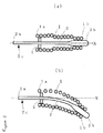
- FIGs. 6A and 6B are vertical sectional views for explaining an operation principle of converting means utilizing induced electromotive force in another embodiment of the present invention, FIG. 6A showing an ordinary state and Figs 6B showing a state that bending force has been applied to a free end. FIGs.
- FIGs. 7A and 7B are vertical sectional views for explaining an operation principle of converting means utilizing magnetic force in another embodiment of the present invention, FIG. 7A showing an ordinary state and FIG. 7B showing a state that bending force has been applied to a free end.
- FIGs. 6A and 6B , and FIGs. 7A and 7B portions substantially equal to those in the embodiment shown in FIG. 1 , FIGs. 2A and 2B , and FIGs. 3A and 3B are attached with same reference numerals and explanation thereof is simplified or omitted.
- a permeability member 24 is attached to the rod member 2 and it configures a portion of the moving end portion 2c.
- the converting means 6 is provided with a coil 64 surrounding the permeability member 24 in an ordinary state and an oscillation circuit 65 connected to the coil 64.
- an ordinary coil iron core member is used in the permeability member 24.
- an ordinary state before application of bending force is put in a state that the permeability member 24 is disposed within the coil 64 (a state shown in FIG. 6A ), and when AC current flows in the coil 64 by the oscillation circuit 65, strong induced electromotive force is generated.
- the rod member 2 is flexed, the moving end portion 2 moves toward the free end 2b, and a state that the permeability member 24 is out of the coil 64 (a state shown in FIG. 6B ) takes place so that weak electromotive force is only generated even if AC current flows in the coil 64 by the oscillation circuit 65. Therefore, by performing conversion to electrical signal binary utilizing strong and weak of the induced electromotive force and causing two values of the binary to correspond to two predetermined actions respectively, switching operation between these two actions can be performed.
- a magnetic body 25 is attached to the rod member 2 and it configures one portion of the moving end portion 2c.
- the converting means 6 is provided with a magnetic force sensor 66.
- an ordinary permanent magnet is used as the magnetic body 25.
- a known member using a Hall element is used as the magnetic force sensor 66.
- an ordinary state before application of bending force is put in a state that the magnetic body has approached the magnetic force sensor (a state shown in FIG. 7A ), where strong magnetic force is detected by the magnetic force sensor.
- a state that the magnetic body has been separated from the magnetic force sensor (a state shown in FIG. 7B ) takes place, so that weak magnetic force is detected by the magnetic force sensor. Therefore, by performing conversion to electrical signal binary utilizing strong and weak of the magnetic force detected by the magnetic force sensor and causing two values of the binary to correspond to two predetermined actions respectively, switching operation between these two actions can be performed.
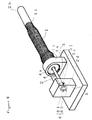
- FIG. 8 is a perspective view showing an appearance of a main constituent portion of an ON/OFF switch according to the embodiment.
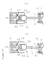
- FIGs . 9A and 9B are vertical sectional views for explaining an operation principle of the ON/OFF switch according to the example, FIG. 9A showing an ordinary state and FIG. 9B showing a state that bending force has been applied to a free end.
- FIGs . 10A and 10B are vertical sectional views for explaining a principle of converting inclination of an end face of the moving end portion to electrical signal binary in the ON/OFF switch according to the example, FIG. 10A showing an ordinary state and FIG.
- FIG. 8 FIGs. 9A and 9B , and FIGs. 10A and 10B , portions substantially equal to those in the embodiments shown in FIG. 1 , FIGs. 2A and 2B , FIGs. 3A and 3B , FIGs. 4A and 4B , FIGs . 5A and 5B , FIGs . 6A and 6B , and FIGs. 7A and 7B are attached with same reference numerals and explanation thereof is simplified or omitted.
- This embodiment has a configuration that the diameter of the insertion hole of the guide 4 in the embodiment shown in FIG. 1 , FIGs . 2A and 2B , and FIGs . 3A and 3B has been enlarged, where limitation to movement of the rod member 2 in a direction perpendicular to the axial line thereof is relaxed. Therefore, as shown in FIGS. 9A and 9B , when bending force is applied to the free end 1b of the cylindrical member 1 so that the cylindrical member 1 is put in a bent state, the moving end portion 2c of the rod member 2 is separated from the original axial line X of the rod member 2 so that the axial line of the bent rod member 2 is put in an inclined state forming an angle to the original axial line X (a state shown in FIG.
- the end face 2d of the moving end portion 2c is also inclined to a state thereof before application of the bending force. Accordingly, regardless of a bending direction of the free end 2b, movement thereof is converted to movement of inclining the end face 2d of the moving end portion 2c of the rod member 2 . Therefore, by converting inclination of the end face 2d of the moving end portion of the rod member 2 to electrical signal binary to output the same and causing two values of the binary to correspond to two predetermined actions respectively, switching operation between these two actions can be performed.
- the surrounding portion 5 is configured so as to surround the moving end portion 2c of the rod member 2 including the end face 2d, and one having the same configuration as that of the embodiment shown in FIGs. 5A and 5B is adopted as the converting means 6.
- an area of the end face 2d of the moving end portion is expanded by the diameter-expanding portion 22 formed on the moving end portion 2c like the embodiment shown in FIGs. 5A and 5B , and a reflecting plate 23 for reflecting light from the light emitting element 61 excellently is attached to the diameter-expanding portion 22, so that a reflecting face of the reflecting plate 23 configures the end face 2d of the moving end portion.
- an ordinary state before application of bending force is put in a state that light from the light emitting element 61 reaches the light receiving element 62 via the end face 2d of the moving end portion (a state shown in FIG. 10A ), and when bending force is applied on the free end 1b of the cylindrical member 1, the rod member 2 is flexed and the end face 2d of the moving end portion is inclined so that a state that an incident angle of light from the light emitting element 61 changes and light from the light emitting element 61 does not reach the light receiving element 62 (a state shown in FIG. 10B ) takes place. Accordingly, by performing conversion to electrical signal binary utilizing presence and absence of light arriving from the light emitting element 61 to the light receiving element 62 and causing two values of the binary to correspond to two predetermined actions respectively, switching operation between these two actions can be performed.
Landscapes
- Push-Button Switches (AREA)
- Switches Operated By Changes In Physical Conditions (AREA)
Claims (6)
- Interrupteur Marche/Arrêt, dans lequel une extrémité (1a) d'un élément cylindrique (1) étant flexible et étirable de manière à pouvoir revenir librement à un état normal est fixée à un élément de base (3), un élément de tige (2) flexible est inséré dans l'élément cylindrique, une extrémité (2b) de l'élément de tige est fixée à une portion d'extrémité (1b) de l'élément cylindrique qui n'est pas fixée à l'élément de base tandis que l'autre extrémité (2a) de celui-ci fait saillie de l'élément cylindrique, une portion adjacente (5) entourant la portion d'extrémité de l'élément de tige qui fait saillie sans contact de l'élément cylindrique est prévue, et dans la portion adjacente est prévue une unité de conversion (6) convertissant le mouvement de la portion d'extrémité de l'élément de tige faisant saillie de l'élément cylindrique par rapport à la portion adjacente en signaux électriques binaires pour fournir en sortie deux valeurs du binaire,
caractérisé en ce que
l'élément de tige est supporté par un guide (4) maintenant un état d'une ligne axiale de l'élément de tige par rapport à l'élément cylindrique, quel que soit l'état de l'élément cylindrique. - Interrupteur Marche/Arrêt selon la revendication 1, dans lequel l'unité de conversion est munie d'un élément émetteur de lumière et d'un élément récepteur de lumière pour réaliser la conversion en signaux électriques binaires en se basant sur la présence et l'absence de lumière arrivant de l'élément émetteur de lumière à l'élément récepteur de lumière.
- Interrupteur Marche/Arrêt selon la revendication 2, dans lequel l'élément émetteur de lumière et l'élément récepteur de lumière sont agencés dans une relation de position où un trajet lumineux arrivant de l'élément émetteur de lumière à l'élément récepteur de lumière croise un parcours en mouvement de la portion d'extrémité de l'élément de tige faisant saillie de l'élément cylindrique.
- Interrupteur Marche/Arrêt selon la revendication 2, dans lequel l'élément émetteur de lumière et l'élément récepteur de lumière sont agencés dans une relation de position où la lumière provenant de l'élément émetteur de lumière est reflétée par une face d'extrémité de la portion d'extrémité de l'élément de tige faisant saillie de l'élément cylindrique à une position prédéterminée pour atteindre l'élément récepteur de lumière.
- Interrupteur Marche/Arrêt selon l'une quelconque des revendications précédentes, dans lequel la portion d'extrémité de l'élément de tige faisant saillie de l'élément cylindrique comprend un élément de perméabilité fixé à l'élément de tige, et l'unité de conversion est munie d'une bobine entourant l'élément de perméabilité dans un état ordinaire et d'un circuit d'oscillation connecté à la bobine pour réaliser la conversion en signaux électriques binaires en se basant sur le niveau élevé et faible de la force électromotrice induite.
- Interrupteur Marche/Arrêt selon l'une quelconque des revendications précédentes, dans lequel la portion d'extrémité de l'élément de tige faisant saillie de l'élément cylindrique comprend un corps magnétique fixé à l'élément de tige, et l'unité de conversion est munie d'un capteur de force magnétique pour réaliser la conversion en signaux électriques binaires en se basant sur le niveau élevé et faible de la force magnétique détectée par le capteur de force magnétique.
Priority Applications (1)
| Application Number | Priority Date | Filing Date | Title |
|---|---|---|---|
| EP20090150121 EP2204829B1 (fr) | 2009-01-06 | 2009-01-06 | Commutation marche/arrêt |
Applications Claiming Priority (1)
| Application Number | Priority Date | Filing Date | Title |
|---|---|---|---|
| EP20090150121 EP2204829B1 (fr) | 2009-01-06 | 2009-01-06 | Commutation marche/arrêt |
Publications (2)
| Publication Number | Publication Date |
|---|---|
| EP2204829A1 EP2204829A1 (fr) | 2010-07-07 |
| EP2204829B1 true EP2204829B1 (fr) | 2011-10-05 |
Family
ID=40717014
Family Applications (1)
| Application Number | Title | Priority Date | Filing Date |
|---|---|---|---|
| EP20090150121 Active EP2204829B1 (fr) | 2009-01-06 | 2009-01-06 | Commutation marche/arrêt |
Country Status (1)
| Country | Link |
|---|---|
| EP (1) | EP2204829B1 (fr) |
Family Cites Families (6)
| Publication number | Priority date | Publication date | Assignee | Title |
|---|---|---|---|---|
| US1782516A (en) * | 1930-04-08 | 1930-11-25 | Nat Mfg Co | Electric switch |
| US4459022A (en) * | 1980-10-16 | 1984-07-10 | United Technologies Corporation | Fiber optic angular sensor |
| FR2575845B1 (fr) | 1985-01-07 | 1987-03-27 | Saf Chainette | Manipulateur de commande resistant aux chocs |
| US4994669A (en) * | 1990-07-29 | 1991-02-19 | Stern Michael A | Opto-electrical joystick switch having a resilient, rigidly mounted central shaft |
| DE69720854T2 (de) * | 1996-05-29 | 2003-11-20 | Fujitsu Takamisawa Component Ltd., Tokio/Tokyo | Führungsvorrichtung zum Verschieben und Positionieren eines Zeigers auf einem Computerbildschirm |
| JP2009026509A (ja) * | 2007-07-18 | 2009-02-05 | Anywire:Kk | オンオフスイッチ |
-
2009
- 2009-01-06 EP EP20090150121 patent/EP2204829B1/fr active Active
Also Published As
| Publication number | Publication date |
|---|---|
| EP2204829A1 (fr) | 2010-07-07 |
Similar Documents
| Publication | Publication Date | Title |
|---|---|---|
| US20100171026A1 (en) | On/off switch | |
| US8284003B2 (en) | Operating element having improved tilting haptics | |
| US8760246B2 (en) | Reed switch | |
| US8581682B2 (en) | Magnet aided solenoid for an electrical switch | |
| US7348506B2 (en) | Linear pressure sensor | |
| JP2009026509A (ja) | オンオフスイッチ | |
| KR20230066657A (ko) | 스위칭 장치 | |
| KR102330627B1 (ko) | 중간 전압 접촉기 | |
| US12119193B2 (en) | Electromagnetic energy converter | |
| EP2204829B1 (fr) | Commutation marche/arrêt | |
| US20190219165A1 (en) | Electronic shift control device | |
| JP2021026881A (ja) | 押しボタンスイッチ | |
| CN105393328B (zh) | 电开关触头和具有相同电开关触头的开关设备 | |
| US11158476B2 (en) | Electromagnetic relay | |
| CN106796858B (zh) | 接点开闭装置 | |
| JP2009026509A5 (fr) | ||
| US10607799B2 (en) | Electrical switch having a direct armature coupling | |
| JP3170219U (ja) | オンオフスイッチ | |
| KR200489974Y1 (ko) | 전자접촉기 액추에이터 | |
| EP4120309A1 (fr) | Composant de commutation comprenant des ensembles support mobile intégrés | |
| US11887797B2 (en) | Electrical switching element comprising a direct armature coupling | |
| JP2008277051A (ja) | 磁気近接スイッチ | |
| JP3148937U (ja) | 非接触型オンオフスイッチのスイッチレバー | |
| KR102349635B1 (ko) | 전기 플러그 커넥터 장치 | |
| JP6575343B2 (ja) | リレー |
Legal Events
| Date | Code | Title | Description |
|---|---|---|---|
| PUAI | Public reference made under article 153(3) epc to a published international application that has entered the european phase |
Free format text: ORIGINAL CODE: 0009012 |
|
| AK | Designated contracting states |
Kind code of ref document: A1 Designated state(s): AT BE BG CH CY CZ DE DK EE ES FI FR GB GR HR HU IE IS IT LI LT LU LV MC MK MT NL NO PL PT RO SE SI SK TR |
|
| AX | Request for extension of the european patent |
Extension state: AL BA RS |
|
| 17P | Request for examination filed |
Effective date: 20100924 |
|
| 17Q | First examination report despatched |
Effective date: 20101109 |
|
| AKX | Designation fees paid |
Designated state(s): DE |
|
| GRAP | Despatch of communication of intention to grant a patent |
Free format text: ORIGINAL CODE: EPIDOSNIGR1 |
|
| RIN1 | Information on inventor provided before grant (corrected) |
Inventor name: KENJI NISHIKIDO Inventor name: YOSHITANE SAITOU |
|
| GRAS | Grant fee paid |
Free format text: ORIGINAL CODE: EPIDOSNIGR3 |
|
| GRAA | (expected) grant |
Free format text: ORIGINAL CODE: 0009210 |
|
| AK | Designated contracting states |
Kind code of ref document: B1 Designated state(s): DE |
|
| REG | Reference to a national code |
Ref country code: DE Ref legal event code: R096 Ref document number: 602009002900 Country of ref document: DE Effective date: 20111201 |
|
| PLBE | No opposition filed within time limit |
Free format text: ORIGINAL CODE: 0009261 |
|
| STAA | Information on the status of an ep patent application or granted ep patent |
Free format text: STATUS: NO OPPOSITION FILED WITHIN TIME LIMIT |
|
| 26N | No opposition filed |
Effective date: 20120706 |
|
| REG | Reference to a national code |
Ref country code: DE Ref legal event code: R097 Ref document number: 602009002900 Country of ref document: DE Effective date: 20120706 |
|
| PGFP | Annual fee paid to national office [announced via postgrant information from national office to epo] |
Ref country code: DE Payment date: 20260121 Year of fee payment: 18 |