EP2204971B1 - Dispositif à affichage roulant doté d'une diminution de la contrainte - Google Patents
Dispositif à affichage roulant doté d'une diminution de la contrainte Download PDFInfo
- Publication number
- EP2204971B1 EP2204971B1 EP10159558.5A EP10159558A EP2204971B1 EP 2204971 B1 EP2204971 B1 EP 2204971B1 EP 10159558 A EP10159558 A EP 10159558A EP 2204971 B1 EP2204971 B1 EP 2204971B1
- Authority
- EP
- European Patent Office
- Prior art keywords
- rollable display
- bolt
- slot
- cavity
- housing
- Prior art date
- Legal status (The legal status is an assumption and is not a legal conclusion. Google has not performed a legal analysis and makes no representation as to the accuracy of the status listed.)
- Expired - Lifetime
Links
Images



Classifications
-
- G—PHYSICS
- G09—EDUCATION; CRYPTOGRAPHY; DISPLAY; ADVERTISING; SEALS
- G09F—DISPLAYING; ADVERTISING; SIGNS; LABELS OR NAME-PLATES; SEALS
- G09F9/00—Indicating arrangements for variable information in which the information is built-up on a support by selection or combination of individual elements
- G09F9/30—Indicating arrangements for variable information in which the information is built-up on a support by selection or combination of individual elements in which the desired character or characters are formed by combining individual elements
- G09F9/301—Indicating arrangements for variable information in which the information is built-up on a support by selection or combination of individual elements in which the desired character or characters are formed by combining individual elements flexible foldable or roll-able electronic displays, e.g. thin LCD, OLED
-
- H—ELECTRICITY
- H04—ELECTRIC COMMUNICATION TECHNIQUE
- H04M—TELEPHONIC COMMUNICATION
- H04M1/00—Substation equipment, e.g. for use by subscribers
- H04M1/02—Constructional features of telephone sets
- H04M1/0202—Portable telephone sets, e.g. cordless phones, mobile phones or bar type handsets
- H04M1/026—Details of the structure or mounting of specific components
- H04M1/0266—Details of the structure or mounting of specific components for a display module assembly
- H04M1/0268—Details of the structure or mounting of specific components for a display module assembly including a flexible display panel
-
- G—PHYSICS
- G06—COMPUTING OR CALCULATING; COUNTING
- G06F—ELECTRIC DIGITAL DATA PROCESSING
- G06F1/00—Details not covered by groups G06F3/00 - G06F13/00 and G06F21/00
- G06F1/16—Constructional details or arrangements
- G06F1/1613—Constructional details or arrangements for portable computers
- G06F1/1633—Constructional details or arrangements of portable computers not specific to the type of enclosures covered by groups G06F1/1615 - G06F1/1626
- G06F1/1637—Details related to the display arrangement, including those related to the mounting of the display in the housing
- G06F1/1652—Details related to the display arrangement, including those related to the mounting of the display in the housing the display being flexible, e.g. mimicking a sheet of paper, or rollable
-
- G—PHYSICS
- G02—OPTICS
- G02F—OPTICAL DEVICES OR ARRANGEMENTS FOR THE CONTROL OF LIGHT BY MODIFICATION OF THE OPTICAL PROPERTIES OF THE MEDIA OF THE ELEMENTS INVOLVED THEREIN; NON-LINEAR OPTICS; FREQUENCY-CHANGING OF LIGHT; OPTICAL LOGIC ELEMENTS; OPTICAL ANALOGUE/DIGITAL CONVERTERS
- G02F1/00—Devices or arrangements for the control of the intensity, colour, phase, polarisation or direction of light arriving from an independent light source, e.g. switching, gating or modulating; Non-linear optics
- G02F1/01—Devices or arrangements for the control of the intensity, colour, phase, polarisation or direction of light arriving from an independent light source, e.g. switching, gating or modulating; Non-linear optics for the control of the intensity, phase, polarisation or colour
- G02F1/13—Devices or arrangements for the control of the intensity, colour, phase, polarisation or direction of light arriving from an independent light source, e.g. switching, gating or modulating; Non-linear optics for the control of the intensity, phase, polarisation or colour based on liquid crystals, e.g. single liquid crystal display cells
- G02F1/133—Constructional arrangements; Operation of liquid crystal cells; Circuit arrangements
- G02F1/1333—Constructional arrangements; Manufacturing methods
- G02F1/133305—Flexible substrates, e.g. plastics, organic film
-
- H—ELECTRICITY
- H04—ELECTRIC COMMUNICATION TECHNIQUE
- H04M—TELEPHONIC COMMUNICATION
- H04M2250/00—Details of telephonic subscriber devices
- H04M2250/16—Details of telephonic subscriber devices including more than one display unit
Definitions
- This invention relates generally to a rollable display device comprising an inner housing, the inner housing having a slot; a rollable display, the rollable display having a bend portion, the bend portion being disposed through the inner slot.
- the rollable display device 10 includes an inner housing 12, such as an inner cylinder, housing the electronics 14, and an outer housing 16, such as an outer cylinder, disposed about the inner housing 12.
- the wall of the inner housing 12 forms an inner slot 13 and the wall of the outer housing 16 forms an outer slot 17.
- a rollable display 18 includes a connection portion 20, a bend portion 22, a rolled portion 24, and an external portion 26.
- the rollable display 18 is connected to the electronics 14 by the connection portion 20, passes through the inner slot 13 at the bend portion 22, wraps around the inner housing 12, and exits the outer housing 16 at the external portion 26.
- the rollable display 18 is deployed for use by extending the rolled portion 24 through the outer slot 17.
- the rolled portion 24 is extended and retracted manually or by motor power.
- the rolled portion 24 typically makes a gradual, large-radius curve around the inner housing 12, so the stress and resulting strain is limited below a design threshold, preventing damage.
- a radius greater than 7 millimeters for a 100 ⁇ meter thick rollable display typically holds strains in the electrically active region of the rollable display below a 1 percent limit.
- the sharp bending of the display 18 at the bend portion 22 exceeds the design threshold and damages the rollable display 18 over time from repetitive strain. Examples of display failures include broken circuits, layer delamination, cracking, and buckling.
- Such failures may prevent the rollable display from rolling and unrolling, may reduce the image quality of the rollable display, or may prevent the rollable display from functioning. Excessive strain in the bend portion 22 may also interfere with the connection of the rollable display 18 to the electronics 14 at the connection portion 20.
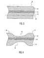
- FIG. 3 is a cross section view of a portion of a rollable display.
- the rollable display 30 includes a first layer 32, a second layer 34, and a third layer 36.
- the layers are laminated together to form the rollable display 30.
- the first layer. 32 is typically a substrate for supporting the much thinner second layer 34, which is typically a fragile electronics layer.
- the third layer 36 is typically an electronic ink layer responsive to electrical charge from the second layer 34 to display text or graphical information to the user.
- the rollable display 30 has a neutral line 38, which is free of stress when the reliable display 30 is bent, such as when bending the rolled portion around the inner housing or the bend portion through the inner slot.
- the location of the neutral line 38 depends on the thickness and modulus of elasticity of each layer making up the rollable display 30.
- the rollable display 30 When bent, the rollable display 30 is in tension on one side of the neutral line 38 and in compression on the other side. Repeated cycling of the rollable display 30 to a radius smaller than the minimum design radius can result in failure of the rollable display 30.
- FIGS. 4 - 6 showing embodiments not covered by the invention and in which like elements share like reference numbers, are cross section views of a bend portion of a rollable display with strain reduction.
- FIG. 4 provides an example of strain reduction by increasing radius of the bend portion.
- FIGS. 5 & 6 provide examples of strain reduction by location the neutral line at a selected layer of the bend portion.
- the channels 42 act as strain reducers by thinning the rollable display at the bend portion 31, which increases the radius of the bend at the inner slot in the inner housing. A larger bend radius reduces strain from repetitive cycling and protects the selected fragile layer from damage.
- only a single channel 42 is formed in the first layer 32 or the third layer 36, rather than both layers, as the strain reducer 40.
- the thickness of the channel 42 is selected to locate the neutral line of the bend portion 31 at a selected layer.
- FIGS. 5 & 6 provide examples of strain reduction by location the neutral line at a selected layer of the bend portion.
- FIG. 5 uses an alternative material portion in one of the layers as the strain reducer and
- FIG. 6 uses an additional layer as the strain reducer.
- the strain reducer 40 includes an alternative material portion 54 disposed in the third layer 36 of the bend portion 31 parallel to the central axis of the rollable display when rolled.
- the material of the alternative material portion 54 is a different material than the original third layer material 52 and is selected for its modulus of elasticity so that the neutral line 38 is at the selected layer.
- the alternative material portion 54 can be of any desired thickness to move the neutral line 38 to the desired layer, i.e., thinner, thicker, or the same thickness as the third layer material 52.
- the neutral line 38 is located in the second layer 34 under the alternative material portion 54 and in the first layer 32 under the original third layer material 52.
- the second layer 34 is typically the fragile electronics layer.
- Locating the neutral line at the selected layer as used herein includes locating the neutral line near the selected layer.
- the neutral line need not be precisely on the selected layer to effect the desired strain reduction. Strain is proportional to the distance between the selected layer and the neutral line, so any reduction in the distance provides stress reduction. In one example, effective stress reduction is provided by locating the neutral line within 20 ⁇ meters of a 2 ⁇ meters thick electronics layer in a 100 ⁇ meters thick display.
- the alternative material portion 54 can be made of any polymer, plastic, or other material compatible with the surrounding materials and providing the desired modulus of elasticity. Exemplary materials include polyamide, polyethylene terephthalate (PET), and the like. In one embodiment, the alternative material portion 54 is formed of a uniform material.
- the alternative material portion 54 is formed of layers of material. In another alternative embodiment, the alternative material portion 54 is formed of two or more interspersed materials, such as spheres or voids dispersed in another material. Those skilled in the art will appreciate that additional alternative material portions can be included in other layers on both or either side of the neutral line to precisely locate the neutral line.
- the strain reducer 40 includes a fourth layer 62 disposed on the third layer 36 of the bend portion 31 to locate the neutral line 38 at a selected layer of the bend portion 31.
- the thickness and modulus of elasticity of the fourth layer 62 are selected to locate the neutral line 38 as desired. Locating the neutral line at the selected layer as used herein includes locating the neutral line near the selected layer.
- the fourth layer 62 can be formed of a single or multiple materials, in a uniform layer or in a more complex configuration, such as spheres or layers.
- the fourth layer 62 can be made of any polymer, plastic, or other material compatible with the surrounding materials and providing the desired modulus of elasticity. Exemplary materials include polyamide, polyethylene terephthalate (PET), and the like.
- PET polyethylene terephthalate
- FIGS. 7 & 8 are perspective views of an embodiment of a rollable display device with strain reduction made in accordance with the present invention.
- FIGS. 7 & 8 show the strain reducer disengaged and engaged, respectively.
- the strain reducer maintains a desired length of the rollable display within the outer housing, reducing cycling and repetitive stress at the bend portion.
- An outer housing 104 is rotatably disposed about an inner housing 102.
- the inner housing 102 includes an inner slot 108 and the outer housing 104 includes an outer slot 114.
- the rollable display 106 is connected to the inner housing 102 and has a bend portion 118, which is located at the inner slot 108 of the inner housing 102 where the rollable display 106 passes through the inner housing 102.
- the rollable display 106 passes through the outer slot 114 of the outer housing 104. In operation, the rollable display 106 rolls around the inner housing 102 when the rollable display 106 is retracted into the outer housing 104.
- the strain reducer 100 includes a bolt 110 slidably disposed in an opening 112 in the inner housing 102 and a cavity 116 formed in the outer housing 104.
- a spring (not shown), such as a leaf spring or a coil spring, urges the bolt 110 toward the outer housing 104.
- the cavity 116 is located a first distance 101 from the outer slot 114 and the opening 112 is located a second distance 103 from the inner slot 108.
- the cavity 116 passes through the wall of the outer housing 104.
- the cavity 116 passes part way into the wall of the outer housing 104.
- the bolt 110 is depressed into the opening 112 by the rollable display 106 when the strain reducer 100 is disengaged.
- the rollable display 106 separates the bolt 110 from the outer housing 104.
- the rollable display 106 moves through the outer slot 114 as the rollable display 106 is deployed through the outer slot 114.
- the bolt 110 is aligned with the cavity 116, the bolt 110 is received in the cavity 116 so that the strain reducer 100 is engaged.
- the engaged strain reducer 100 prevents further motion of the inner housing 102 relative to the outer housing 104. This assures that a desired length of the rollable display 106 remains within the outer housing 104, avoiding cycling and repetitive strain on the bend portion 118.
- the desired length is set by the difference between the first distance 101 and the second distance 103.
- the desired length is independent of the total length of the rollable display 106, allowing the rollable display device to be used with different length rollable displays.
- FIG. 9 is cross section view of an alternative embodiment for an extended cavity of a rollable display device with strain reduction made in accordance with the present invention.
- the extended cavity 122 is formed in the outer housing 104.
- the extended cavity 122 includes a first cavity 116 at a first distance 101 from the outer slot 114, a second cavity 132 at a third distance 121 from the outer slot 114, and a transition cavity 130 connecting the first cavity 116 and the second cavity 132.
- the transition cavity 130 includes a bump 128 near the first cavity 116.
- a spring 134 urges bolt 110, which is coupled to the inner housing (not shown), toward the outer housing 104.
- the bolt 110 is depressed toward the inner housing by the rollable display (not shown), until the bolt 110 is aligned with the first cavity 116 through the relative rotation of the inner housing and the outer housing 104.
- the bolt 110 is received in the first cavity 116 and further relative rotation impeded by the bump 128.
- a desired length of the rollable display remains between the outer slot 114 and the inner slot (not shown) to reduce cycling of the bend portion and provide strain reduction.
- the third distance 121 is equal to the distance between the bolt 110 and the inner slot (the second distance 103 of FIG. 8 ), so that the inner slot and outer slot 114 are aligned when the bolt 110 is received in the second cavity 132. Alignment of the inner slot and outer slot 114 permits removal and replacement of the rollable display.
- Certain configurations of the rollable display device provide electronics within the inner housing and a connection portion of the rollable display connectable to the electronics. The connection portion is detachable from the electronics when the inner slot is aligned with the outer slot 114.
- the bolt 110 is coupled to a switch 124 responsive to the position of the bolt 110.
- the switch 124 has two or more states depending on the position of the bolt 110. In one embodiment, the switch 124 has one state when the bolt is separated from the outer housing 104 by the rollable display and another state when the bolt 110 is received in the first cavity 116. In another embodiment, the switch 124 has yet another state when the bolt 110 is received in the second cavity 132, such as when the inner slot and outer slot 114 are aligned.
- FIG. 10 is a top view of an alternative embodiment for an outer housing of a rollable display device with strain reduction made in accordance with the present invention.
- the bolt is not received in a cavity, but tracks in a spiral groove 140 formed on the inside wall of the outer housing 104 free of the outer slot 114.
- the spiral groove 140 is stopped at a first end 142 and a second end 144.
- the inner housing makes a predetermined number of rotations relative to the outer housing 104, allowing a predetermined length of the rollable display to be deployed.
- the first end 142 of the spiral groove 140 can be positioned to assure that a desired length of the rollable display remains within the outer housing 104.
- the location of the spiral groove 140 and the bolt can be reversed, with the spiral groove formed on the outside wall of the inner housing and the bolt operably attached to the outer housing.
- the bolt is of a fixed length, rather than being spring loaded.
- FIG. 11 is a perspective view of another alternative embodiment of a rollable display device with strain reduction made in accordance with the present invention.
- the strain reducer maintains a desired length of the rollable display within the outer housing, reducing cycling and repetitive stress at the bend portion. Aligning the outer slot 114 and the inner slot 108 allows a latch 205 to release the rollable display 106 from a display connection 212.
- the strain reducer 100 includes a bolt 110 slidably and movably disposed in an opening 112 in the inner housing 102 and a cavity 116 formed in the outer housing 104.
- a spring 201 such as a leaf spring or a coil spring, urges the bolt 110 toward the outer housing 104.
- the cavity 116 passes through the wall of the outer housing 104.
- the cavity 116 passes part way into the wall of the outer housing 104.
- the bolt 110 and spring 201 are operably connected to mounting 202, which pivots about pin 210, moving the bolt 110 along the length of the opening 112.
- the pin 210 and spring 201 are supported by an endcap (not shown) of the inner housing 102.
- the bolt 110 is moveable from one distance to the inner slot 108 when the bolt 110 is at the end:of the opening 112 away from the inner slot 108 to another distance to the inner slot 108 when the bolt 110 is at the end of the opening 112 near the inner slot 108.
- Spring 203 urges the mounting 202 and bolt 110 toward the end of the opening 112 away from the inner slot 108.
- a foot 206 is operably connected to the mounting 202 and is aligned to engage a latch 205 of a display connection 212 to disconnect the rollable display 106.
- the dashed line between the foot 206 and latch 205 indicates the path of the foot 206.
- the connection portion 216 of the rollable display 106 is connected to electronics (not shown) by the display connection 212.
- the bolt 110 is depressed into the opening 112 by the rollable display 106 when the strain reducer 100 is disengaged.
- the rollable display 106 separates the bolt 110 from the outer housing 104.
- the Tollable display 106 moves through the outer slot 114 as the rollable display 106 is deployed through the outer slot 114.
- the bolt 110 is aligned with the cavity 116, the bolt 110 is received in the cavity 116 so that the strain reducer 100 is engaged.
- the engaged strain reducer 100 resists further motion of the inner housing 102 relative to the outer housing 104 due to the resistance of the spring 203. This assures that a desired length of the rollable display 106 remains within the outer housing 104, avoiding cycling and repetitive strain on the bend portion 118.
- the bolt 110 can be moved to the end of the opening 112 nearer the inner slot 108. In this position, the outer slot 114 and the inner slot 108 are aligned allowing removal and replacement of the rollable display 106.
- the foot 206 engages the latch 206, moving the clamp mechanism 204 away from the connection block 214, and releasing the connection portion 216 of the rollable display 106.
- the rollable display 106 can be replaced with a new rollable display 106 in the display connection 212.
- the bolt 110 is rotated toward the end of the opening 112 away from the inner slot 108, disengaging the foot 206 from the latch 206, so that the display connection 212 connects to the connection portion 216 of the rollable display 106.
- the embodiments of the invention disclosed herein are presently considered to be preferred, various changes and modifications can be made without departing from the scope of the invention.
- Those skilled in the art will appreciate that various designs are possible for the strain reducer 100.
- the strain reduction approaches discussed separately above can be combined to produce additional protection of the Tollable display from repetitive strain.
- the bolt 110 is attached to the outer housing 104 and urged toward the inner housing 102, which includes a cavity.
- the scope of the invention is indicated in the appended claims, and all changes that come within the meaning and range of equivalents are intended to be embraced therein.
Landscapes
- Engineering & Computer Science (AREA)
- Physics & Mathematics (AREA)
- Theoretical Computer Science (AREA)
- General Physics & Mathematics (AREA)
- Signal Processing (AREA)
- Computer Hardware Design (AREA)
- Nonlinear Science (AREA)
- Mathematical Physics (AREA)
- General Engineering & Computer Science (AREA)
- Chemical & Material Sciences (AREA)
- Crystallography & Structural Chemistry (AREA)
- Human Computer Interaction (AREA)
- Optics & Photonics (AREA)
- Devices For Indicating Variable Information By Combining Individual Elements (AREA)
- Fittings On The Vehicle Exterior For Carrying Loads, And Devices For Holding Or Mounting Articles (AREA)
- Lighting Device Outwards From Vehicle And Optical Signal (AREA)
- Casings For Electric Apparatus (AREA)
Claims (11)
- Dispositif à affichage roulant comportant:une enveloppe interne (102), cette enveloppe interne (102) comprenant une rainure interne (108);un affichage roulant (106), cet affichage roulant (106) ayant une partie recourbée (118) et la partie recourbée (118) étant disposée à travers la rainure interne (108),caractérisé en ce quele dispositif à affichage roulant comprend un réducteur de contrainte (100) raccordé à l'affichage roulant (106) et servant à réduire la contrainte exercée au niveau de la partie recourbée (118),le dispositif comprenant par ailleurs une enveloppe externe (104) capable de tourner autour de l'enveloppe interne (102), l'enveloppe externe (104) ayant une rainure externe (114), et l'affichage roulant (106) étant disposé à travers la rainure externe (114);caractérisé en ce que le réducteur de contrainte (100) comprend une première cavité (116) formée dans l'enveloppe externe (104) à une première distance mesurée à partir de la rainure externe (114), un boulon (110) situé à une deuxième distance (103) mesurée à partir de la rainure interne (108) et qui est poussé vers l'enveloppe externe (104);caractérisé en ce que le boulon (110) est reçu dans la première cavité (116) lorsque le boulon (110) se trouve aligné sur la première cavité (116), et la différence entre la première distance (101) et la deuxième distance (103) sert de longueur recherchée pour l'affichage roulant (106) entre la rainure interne (108) et la rainure externe (114) lorsque le boulon (110) se trouve aligné sur la première cavité (116).
- Dispositif selon la revendication 1, comportant par ailleurs un commutateur (124) qui réagit à la position du boulon (110).
- Dispositif selon la revendication 2, caractérisé en ce que le commutateur (124) sert à brancher une fonction du dispositif qui est sélectionnée dans le groupe comprenant l'énergie électrique qui alimente le moteur d'entraînement, l'énergie électrique qui alimente les circuits électroniques, le mode de fonctionnement des circuits électroniques, l'énergie électrique pour la présentation des images sur l'affichage roulant, et le raccordement à l'affichage roulant.
- Dispositif selon la revendication 1, caractérisé en ce que l'affichage roulant (106) pousse le boulon (110) vers l'enveloppe interne (102) lorsque le boulon (110) ne se trouve pas aligné sur la première cavité (116).
- Dispositif selon la revendication 1, comportant par ailleurs une deuxième cavité (132) formée dans l'enveloppe externe (104) à une troisième distance mesurée à partir de la rainure externe (114), et une cavité de transition (130) formée dans l'enveloppe externe (104) entre la première cavité (116) et la deuxième cavité (132).
- Dispositif selon la revendication 5, caractérisé en ce que la deuxième distance et la troisième distance sont égales.
- Dispositif selon la revendication 1, caractérisé en ce que l'enveloppe interne (102) comporte par ailleurs des circuits électroniques (14) et en ce que l'affichage roulant (106) comporte par ailleurs un raccordement (20) qui peut être connecté aux circuits électroniques (14), caractérisé en ce que le raccordement (20) peut être déconnecté des circuits électroniques (14) lorsque la rainure interne (108) se trouve alignée sur la rainure externe (114).
- Dispositif selon la revendication 5, comportant par ailleurs un commutateur qui réagit au mouvement du boulon (110), le commutateur se trouvant dans un premier état lorsque le boulon (110) est reçu dans la première cavité (116), et dans un deuxième état lorsque le boulon (110) est reçu dans la deuxième cavité (132).
- Dispositif selon la revendication 1, caractérisé en ce que le boulon (110) peut être déplacé jusqu'au tiers de la distance à partir de la rainure interne (108), cette rainure interne (108) étant alignée sur la rainure externe (114) lorsque le boulon (110) se trouve au tiers de la distance.
- Dispositif selon la revendication 1, comportant par ailleurs un patin (206) raccordé de manière utilisable au boulon (110), un raccord d'affichage (212) adapté de manière à recevoir un raccordement (216) de l'affichage roulant (106) et ayant un verrou (205), caractérisé en ce que le patin (206) est utilisé pour entrer en contact avec le verrou (205) et déconnecter le raccordement (216) du raccord d'affichage (212) lorsque la rainure interne (108) est alignée sur la rainure externe (114).
- Dispositif à affichage roulant comportant:une enveloppe interne (102), cette enveloppe interne (102), comprenant une rainure interne (108);un affichage roulant (106), cet affichage roulant (106) ayant une partie recourbée (118), et la partie recourbée (118) étant disposée à travers la rainure interne (108),caractérisé en ce quele dispositif à affichage roulant comprend un réducteur de contrainte (100) raccordé à l'affichage roulant (106) et servant à réduire la contrainte exercée au niveau de la partie recourbée (118),le dispositif comprenant par ailleurs une enveloppe externe (104) capable de tourner autour de l'enveloppe interne (102);caractérisé en ce que le réducteur de contrainte (100) comporte une rainure en spirale (140) formée soit dans l'enveloppe interne (102) soit dans l'enveloppe externe (104); etun boulon (110) raccordé de manière utilisable à l'enveloppe interne (102) ou bien à l'enveloppe externe (104) qui ne comporte pas la rainure en spirale, le boulon (110) se trouvant à l'intérieur de cette rainure en spirale (140).
Applications Claiming Priority (2)
| Application Number | Priority Date | Filing Date | Title |
|---|---|---|---|
| US57324204P | 2004-05-21 | 2004-05-21 | |
| EP05747167A EP1754100B1 (fr) | 2004-05-21 | 2005-05-16 | Dispositif d'affichage enroulable a force reduite |
Related Parent Applications (2)
| Application Number | Title | Priority Date | Filing Date |
|---|---|---|---|
| EP05747167A Division EP1754100B1 (fr) | 2004-05-21 | 2005-05-16 | Dispositif d'affichage enroulable a force reduite |
| EP05747167.4 Division | 2005-05-16 |
Publications (3)
| Publication Number | Publication Date |
|---|---|
| EP2204971A2 EP2204971A2 (fr) | 2010-07-07 |
| EP2204971A3 EP2204971A3 (fr) | 2014-01-01 |
| EP2204971B1 true EP2204971B1 (fr) | 2014-10-15 |
Family
ID=34970728
Family Applications (2)
| Application Number | Title | Priority Date | Filing Date |
|---|---|---|---|
| EP05747167A Expired - Lifetime EP1754100B1 (fr) | 2004-05-21 | 2005-05-16 | Dispositif d'affichage enroulable a force reduite |
| EP10159558.5A Expired - Lifetime EP2204971B1 (fr) | 2004-05-21 | 2005-05-16 | Dispositif à affichage roulant doté d'une diminution de la contrainte |
Family Applications Before (1)
| Application Number | Title | Priority Date | Filing Date |
|---|---|---|---|
| EP05747167A Expired - Lifetime EP1754100B1 (fr) | 2004-05-21 | 2005-05-16 | Dispositif d'affichage enroulable a force reduite |
Country Status (9)
| Country | Link |
|---|---|
| US (1) | US8001711B2 (fr) |
| EP (2) | EP1754100B1 (fr) |
| JP (1) | JP5090160B2 (fr) |
| KR (1) | KR101186969B1 (fr) |
| CN (2) | CN1973240B (fr) |
| AT (1) | ATE479128T1 (fr) |
| DE (1) | DE602005023152D1 (fr) |
| TW (1) | TWI358623B (fr) |
| WO (1) | WO2005114309A1 (fr) |
Families Citing this family (63)
| Publication number | Priority date | Publication date | Assignee | Title |
|---|---|---|---|---|
| WO2006085271A2 (fr) * | 2005-02-11 | 2006-08-17 | Polymer Vision Limited | Systeme d'affichage enroule comportant un ecran flexible |
| US8477250B2 (en) | 2005-12-16 | 2013-07-02 | Creator Technology B.V. | Circular displays |
| KR101443229B1 (ko) * | 2006-10-19 | 2014-09-22 | 크리에이터 테크놀로지 비.브이. | 두루마리형 또는 감김 가능 디스플레이 장치용 전면 발광 |
| TWI370419B (en) * | 2006-10-31 | 2012-08-11 | Creator Technology Bv | Flexible display supported by hinged frame |
| US8531758B2 (en) | 2007-04-16 | 2013-09-10 | Creator Technology B.V. | Device comprising a multilayer structure and rollers |
| CN101689338B (zh) * | 2007-04-25 | 2013-10-23 | 创造者科技有限公司 | 包括具有压力分散工具的柔性显示器的电子装置 |
| CN103176611A (zh) * | 2011-12-26 | 2013-06-26 | 富泰华工业(深圳)有限公司 | 电子设备及其信息输入装置 |
| CN103376825A (zh) * | 2012-04-16 | 2013-10-30 | 黄泽艺 | 可收缩屏幕技术(电子竹简) |
| KR102079188B1 (ko) | 2012-05-09 | 2020-02-19 | 가부시키가이샤 한도오따이 에네루기 켄큐쇼 | 발광 장치 및 전자 기기 |
| US20130321373A1 (en) * | 2012-05-31 | 2013-12-05 | Semiconductor Energy Laboratory Co., Ltd. | Electronic device, program, and recording medium |
| US8908365B2 (en) | 2012-06-25 | 2014-12-09 | Creator Technology B.V. | Display system having a continuous flexible display with display supports |
| KR102080011B1 (ko) * | 2013-06-13 | 2020-02-24 | 삼성디스플레이 주식회사 | 표시장치 및 그 제조방법 |
| CN103337222B (zh) * | 2013-07-01 | 2015-07-08 | 京东方科技集团股份有限公司 | 柔性显示装置 |
| TWI608328B (zh) * | 2013-10-24 | 2017-12-11 | 緯創資通股份有限公司 | 電子裝置 |
| KR102132235B1 (ko) * | 2013-11-28 | 2020-07-10 | 삼성디스플레이 주식회사 | 플렉서블 표시장치 |
| KR102266941B1 (ko) | 2013-12-19 | 2021-06-18 | 삼성디스플레이 주식회사 | 유기 발광 표시 장치 |
| KR102245808B1 (ko) | 2014-02-12 | 2021-04-30 | 삼성디스플레이 주식회사 | 롤러블 표시 장치 |
| KR20150110848A (ko) * | 2014-03-20 | 2015-10-05 | 삼성디스플레이 주식회사 | 표시 장치 |
| TWI543129B (zh) | 2014-07-22 | 2016-07-21 | Lg顯示器股份有限公司 | 捲軸式顯示裝置 |
| KR102365299B1 (ko) | 2014-08-01 | 2022-02-21 | 삼성디스플레이 주식회사 | 표시 장치 |
| WO2016024742A1 (fr) | 2014-08-09 | 2016-02-18 | LG Display Co.,Ltd. | DISPOSITIF D'AFFICHAGE À DIODES ÉLECTROLUMINESCENTES ORGANIQUES ENROULABLE<u /> |
| KR102218649B1 (ko) | 2014-09-16 | 2021-02-23 | 삼성디스플레이 주식회사 | 롤러블 디스플레이 장치 |
| KR102269135B1 (ko) * | 2014-10-06 | 2021-06-25 | 삼성디스플레이 주식회사 | 표시 장치 |
| KR102319543B1 (ko) * | 2014-10-22 | 2021-11-02 | 삼성디스플레이 주식회사 | 롤러블 표시 장치, 롤러블 표시 장치의 제조 방법 및 플렉서블 표시 장치 |
| KR102300024B1 (ko) | 2014-10-23 | 2021-09-09 | 삼성디스플레이 주식회사 | 표시 장치 |
| KR102326453B1 (ko) * | 2014-11-12 | 2021-11-17 | 삼성디스플레이 주식회사 | 롤러블 표시 장치 |
| KR102326034B1 (ko) * | 2014-11-17 | 2021-11-16 | 삼성디스플레이 주식회사 | 표시 장치 |
| KR102257174B1 (ko) * | 2014-12-03 | 2021-05-28 | 삼성디스플레이 주식회사 | 롤러블 표시 장치 |
| KR102342761B1 (ko) | 2014-12-04 | 2021-12-23 | 삼성디스플레이 주식회사 | 플렉시블 디스플레이 장치 |
| KR102342462B1 (ko) | 2014-12-08 | 2021-12-27 | 삼성디스플레이 주식회사 | 롤러블 표시 장치 |
| US10126778B2 (en) * | 2014-12-25 | 2018-11-13 | Shenzhen Royole Technologies Co., Ltd. | Flexible display device |
| KR101570869B1 (ko) * | 2014-12-31 | 2015-11-23 | 엘지디스플레이 주식회사 | 롤러블 디스플레이 장치 |
| KR102352544B1 (ko) | 2015-01-12 | 2022-01-19 | 삼성디스플레이 주식회사 | 표시 장치 |
| KR102352284B1 (ko) * | 2015-02-02 | 2022-01-18 | 삼성디스플레이 주식회사 | 롤러블 디스플레이 장치 |
| KR102304310B1 (ko) * | 2015-02-13 | 2021-09-23 | 삼성디스플레이 주식회사 | 롤러블 표시 장치 |
| KR102305923B1 (ko) | 2015-02-13 | 2021-09-28 | 삼성디스플레이 주식회사 | 롤러블 표시 장치 |
| KR102342869B1 (ko) | 2015-02-26 | 2021-12-23 | 삼성디스플레이 주식회사 | 가요성 표시 장치 및 이의 제조방법 |
| CN104680943B (zh) * | 2015-03-16 | 2017-07-25 | 京东方科技集团股份有限公司 | 一种显示屏和显示装置 |
| KR102375085B1 (ko) | 2015-04-30 | 2022-03-17 | 삼성디스플레이 주식회사 | 표시 장치 |
| CN104821975B (zh) | 2015-05-25 | 2018-10-30 | 京东方科技集团股份有限公司 | 一种柔性显示装置及其底座 |
| KR102345270B1 (ko) | 2015-06-15 | 2022-01-03 | 삼성디스플레이 주식회사 | 표시장치 |
| KR102025924B1 (ko) | 2015-07-31 | 2019-09-26 | 삼성전자주식회사 | 디스플레이 장치 |
| KR102464260B1 (ko) * | 2015-10-02 | 2022-11-07 | 삼성전자주식회사 | 가변 모바일 기기 |
| EP3173897B1 (fr) | 2015-11-27 | 2019-12-18 | LG Electronics Inc. | Dispositif d'affichage |
| KR102454387B1 (ko) * | 2016-04-29 | 2022-10-14 | 엘지디스플레이 주식회사 | 롤러블 디스플레이 장치 |
| KR102527763B1 (ko) * | 2016-07-06 | 2023-05-02 | 삼성디스플레이 주식회사 | 롤러블 디스플레이 장치 및 롤러블 장치 |
| CN106205390B (zh) | 2016-07-08 | 2018-03-27 | 广东欧珀移动通信有限公司 | 一种电子设备控制方法及电子设备 |
| KR102528529B1 (ko) * | 2016-10-06 | 2023-05-03 | 삼성디스플레이 주식회사 | 롤러블 표시 장치 |
| KR20180046422A (ko) | 2016-10-27 | 2018-05-09 | 삼성디스플레이 주식회사 | 플렉시블 표시 장치 및 그 제조 방법 |
| CN107068895B (zh) * | 2016-12-28 | 2019-09-24 | 上海天马微电子有限公司 | 一种显示面板及其显示器 |
| EP3606621B1 (fr) * | 2017-04-03 | 2022-03-02 | 3M Innovative Properties Company | Appareil anti-chute avec enveloppe de protection et ensemble manchon |
| KR102328176B1 (ko) * | 2017-08-14 | 2021-11-19 | 삼성디스플레이 주식회사 | 표시 장치 및 이의 구동 방법 |
| WO2020065990A1 (fr) * | 2018-09-28 | 2020-04-02 | シャープ株式会社 | Dispositif électronique et conteneur |
| KR102642364B1 (ko) * | 2019-03-27 | 2024-03-04 | 엘지전자 주식회사 | 이동 단말기 |
| KR102752782B1 (ko) * | 2019-07-26 | 2025-01-08 | 엘지디스플레이 주식회사 | 표시 장치 |
| CN110534029B (zh) * | 2019-08-26 | 2021-12-10 | 深圳供电局有限公司 | 一种卷曲式电子铭牌及电子铭牌显示方法 |
| CN111524458B (zh) * | 2020-04-17 | 2022-04-26 | 京东方科技集团股份有限公司 | 一种显示装置 |
| KR20220012682A (ko) * | 2020-07-23 | 2022-02-04 | 엘지디스플레이 주식회사 | 표시 장치 |
| KR20220061418A (ko) * | 2020-11-06 | 2022-05-13 | 삼성전자주식회사 | 플렉서블 디스플레이를 갖는 전자 장치 및 그의 카메라 모듈 제어 방법 |
| KR20230024119A (ko) | 2021-08-11 | 2023-02-20 | 삼성전자주식회사 | 플렉서블 디스플레이를 포함하는 전자 장치 및 그 동작 방법 |
| CN118104221A (zh) | 2021-10-15 | 2024-05-28 | 三星电子株式会社 | 具有柔性显示器的电子装置以及具有柔性显示器的电子装置控制电机驱动的方法 |
| US20230205334A1 (en) * | 2021-12-29 | 2023-06-29 | Tpk Touch Solutions (Xiamen) Inc. | Touch display module |
| KR20250117920A (ko) * | 2024-01-29 | 2025-08-05 | 엘지디스플레이 주식회사 | 폴더블 표시 장치 |
Family Cites Families (9)
| Publication number | Priority date | Publication date | Assignee | Title |
|---|---|---|---|---|
| US2111362A (en) * | 1936-08-26 | 1938-03-15 | Joseph S Fisher | Combined writing instrument and calendar |
| JP4655368B2 (ja) * | 2000-12-12 | 2011-03-23 | 日本電気株式会社 | 移動体端末 |
| JP3864750B2 (ja) * | 2001-10-18 | 2007-01-10 | 株式会社日立製作所 | 表示素子用基板及びそれを用いた表示素子 |
| WO2004001704A1 (fr) | 2002-06-20 | 2003-12-31 | Koninklijke Philips Electronics N.V. | Appareil muni d'un affichage |
| US6762929B2 (en) * | 2002-09-12 | 2004-07-13 | Gateway, Inc. | Display support apparatus |
| US7196692B2 (en) * | 2002-09-30 | 2007-03-27 | Brother Kogyo Kabushiki Kaisha | Input device provided with windable display and foldable keyboard, and personal computer provided with the input device |
| CN100380276C (zh) | 2002-10-04 | 2008-04-09 | 皇家飞利浦电子股份有限公司 | 具有显示器的设备 |
| JP3816457B2 (ja) * | 2003-03-18 | 2006-08-30 | 株式会社東芝 | 表示装置 |
| US7614439B2 (en) * | 2004-10-05 | 2009-11-10 | Stephen Lukos | Roller tube having external slot for mounting sheet material |
-
2005
- 2005-05-16 CN CN2005800161943A patent/CN1973240B/zh not_active Expired - Lifetime
- 2005-05-16 EP EP05747167A patent/EP1754100B1/fr not_active Expired - Lifetime
- 2005-05-16 WO PCT/IB2005/051585 patent/WO2005114309A1/fr not_active Ceased
- 2005-05-16 KR KR1020067024319A patent/KR101186969B1/ko not_active Expired - Fee Related
- 2005-05-16 US US11/569,386 patent/US8001711B2/en not_active Expired - Fee Related
- 2005-05-16 JP JP2007517555A patent/JP5090160B2/ja not_active Expired - Fee Related
- 2005-05-16 EP EP10159558.5A patent/EP2204971B1/fr not_active Expired - Lifetime
- 2005-05-16 AT AT05747167T patent/ATE479128T1/de not_active IP Right Cessation
- 2005-05-16 DE DE602005023152T patent/DE602005023152D1/de not_active Expired - Lifetime
- 2005-05-16 CN CN2010105049567A patent/CN101995727B/zh not_active Expired - Lifetime
- 2005-05-18 TW TW094116104A patent/TWI358623B/zh not_active IP Right Cessation
Also Published As
| Publication number | Publication date |
|---|---|
| KR101186969B1 (ko) | 2012-10-02 |
| WO2005114309A8 (fr) | 2007-01-04 |
| KR20070092597A (ko) | 2007-09-13 |
| CN101995727B (zh) | 2013-07-17 |
| TWI358623B (en) | 2012-02-21 |
| US20070216639A1 (en) | 2007-09-20 |
| JP5090160B2 (ja) | 2012-12-05 |
| CN101995727A (zh) | 2011-03-30 |
| EP2204971A2 (fr) | 2010-07-07 |
| WO2005114309A1 (fr) | 2005-12-01 |
| ATE479128T1 (de) | 2010-09-15 |
| EP2204971A3 (fr) | 2014-01-01 |
| JP2008500593A (ja) | 2008-01-10 |
| CN1973240B (zh) | 2010-12-22 |
| DE602005023152D1 (de) | 2010-10-07 |
| EP1754100B1 (fr) | 2010-08-25 |
| CN1973240A (zh) | 2007-05-30 |
| EP1754100A1 (fr) | 2007-02-21 |
| TW200609712A (en) | 2006-03-16 |
| US8001711B2 (en) | 2011-08-23 |
Similar Documents
| Publication | Publication Date | Title |
|---|---|---|
| EP1754100B1 (fr) | Dispositif d'affichage enroulable a force reduite | |
| CN111664337B (zh) | 柔性显示装置 | |
| CN112991928B (zh) | 电子装置 | |
| WO2023124463A1 (fr) | Dispositif électronique pliable | |
| CN115217838A (zh) | 一种折叠装置及电子设备 | |
| US20220308633A1 (en) | Electronic device | |
| CN112995364B (zh) | 移动终端 | |
| US20220322550A1 (en) | Electronic apparatus | |
| CN113037896A (zh) | 柔性屏组件及电子设备 | |
| EP2403222A1 (fr) | Terminal de communications mobile doté d'un affichage souple | |
| WO2021121157A1 (fr) | Ensemble écran d'affichage souple et dispositif électronique | |
| CN115118802B (zh) | 电子装置 | |
| CN112995365B (zh) | 电子装置 | |
| US8150483B2 (en) | Sliding mechanism and portable electronic device having the same | |
| CN115733909A (zh) | 具有滑动装置壳体和平移柔性显示器的电子装置及对应方法 | |
| JP2012526403A (ja) | ユーザ機器 | |
| CN113936552A (zh) | 柔性屏幕支架及显示装置 | |
| CN115083270B (zh) | 电子装置 | |
| CN113037893A (zh) | 电子设备 | |
| CN113923286A (zh) | 电子设备 | |
| CN114070903A (zh) | 侧滑屏设备 | |
| US20100248795A1 (en) | Information processing terminal | |
| CN113037897A (zh) | 电子设备 | |
| CN116708619B (zh) | 卷轴机构及电子设备 | |
| CN121620925A (zh) | 一种摄像头遮挡装置及电子设备 |
Legal Events
| Date | Code | Title | Description |
|---|---|---|---|
| PUAI | Public reference made under article 153(3) epc to a published international application that has entered the european phase |
Free format text: ORIGINAL CODE: 0009012 |
|
| 17P | Request for examination filed |
Effective date: 20100409 |
|
| AC | Divisional application: reference to earlier application |
Ref document number: 1754100 Country of ref document: EP Kind code of ref document: P |
|
| AK | Designated contracting states |
Kind code of ref document: A2 Designated state(s): AT BE BG CH CY CZ DE DK EE ES FI FR GB GR HU IE IS IT LI LT LU MC NL PL PT RO SE SI SK TR |
|
| AX | Request for extension of the european patent |
Extension state: AL BA HR LV MK YU |
|
| RAP1 | Party data changed (applicant data changed or rights of an application transferred) |
Owner name: CREATOR TECHNOLOGY B.V. |
|
| PUAL | Search report despatched |
Free format text: ORIGINAL CODE: 0009013 |
|
| AK | Designated contracting states |
Kind code of ref document: A3 Designated state(s): AT BE BG CH CY CZ DE DK EE ES FI FR GB GR HU IE IS IT LI LT LU MC NL PL PT RO SE SI SK TR |
|
| AX | Request for extension of the european patent |
Extension state: AL BA HR LV MK YU |
|
| RIC1 | Information provided on ipc code assigned before grant |
Ipc: G02F 1/167 20060101ALN20131122BHEP Ipc: G06F 1/16 20060101ALI20131122BHEP Ipc: G09F 9/30 20060101ALI20131122BHEP Ipc: G02F 1/1333 20060101ALN20131122BHEP Ipc: H04M 1/02 20060101AFI20131122BHEP |
|
| RIC1 | Information provided on ipc code assigned before grant |
Ipc: G09F 9/30 20060101ALI20140514BHEP Ipc: G02F 1/167 20060101ALN20140514BHEP Ipc: H04M 1/02 20060101AFI20140514BHEP Ipc: G02F 1/1333 20060101ALN20140514BHEP Ipc: G06F 1/16 20060101ALI20140514BHEP |
|
| GRAP | Despatch of communication of intention to grant a patent |
Free format text: ORIGINAL CODE: EPIDOSNIGR1 |
|
| INTG | Intention to grant announced |
Effective date: 20140624 |
|
| GRAS | Grant fee paid |
Free format text: ORIGINAL CODE: EPIDOSNIGR3 |
|
| GRAA | (expected) grant |
Free format text: ORIGINAL CODE: 0009210 |
|
| AC | Divisional application: reference to earlier application |
Ref document number: 1754100 Country of ref document: EP Kind code of ref document: P |
|
| AK | Designated contracting states |
Kind code of ref document: B1 Designated state(s): AT BE BG CH CY CZ DE DK EE ES FI FR GB GR HU IE IS IT LI LT LU MC NL PL PT RO SE SI SK TR |
|
| REG | Reference to a national code |
Ref country code: CH Ref legal event code: EP Ref country code: GB Ref legal event code: FG4D |
|
| REG | Reference to a national code |
Ref country code: IE Ref legal event code: FG4D |
|
| REG | Reference to a national code |
Ref country code: AT Ref legal event code: REF Ref document number: 692093 Country of ref document: AT Kind code of ref document: T Effective date: 20141115 |
|
| REG | Reference to a national code |
Ref country code: DE Ref legal event code: R096 Ref document number: 602005044964 Country of ref document: DE Effective date: 20141127 |
|
| REG | Reference to a national code |
Ref country code: NL Ref legal event code: T3 |
|
| REG | Reference to a national code |
Ref country code: AT Ref legal event code: MK05 Ref document number: 692093 Country of ref document: AT Kind code of ref document: T Effective date: 20141015 |
|
| REG | Reference to a national code |
Ref country code: LT Ref legal event code: MG4D |
|
| REG | Reference to a national code |
Ref country code: FR Ref legal event code: PLFP Year of fee payment: 11 |
|
| PG25 | Lapsed in a contracting state [announced via postgrant information from national office to epo] |
Ref country code: LT Free format text: LAPSE BECAUSE OF FAILURE TO SUBMIT A TRANSLATION OF THE DESCRIPTION OR TO PAY THE FEE WITHIN THE PRESCRIBED TIME-LIMIT Effective date: 20141015 Ref country code: IS Free format text: LAPSE BECAUSE OF FAILURE TO SUBMIT A TRANSLATION OF THE DESCRIPTION OR TO PAY THE FEE WITHIN THE PRESCRIBED TIME-LIMIT Effective date: 20150215 Ref country code: FI Free format text: LAPSE BECAUSE OF FAILURE TO SUBMIT A TRANSLATION OF THE DESCRIPTION OR TO PAY THE FEE WITHIN THE PRESCRIBED TIME-LIMIT Effective date: 20141015 Ref country code: ES Free format text: LAPSE BECAUSE OF FAILURE TO SUBMIT A TRANSLATION OF THE DESCRIPTION OR TO PAY THE FEE WITHIN THE PRESCRIBED TIME-LIMIT Effective date: 20141015 Ref country code: PT Free format text: LAPSE BECAUSE OF FAILURE TO SUBMIT A TRANSLATION OF THE DESCRIPTION OR TO PAY THE FEE WITHIN THE PRESCRIBED TIME-LIMIT Effective date: 20150216 |
|
| PG25 | Lapsed in a contracting state [announced via postgrant information from national office to epo] |
Ref country code: PL Free format text: LAPSE BECAUSE OF FAILURE TO SUBMIT A TRANSLATION OF THE DESCRIPTION OR TO PAY THE FEE WITHIN THE PRESCRIBED TIME-LIMIT Effective date: 20141015 Ref country code: CY Free format text: LAPSE BECAUSE OF FAILURE TO SUBMIT A TRANSLATION OF THE DESCRIPTION OR TO PAY THE FEE WITHIN THE PRESCRIBED TIME-LIMIT Effective date: 20141015 Ref country code: AT Free format text: LAPSE BECAUSE OF FAILURE TO SUBMIT A TRANSLATION OF THE DESCRIPTION OR TO PAY THE FEE WITHIN THE PRESCRIBED TIME-LIMIT Effective date: 20141015 Ref country code: SE Free format text: LAPSE BECAUSE OF FAILURE TO SUBMIT A TRANSLATION OF THE DESCRIPTION OR TO PAY THE FEE WITHIN THE PRESCRIBED TIME-LIMIT Effective date: 20141015 |
|
| REG | Reference to a national code |
Ref country code: DE Ref legal event code: R097 Ref document number: 602005044964 Country of ref document: DE |
|
| PG25 | Lapsed in a contracting state [announced via postgrant information from national office to epo] |
Ref country code: SK Free format text: LAPSE BECAUSE OF FAILURE TO SUBMIT A TRANSLATION OF THE DESCRIPTION OR TO PAY THE FEE WITHIN THE PRESCRIBED TIME-LIMIT Effective date: 20141015 Ref country code: DK Free format text: LAPSE BECAUSE OF FAILURE TO SUBMIT A TRANSLATION OF THE DESCRIPTION OR TO PAY THE FEE WITHIN THE PRESCRIBED TIME-LIMIT Effective date: 20141015 Ref country code: CZ Free format text: LAPSE BECAUSE OF FAILURE TO SUBMIT A TRANSLATION OF THE DESCRIPTION OR TO PAY THE FEE WITHIN THE PRESCRIBED TIME-LIMIT Effective date: 20141015 Ref country code: EE Free format text: LAPSE BECAUSE OF FAILURE TO SUBMIT A TRANSLATION OF THE DESCRIPTION OR TO PAY THE FEE WITHIN THE PRESCRIBED TIME-LIMIT Effective date: 20141015 Ref country code: RO Free format text: LAPSE BECAUSE OF FAILURE TO SUBMIT A TRANSLATION OF THE DESCRIPTION OR TO PAY THE FEE WITHIN THE PRESCRIBED TIME-LIMIT Effective date: 20141015 |
|
| PLBE | No opposition filed within time limit |
Free format text: ORIGINAL CODE: 0009261 |
|
| STAA | Information on the status of an ep patent application or granted ep patent |
Free format text: STATUS: NO OPPOSITION FILED WITHIN TIME LIMIT |
|
| PG25 | Lapsed in a contracting state [announced via postgrant information from national office to epo] |
Ref country code: IT Free format text: LAPSE BECAUSE OF FAILURE TO SUBMIT A TRANSLATION OF THE DESCRIPTION OR TO PAY THE FEE WITHIN THE PRESCRIBED TIME-LIMIT Effective date: 20141015 |
|
| 26N | No opposition filed |
Effective date: 20150716 |
|
| REG | Reference to a national code |
Ref country code: CH Ref legal event code: PL |
|
| PG25 | Lapsed in a contracting state [announced via postgrant information from national office to epo] |
Ref country code: CH Free format text: LAPSE BECAUSE OF NON-PAYMENT OF DUE FEES Effective date: 20150531 Ref country code: MC Free format text: LAPSE BECAUSE OF FAILURE TO SUBMIT A TRANSLATION OF THE DESCRIPTION OR TO PAY THE FEE WITHIN THE PRESCRIBED TIME-LIMIT Effective date: 20141015 Ref country code: LI Free format text: LAPSE BECAUSE OF NON-PAYMENT OF DUE FEES Effective date: 20150531 Ref country code: LU Free format text: LAPSE BECAUSE OF FAILURE TO SUBMIT A TRANSLATION OF THE DESCRIPTION OR TO PAY THE FEE WITHIN THE PRESCRIBED TIME-LIMIT Effective date: 20150516 |
|
| REG | Reference to a national code |
Ref country code: IE Ref legal event code: MM4A |
|
| PG25 | Lapsed in a contracting state [announced via postgrant information from national office to epo] |
Ref country code: SI Free format text: LAPSE BECAUSE OF FAILURE TO SUBMIT A TRANSLATION OF THE DESCRIPTION OR TO PAY THE FEE WITHIN THE PRESCRIBED TIME-LIMIT Effective date: 20141015 |
|
| REG | Reference to a national code |
Ref country code: NL Ref legal event code: PD Owner name: SAMSUNG ELECTRONICS CO., LTD.; KR Free format text: DETAILS ASSIGNMENT: VERANDERING VAN EIGENAAR(S), OVERDRACHT; FORMER OWNER NAME: CREATOR TECHNOLOGY B.V. Effective date: 20160404 |
|
| PG25 | Lapsed in a contracting state [announced via postgrant information from national office to epo] |
Ref country code: IE Free format text: LAPSE BECAUSE OF NON-PAYMENT OF DUE FEES Effective date: 20150516 |
|
| REG | Reference to a national code |
Ref country code: FR Ref legal event code: PLFP Year of fee payment: 12 |
|
| REG | Reference to a national code |
Ref country code: DE Ref legal event code: R082 Ref document number: 602005044964 Country of ref document: DE Representative=s name: MITSCHERLICH, PATENT- UND RECHTSANWAELTE PARTM, DE Ref country code: DE Ref legal event code: R081 Ref document number: 602005044964 Country of ref document: DE Owner name: SAMSUNG ELECTRONICS CO., LTD., SUWON-SI, KR Free format text: FORMER OWNER: CREATOR TECHNOLOGY B.V., BREDA, NL |
|
| REG | Reference to a national code |
Ref country code: GB Ref legal event code: 732E Free format text: REGISTERED BETWEEN 20160804 AND 20160810 |
|
| REG | Reference to a national code |
Ref country code: FR Ref legal event code: TP Owner name: SAMSUNG ELECTRONICS CO., LTD., KR Effective date: 20160823 |
|
| REG | Reference to a national code |
Ref country code: FR Ref legal event code: PLFP Year of fee payment: 13 |
|
| PG25 | Lapsed in a contracting state [announced via postgrant information from national office to epo] |
Ref country code: BG Free format text: LAPSE BECAUSE OF FAILURE TO SUBMIT A TRANSLATION OF THE DESCRIPTION OR TO PAY THE FEE WITHIN THE PRESCRIBED TIME-LIMIT Effective date: 20141015 Ref country code: HU Free format text: LAPSE BECAUSE OF FAILURE TO SUBMIT A TRANSLATION OF THE DESCRIPTION OR TO PAY THE FEE WITHIN THE PRESCRIBED TIME-LIMIT; INVALID AB INITIO Effective date: 20050516 |
|
| PG25 | Lapsed in a contracting state [announced via postgrant information from national office to epo] |
Ref country code: GR Free format text: LAPSE BECAUSE OF FAILURE TO SUBMIT A TRANSLATION OF THE DESCRIPTION OR TO PAY THE FEE WITHIN THE PRESCRIBED TIME-LIMIT Effective date: 20141015 |
|
| PG25 | Lapsed in a contracting state [announced via postgrant information from national office to epo] |
Ref country code: TR Free format text: LAPSE BECAUSE OF FAILURE TO SUBMIT A TRANSLATION OF THE DESCRIPTION OR TO PAY THE FEE WITHIN THE PRESCRIBED TIME-LIMIT Effective date: 20141015 |
|
| PG25 | Lapsed in a contracting state [announced via postgrant information from national office to epo] |
Ref country code: BE Free format text: LAPSE BECAUSE OF FAILURE TO SUBMIT A TRANSLATION OF THE DESCRIPTION OR TO PAY THE FEE WITHIN THE PRESCRIBED TIME-LIMIT Effective date: 20141015 |
|
| REG | Reference to a national code |
Ref country code: FR Ref legal event code: PLFP Year of fee payment: 14 |
|
| PGFP | Annual fee paid to national office [announced via postgrant information from national office to epo] |
Ref country code: FR Payment date: 20200423 Year of fee payment: 16 |
|
| PG25 | Lapsed in a contracting state [announced via postgrant information from national office to epo] |
Ref country code: FR Free format text: LAPSE BECAUSE OF NON-PAYMENT OF DUE FEES Effective date: 20210531 |
|
| PGFP | Annual fee paid to national office [announced via postgrant information from national office to epo] |
Ref country code: NL Payment date: 20240422 Year of fee payment: 20 |
|
| PGFP | Annual fee paid to national office [announced via postgrant information from national office to epo] |
Ref country code: GB Payment date: 20240422 Year of fee payment: 20 |
|
| PGFP | Annual fee paid to national office [announced via postgrant information from national office to epo] |
Ref country code: DE Payment date: 20240422 Year of fee payment: 20 |
|
| REG | Reference to a national code |
Ref country code: DE Ref legal event code: R071 Ref document number: 602005044964 Country of ref document: DE |
|
| REG | Reference to a national code |
Ref country code: NL Ref legal event code: MK Effective date: 20250515 |
|
| REG | Reference to a national code |
Ref country code: GB Ref legal event code: PE20 Expiry date: 20250515 |
|
| PG25 | Lapsed in a contracting state [announced via postgrant information from national office to epo] |
Ref country code: GB Free format text: LAPSE BECAUSE OF EXPIRATION OF PROTECTION Effective date: 20250515 |