EP2205111B1 - Agrafe - Google Patents
Agrafe Download PDFInfo
- Publication number
- EP2205111B1 EP2205111B1 EP08762309.6A EP08762309A EP2205111B1 EP 2205111 B1 EP2205111 B1 EP 2205111B1 EP 08762309 A EP08762309 A EP 08762309A EP 2205111 B1 EP2205111 B1 EP 2205111B1
- Authority
- EP
- European Patent Office
- Prior art keywords
- fastener
- parts
- mechanical coupling
- force
- magnetic
- Prior art date
- Legal status (The legal status is an assumption and is not a legal conclusion. Google has not performed a legal analysis and makes no representation as to the accuracy of the status listed.)
- Not-in-force
Links
Images



Classifications
-
- A—HUMAN NECESSITIES
- A44—HABERDASHERY; JEWELLERY
- A44B—BUTTONS, PINS, BUCKLES, SLIDE FASTENERS, OR THE LIKE
- A44B5/00—Sleeve-links
- A44B5/02—Sleeve-links with separable parts
-
- A—HUMAN NECESSITIES
- A41—WEARING APPAREL
- A41F—GARMENT FASTENINGS; SUSPENDERS
- A41F1/00—Fastening devices specially adapted for garments
- A41F1/002—Magnetic fastening devices
-
- A—HUMAN NECESSITIES
- A44—HABERDASHERY; JEWELLERY
- A44B—BUTTONS, PINS, BUCKLES, SLIDE FASTENERS, OR THE LIKE
- A44B99/00—Subject matter not provided for in other groups of this subclass
- A44B99/005—Turn-button fasteners
-
- E—FIXED CONSTRUCTIONS
- E05—LOCKS; KEYS; WINDOW OR DOOR FITTINGS; SAFES
- E05C—BOLTS OR FASTENING DEVICES FOR WINGS, SPECIALLY FOR DOORS OR WINDOWS
- E05C19/00—Other devices specially designed for securing wings, e.g. with suction cups
- E05C19/16—Devices holding the wing by magnetic or electromagnetic attraction
- E05C19/163—Devices holding the wing by magnetic or electromagnetic attraction a movable bolt being held in the striker by a permanent magnet
-
- E—FIXED CONSTRUCTIONS
- E05—LOCKS; KEYS; WINDOW OR DOOR FITTINGS; SAFES
- E05C—BOLTS OR FASTENING DEVICES FOR WINGS, SPECIALLY FOR DOORS OR WINDOWS
- E05C5/00—Fastening devices with bolts moving otherwise than only rectilinearly and only pivotally or rotatively
- E05C5/02—Fastening devices with bolts moving otherwise than only rectilinearly and only pivotally or rotatively both moving axially and turning about their axis to secure the wing
- E05C5/04—Fastening devices with bolts moving otherwise than only rectilinearly and only pivotally or rotatively both moving axially and turning about their axis to secure the wing performing both movements simultaneously, e.g. screwing into a keeper
-
- A—HUMAN NECESSITIES
- A44—HABERDASHERY; JEWELLERY
- A44D—INDEXING SCHEME RELATING TO BUTTONS, PINS, BUCKLES OR SLIDE FASTENERS, AND TO JEWELLERY, BRACELETS OR OTHER PERSONAL ADORNMENTS
- A44D2203/00—Fastening by use of magnets
-
- E—FIXED CONSTRUCTIONS
- E05—LOCKS; KEYS; WINDOW OR DOOR FITTINGS; SAFES
- E05B—LOCKS; ACCESSORIES THEREFOR; HANDCUFFS
- E05B77/00—Vehicle locks characterised by special functions or purposes
- E05B77/02—Vehicle locks characterised by special functions or purposes for accident situations
- E05B77/12—Automatic locking or unlocking at the moment of collision
-
- Y—GENERAL TAGGING OF NEW TECHNOLOGICAL DEVELOPMENTS; GENERAL TAGGING OF CROSS-SECTIONAL TECHNOLOGIES SPANNING OVER SEVERAL SECTIONS OF THE IPC; TECHNICAL SUBJECTS COVERED BY FORMER USPC CROSS-REFERENCE ART COLLECTIONS [XRACs] AND DIGESTS
- Y10—TECHNICAL SUBJECTS COVERED BY FORMER USPC
- Y10T—TECHNICAL SUBJECTS COVERED BY FORMER US CLASSIFICATION
- Y10T24/00—Buckles, buttons, clasps, etc.
- Y10T24/32—Buckles, buttons, clasps, etc. having magnetic fastener
-
- Y—GENERAL TAGGING OF NEW TECHNOLOGICAL DEVELOPMENTS; GENERAL TAGGING OF CROSS-SECTIONAL TECHNOLOGIES SPANNING OVER SEVERAL SECTIONS OF THE IPC; TECHNICAL SUBJECTS COVERED BY FORMER USPC CROSS-REFERENCE ART COLLECTIONS [XRACs] AND DIGESTS
- Y10—TECHNICAL SUBJECTS COVERED BY FORMER USPC
- Y10T—TECHNICAL SUBJECTS COVERED BY FORMER US CLASSIFICATION
- Y10T24/00—Buckles, buttons, clasps, etc.
- Y10T24/45—Separable-fastener or required component thereof [e.g., projection and cavity to complete interlock]
- Y10T24/45152—Each mating member having similarly shaped, sized, and operated interlocking or intermeshable face
- Y10T24/4522—Sliding or rotating element
Definitions
- This invention relates to fasteners and in an important example to fasteners making use of magnetic forces.
- Magnetic fasteners It is for example commonplace to use magnetic fasteners for door and similar fasteners. Simple, permanent magnet fasteners are well known. Electromagnets provide the opportunity for locking and unlocking of the fastener by switching on or off an energising current. With magnetic fasteners, there is a trade off between ease of operation and the strength of the fastener. Increasing the attractive force of permanent magnet devices - to increase the strength and security of the fastener and prevent unintended opening - simply increases the force required when it is intended to open the fastener. With electromagnetic devices, the strength of the fastener is restricted by design limitations on the strength of the magnetic attraction that can be created, including the space available and the cost of operation.
- DE 199 22 618 also discloses a fastener which combines a bayonet type fixing with magnetic attraction.
- a fastener comprising two parts separable along a separation axis, at least one part comprising a magnet establishing magnetic force along the separation axis, and a mechanical coupling having complementary elements formed respectively on the two parts of the fastener, the mechanical coupling being configured such that movement together of the two parts under magnetic force causes automatic relative rotation of the parts about the axis.
- the magnetic force is attractive and the mechanical coupling is such that manual relative rotation of the parts provides a mechanical advantage to overcome the magnetic attraction on separation of the parts.
- At least one of the complementary elements of the mechanical coupling is of helical screw formation about the separation axis.
- a fastener comprising two parts separable along a separation axis, at least one part comprising an electro magnet establishing magnetic force along the separation axis; and a mechanical coupling having complementary elements formed respectively on the two parts of the fastener, the mechanical coupling being configured such that movement together of the two parts under magnetic force in one sense causes relative rotation of the parts to an intermediate configuration, movement of the two parts under magnetic force in the opposite sense serving to bring the parts from the intermediate configuration to a locked configuration in which separation of the parts is resisted by the mechanical coupling.
- the mechanical coupling may comprise on one part a screw formation having two contiguous portions of opposite screw sense.
- right and left handed portions can be provided in a single thread path.
- the pitch and sense of the thread may more generally vary.
- a thread portion may be provided - usually at the end of the thread path - with a locking feature.
- Electromagnets admit of easy control and switched actuation.
- the fastener has a male part 10 and a female part 50.
- the male part 10 comprises a hollow cylindrical core 12 with an annular flange 14.
- the core 12 carries an inwardly directed lip 16. This lip serves to locate a disc shaped permanent magnet 18.
- a coaxial bush 20 within the hollow core completes the mounting of the magnet 18.
- the outer circumferential surface of the core 12 carries three helical or thread-like formations 22.
- the female part 50 of the fastener (as seen also in Figure 2 ) has an annular circular base 52 formed with an upstanding an annular rim 54.
- Three helical grooves 56 are cut into the circumferentially inner surface of the rim 54, the grooves 56 being dimensioned and positioned to engage as a screw thread with the formations 22.
- a disc shaped permanent magnet 58 is embedded in the base 52.
- a mounting ring is formed on the periphery of the rim 54.
- the cufflink is assembled by aligning the male part 10 and the female part 50 coaxially.
- the permanent magnets are chosen to be of high strength and are preferably Neodymium magnets with a typical formulation Nd 2 Fe 14 B.
- the strength of the magnetic attraction is such, having regard to the angle of the screw thread and the level of frictional forces, that the two parts are drawn into interlocking engagement with "automatic" relative rotation of the male part 10 and the female part 50 about the common axis of the circular magnet.
- This automatic fastening feature in the sense that the user is required to apply no or substantially no torque about the axis to cause this rotation
- fastening of the described device is no less difficult than fastening a simple magnetic fastener.
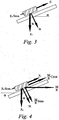
- Each guide 56 has a helical form, with a constant progression axially per cycle (or part cycle, or per degree). This can be considered as a constant angle of progression, ⁇ .
- a female part 502 is generally cup shaped having an annular rim 504 formed integrally with a base 506.
- the interior of the rim is formed with helical guide grooves 508.
- a disc shaped permanent magnet 510 is bonded to the interior surface of the base 506. Radial projections 512 on the exterior of the rim 504 may assist in mounting of the part 502.
- the male part 514 of the fastener comprises a cylindrical core 516, which may be hollowed to reduce weight. At one end of this core 516 is mounted a disc shaped permanent magnet 518, poled so as to attract magnet 510. Conveniently, the magnet 518 is seated in a recess 520 in the core 516. Around this end of the core is formed a helical thread formation 522, shaped to engage with the helical guide grooves 508.
- a disc 524 At the opposite end of the core 520 is provided a disc 524, preferably formed integrally.
- the core carries a U-shaped ring 526 serving as an eye rivet enabling the part 514 to be mounted trough a circular aperture in a flap, lid or other flat work piece.
- the ring 526 is mounted to permit relative rotation of the core 520.
- a bearing is formed with split bearing rings 528, 530; end ring 532 which is recessed into the disc 524 and retaining ring 534.
- Appropriate parts of the bearing, such as the bearing rings 528,530, are usefully formed of PTFE or other low friction material.
- the free end of the male part 514 is brought manually into register with the opening of the female part.
- the force of magnetic attraction is chosen so that the fastener self closes, with the core 516 rotating "automatically” as the two parts of the fastener are magnetically drawn together. Unfastening is achieved by manual rotation of the core by the using holding the disc 524 in the fingers.
- the disc 524 may have a non-circular shape or may have other surface or shape features to improve grip by the fingers.
- fastener has the advantage explained previously that a very strong magnet may be employed, giving improved security.
- the risk of accidental unfastening will be seen to be very low. Nonetheless, the fastener can be unfastened when require, by simple rotation.
- the mechanical advantage afforded by the thread formation is such that relatively low torque can overcome relatively strong magnetic attraction.
- Another advantageous feature is that the rotation of the disc 524, which occurs automatically as the fastener closes, may be visually attractive.
- the exterior of the disc may be designed to enhance this affect. In some examples, formations may be provided which give an audible indication of the relative rotation.
- cufflinks - which may have a high value - are formed in a single part.
- the cufflink is often provided with a hinge or with a flexible link element.
- a single cufflink is formed from two separable parts, considerably simplifying the application of the cufflink to button holes.
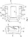
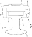
- the cufflink has a male part 610 and a female part 650. It will be seen that the part 610 comprises a plate 612 which may carry a decorative motif applied to its outer face. The inner face of the plate 612 is bonded to or formed integrally with a pillar 614 which carries a base 616. Located within the base 616 is a disc shaped permanent magnet 618. The circumferential surface of base 616 carries three helical or thread-like formations 620.
- the female part 650 of the cufflink is generally cup-shaped and is dimensioned to fit over the base 616.
- Part 650 has a circular base 652, the outer face of which may carry a design feature 654.
- the part 650 further comprises an annular rim 655.
- Three helical grooves 656 are cut into the circumferentially inner surface of the rim 655, the grooves 656 being dimensioned and positioned to engage as a screw thread with the formations 620.
- a disc shaped permanent magnet 658 is embedded in the part 650.
- the standard device can be used to secure a very wide variety of components rapidly in a repeatable manner which is resistant to axial load.
- the device could be used to secure the limbs of a mannequin.
- the arm say would be easily magnetically attached by having the socket end of the device on the arm and the plug end on the torso. This would allow rapid disconnection for dressing the mannequin.
- This technique could also be applied to the attachment of prosthetic devices such as facial prosthetics for the nose ear and eyes.
- prosthetic devices such as facial prosthetics for the nose ear and eyes.
- These are magnetically attached with a plurality of magnets each attached to osteo-integrating screws implanted into the patient's bone.
- the prosthetic device is attached to the plurality of magnets and is held firmly in place by the respective location of the magnets. This, whilst a convenient way to attach the devices, may cause several problems.
- the prosthetic is prone to become detached from the patient, alignment is difficult and many bone screws are used.
- Use of a locking device as described here would offer many benefits, including very firm axial and radial location of the device, natural resistance to being knocked off, reduction of the number of screws required to attach the device for a minimum of three to one.
- fasteners many modifications can be made to the design without departing from the scope of the invention.
- different numbers and different types of helical formations could be employed. It is not necessary for both elements of a screw formation to be helical; a single or multiple pins on one part could engage with a helical groove or projection on the other part to effect relative rotation.
- the pitch of a screw formation may vary along the axis of magnetic attraction.
- a screw thread may have an additional locating feature providing an end or other stop. Whilst two permanent magnets will provide greater force, some application may be best served with a magnet on one part and suitable magnetic material in the other.
- This invention also has application with electromagnets.
- swipe card entry door locks rely on large electromagnets for their operation. It is generally possible to overcome the magnetic force in these door locks reasonably easily and hence they do not provide for high security. Increasing the force requires large magnets and higher currents, which may not always be practical or economic.
- a fixed part 701 carries an electromagnet 702.
- the part 701 carries an internal thread formation comprising a first part 703 which is right-handed and a second portion 704 which is left handed.
- the door mounted part 705 carries pins 706 which engage in the thread formation and also carries a permanent magnet 707.
- One part or other of the fastener (as convenient) is mounted or configured to provide for relative rotation about the axis.
- the electromagnet In the open state, the electromagnet is poled for attraction of the permanent magnet. As the door shuts, the two parts of the device mutually engage, as shown in Figure 8A , the device would auto close under magnetic attraction, with relative rotation between the parts effected through engagement of the pins 706 with the right-handed thread formation.
- the electromagnet When the lock bottoms, as shown in Figure 8B , the electromagnet is arranged to reverse polarity, as shown in Figure 8C , forcing the plug up the left handed thread to a locking feature.
- the electromagnet On swiping of an authorised entry card, the electromagnet is poled the opposite way and the location device is pulled the reverse way down the opposite thread from whence the polarity is reversed again so that the plug is automatically ejected.
- Reversing of the current supplied to the electromagnet on bottoming of the lock can be achieved with a wide variety of electronic or electromechanical devices well known to the skilled reader.
Landscapes
- Engineering & Computer Science (AREA)
- Mechanical Engineering (AREA)
- Textile Engineering (AREA)
- Physics & Mathematics (AREA)
- Electromagnetism (AREA)
- Slide Fasteners, Snap Fasteners, And Hook Fasteners (AREA)
- Connection Of Plates (AREA)
- Magnetic Treatment Devices (AREA)
Claims (3)
- Agrafe comprenant deux parties (10, 50) séparables le long d'un axe de séparation, au moins une partie comprenant un aimant (18, 58) qui établit une force magnétique le long de l'axe de séparation, ainsi qu'un accouplement mécanique qui présente des éléments complémentaires (22, 56) respectivement formés sur les deux parties (10, 50) de l'agrafe, l'accouplement mécanique étant conçu de sorte qu'un déplacement conjoint des deux parties (10, 50) sous l'effet de la force magnétique entraîne une rotation relative automatique des parties (10, 50) autour de l'axe, la force magnétique étant attractive, l'agrafe étant caractérisée en ce que l'accouplement mécanique est tel qu'une rotation relative manuelle des parties (10, 50) offre un avantage mécanique pour surmonter l'attraction magnétique sur la séparation des parties (10, 50) et en ce qu'au moins l'un des éléments complémentaires (22, 56) de l'accouplement mécanique consiste en une formation de vis hélicoïdale autour de l'axe de séparation.
- Agrafe selon la revendication 1, l'angle hélicoïdal de la formation de vis étant α et le coefficient de frottement µf dans l'accouplement mécanique étant sélectionné de sorte que tan-1 (µf) <= α.
- Agrafe selon l'une quelconque des revendications précédentes, chacune des parties présentant un élément de montage, au moins l'une des parties étant agencée pour une rotation relativement à sa partie de montage associée.
Applications Claiming Priority (2)
| Application Number | Priority Date | Filing Date | Title |
|---|---|---|---|
| GB0710953A GB2449906A (en) | 2007-06-07 | 2007-06-07 | Fastener with magnet and mechanical coupling requiring rotation to release |
| PCT/GB2008/001969 WO2008149120A2 (fr) | 2007-06-07 | 2008-06-09 | Agrafe |
Publications (2)
| Publication Number | Publication Date |
|---|---|
| EP2205111A2 EP2205111A2 (fr) | 2010-07-14 |
| EP2205111B1 true EP2205111B1 (fr) | 2017-02-15 |
Family
ID=38318911
Family Applications (1)
| Application Number | Title | Priority Date | Filing Date |
|---|---|---|---|
| EP08762309.6A Not-in-force EP2205111B1 (fr) | 2007-06-07 | 2008-06-09 | Agrafe |
Country Status (4)
| Country | Link |
|---|---|
| US (1) | US8516665B2 (fr) |
| EP (1) | EP2205111B1 (fr) |
| GB (1) | GB2449906A (fr) |
| WO (1) | WO2008149120A2 (fr) |
Families Citing this family (29)
| Publication number | Priority date | Publication date | Assignee | Title |
|---|---|---|---|---|
| DE102008019063B4 (de) * | 2008-04-15 | 2011-04-14 | Fidlock Gmbh | Mechanisch-magnetische Verbindungskonstruktion |
| CA2752390A1 (fr) * | 2009-02-17 | 2010-08-26 | Imdex Technology Australia Pty Ltd | Systeme d'orientation de carotte modulaire |
| US20120153758A1 (en) * | 2009-09-01 | 2012-06-21 | Lloyd George Perry | Pulsating Permanent Magnet Engine |
| DE202010008272U1 (de) * | 2010-08-12 | 2010-10-28 | Messerschmidt, Burkhard | Schmuckgegenstand |
| US8505174B2 (en) * | 2011-01-08 | 2013-08-13 | Dubrosky & Tracy Patent Service Corp. | Fastener for clothing or lingerie |
| US20120240535A1 (en) * | 2011-03-22 | 2012-09-27 | General Electric Company | Filter retaining apparatus |
| NL2008261C2 (nl) * | 2012-02-08 | 2013-08-14 | Gassan Diamonds B V | Sieraad met verwisselbaar decoratief element. |
| US9138624B2 (en) * | 2013-01-09 | 2015-09-22 | Christopher Matthew MAUGHAM | Golf glove magnetic attachment adaptor |
| DE102013213633A1 (de) * | 2013-07-11 | 2015-01-15 | Fidlock Gmbh | Verschlussvorrichtung |
| US10182609B2 (en) * | 2014-07-28 | 2019-01-22 | Speedplay, Inc. | Aperture cover for bicycle cleat assembly |
| JP6774407B2 (ja) * | 2014-11-21 | 2020-10-21 | フィドロック・ゲーエムベーハーFidlock Gmbh | 保持装置に電子機器を固定するための閉鎖装置 |
| KR101625007B1 (ko) * | 2014-12-09 | 2016-05-30 | 주식회사 삼손 | 풀림방지 볼트조립체 |
| US9717293B2 (en) | 2015-06-11 | 2017-08-01 | Michelle P. LIM | Magnetic fastener for a garment |
| DE102015216242A1 (de) * | 2015-08-25 | 2017-03-02 | Fidlock Gmbh | Verschlussvorrichtung zum Befestigen eines Gegenstands an einem Trägerelement |
| US10026535B2 (en) * | 2015-12-31 | 2018-07-17 | Catch Latch, Llc | Mechanical magnetic connector structure |
| US10662686B2 (en) | 2016-09-30 | 2020-05-26 | Barrette Outdoor Living, Inc. | Magnetic safety gate latch |
| IT201700012759A1 (it) * | 2017-02-06 | 2018-08-06 | Metal Ideas Rete Di Imprese | Dispositivo di chiusura ad incastro |
| GB2564137A (en) * | 2017-07-04 | 2019-01-09 | Spotspot Ltd | Surface mounting device |
| US11116264B2 (en) * | 2018-02-14 | 2021-09-14 | Gina Rae Adams | Magnetic button adapter system and method for manufacturing |
| GB2577241A (en) * | 2018-08-02 | 2020-03-25 | Oyebode Akintunde | Detachable accessory |
| EP4275625B1 (fr) * | 2018-08-13 | 2025-03-12 | Bien-Air Holding SA | Système de commande avec bouton stérilisable amovible |
| US20200154832A1 (en) * | 2018-11-18 | 2020-05-21 | Duncan Quinn-Smith | System for Interchangeable Cufflink Faces |
| EP4418953A4 (fr) * | 2021-10-22 | 2025-08-27 | Steven Grabowski | Système de fixation magnétique |
| US12465118B2 (en) * | 2021-10-22 | 2025-11-11 | Steven GRABOWSKI | Magnetic fastener system |
| US12342889B2 (en) | 2022-09-21 | 2025-07-01 | Mast Industries (Far East) Limited | Garment with accessible magnetic closure |
| CN218863002U (zh) * | 2022-09-29 | 2023-04-14 | 邱子游 | 磁吸连接件 |
| DE102022134194B4 (de) * | 2022-12-20 | 2024-06-27 | Fidlock Gmbh | Verschlussvorrichtung mit einem verstellbaren Verbindungselement |
| DE102022134193B4 (de) * | 2022-12-20 | 2024-07-18 | Fidlock Gmbh | Verschlussvorrichtung mit einem verstellbaren Verbindungselement |
| US12312040B2 (en) * | 2023-02-21 | 2025-05-27 | PakBrite LLC | Bicycle underseat storage with light and wheel guard |
Family Cites Families (10)
| Publication number | Priority date | Publication date | Assignee | Title |
|---|---|---|---|---|
| EP0269539A3 (fr) * | 1986-10-29 | 1988-06-15 | Jean-Marie Fritsch | Accouplement rapide dissociable entre une ampoule d'éclairage et sa douille |
| JPH0415055Y2 (fr) * | 1989-10-03 | 1992-04-06 | ||
| JPH09158934A (ja) * | 1995-12-08 | 1997-06-17 | Nisshin:Kk | 磁性を有するナット体 |
| DE19908523A1 (de) * | 1999-02-26 | 2000-08-31 | Wuebker Gmbh J | Schmuckstück mit auswechselbarem Dekorationselement |
| DE19922618C2 (de) * | 1999-05-17 | 2003-06-12 | Robert Bielek | Magneto-mechanischer Schnellverschluß |
| US6363584B1 (en) * | 2000-01-20 | 2002-04-02 | George Gero | Cuff link with changeable element |
| US20030154576A1 (en) * | 2002-02-20 | 2003-08-21 | Eddia Mirharooni | Eddia cuff link |
| ATE556608T1 (de) * | 2003-01-25 | 2012-05-15 | Sheung Chung Wong | Magnetische befestigungsvorrichtung |
| DK200500084U3 (da) * | 2005-04-05 | 2005-06-10 | Jepsen Else Birgitte Stengaard | Kædeafslutning med magneter |
| GB0515910D0 (en) * | 2005-08-02 | 2005-09-07 | Clough Anthony G E | Light bulb |
-
2007
- 2007-06-07 GB GB0710953A patent/GB2449906A/en not_active Withdrawn
-
2008
- 2008-06-09 EP EP08762309.6A patent/EP2205111B1/fr not_active Not-in-force
- 2008-06-09 WO PCT/GB2008/001969 patent/WO2008149120A2/fr not_active Ceased
- 2008-06-09 US US12/663,412 patent/US8516665B2/en active Active
Also Published As
| Publication number | Publication date |
|---|---|
| EP2205111A2 (fr) | 2010-07-14 |
| US20100263173A1 (en) | 2010-10-21 |
| US8516665B2 (en) | 2013-08-27 |
| GB0710953D0 (en) | 2007-07-18 |
| WO2008149120A3 (fr) | 2009-09-24 |
| WO2008149120A2 (fr) | 2008-12-11 |
| GB2449906A (en) | 2008-12-10 |
Similar Documents
| Publication | Publication Date | Title |
|---|---|---|
| EP2205111B1 (fr) | Agrafe | |
| US9974363B2 (en) | Button adapter fastening system | |
| US7207091B2 (en) | Magnetic clasp apparatus | |
| CN102612326B (zh) | 锁合装置 | |
| EP2755521B1 (fr) | Fermeture à glissière à auto-alignement | |
| US6842946B2 (en) | Interchangeable fascia for cabinet knob | |
| EP3753438A1 (fr) | Boucle | |
| EP3305121A1 (fr) | Agencement de sangles | |
| US20050198788A1 (en) | Fastening clip for jewelry, handbags, etc. | |
| WO2007019181A1 (fr) | Fermoir magnetique pour sac a main | |
| CN106413450A (zh) | 磁性按扣紧固件 | |
| US10064441B1 (en) | Locking button system | |
| US5249832A (en) | Magnetized opener/closer for zippers | |
| EP4440363A1 (fr) | Fermeture de sangle de ceinture | |
| US20100242230A1 (en) | Clothing fasteners | |
| CN116104862A (zh) | 与要装入到钩内部中的元件连接的钩 | |
| WO2022203831A1 (fr) | Éléments de fixation magnétiques de verrouillage | |
| US9713354B2 (en) | Twist-lock button | |
| US10327490B2 (en) | Accessory attachment system | |
| CN110319078A (zh) | 紧固系统 | |
| US9080595B1 (en) | Hook with magnetic closure | |
| EP4210533A1 (fr) | Appareil de liaison | |
| EP4426955B1 (fr) | Dispositif de raccordement | |
| US11655082B2 (en) | Container with safety-latch | |
| JP2013017534A (ja) | ロック機構付き留め具、及びそれを備えた製品 |
Legal Events
| Date | Code | Title | Description |
|---|---|---|---|
| PUAI | Public reference made under article 153(3) epc to a published international application that has entered the european phase |
Free format text: ORIGINAL CODE: 0009012 |
|
| 17P | Request for examination filed |
Effective date: 20100415 |
|
| AK | Designated contracting states |
Kind code of ref document: A2 Designated state(s): AT BE BG CH CY CZ DE DK EE ES FI FR GB GR HR HU IE IS IT LI LT LU LV MC MT NL NO PL PT RO SE SI SK TR |
|
| AX | Request for extension of the european patent |
Extension state: AL BA MK RS |
|
| DAX | Request for extension of the european patent (deleted) | ||
| GRAP | Despatch of communication of intention to grant a patent |
Free format text: ORIGINAL CODE: EPIDOSNIGR1 |
|
| RIC1 | Information provided on ipc code assigned before grant |
Ipc: A44B 99/00 20100101ALI20150327BHEP Ipc: A41F 1/00 20060101AFI20150327BHEP Ipc: E05C 5/04 20060101ALI20150327BHEP Ipc: E05C 19/16 20060101ALI20150327BHEP Ipc: A44B 5/02 20060101ALI20150327BHEP |
|
| INTG | Intention to grant announced |
Effective date: 20150421 |
|
| 19U | Interruption of proceedings before grant |
Effective date: 20110421 |
|
| 19W | Proceedings resumed before grant after interruption of proceedings |
Effective date: 20151201 |
|
| RIN1 | Information on inventor provided before grant (corrected) |
Inventor name: SOUTHERN, ANDREW Inventor name: CLARKE, MICHAEL Inventor name: SUTCLIFFE, CHRISTOPHER |
|
| INTG | Intention to grant announced |
Effective date: 20151210 |
|
| RAP1 | Party data changed (applicant data changed or rights of an application transferred) |
Owner name: CLARKE, MICHAEL |
|
| GRAS | Grant fee paid |
Free format text: ORIGINAL CODE: EPIDOSNIGR3 |
|
| RAP1 | Party data changed (applicant data changed or rights of an application transferred) |
Owner name: CLARKE, RYAN Owner name: CLARKE, MICHAEL |
|
| GRAA | (expected) grant |
Free format text: ORIGINAL CODE: 0009210 |
|
| AK | Designated contracting states |
Kind code of ref document: B1 Designated state(s): AT BE BG CH CY CZ DE DK EE ES FI FR GB GR HR HU IE IS IT LI LT LU LV MC MT NL NO PL PT RO SE SI SK TR |
|
| REG | Reference to a national code |
Ref country code: CH Ref legal event code: EP Ref country code: GB Ref legal event code: FG4D |
|
| REG | Reference to a national code |
Ref country code: IE Ref legal event code: FG4D |
|
| REG | Reference to a national code |
Ref country code: AT Ref legal event code: REF Ref document number: 867402 Country of ref document: AT Kind code of ref document: T Effective date: 20170315 |
|
| REG | Reference to a national code |
Ref country code: DE Ref legal event code: R096 Ref document number: 602008048759 Country of ref document: DE |
|
| REG | Reference to a national code |
Ref country code: NL Ref legal event code: MP Effective date: 20170215 |
|
| REG | Reference to a national code |
Ref country code: LT Ref legal event code: MG4D |
|
| REG | Reference to a national code |
Ref country code: AT Ref legal event code: MK05 Ref document number: 867402 Country of ref document: AT Kind code of ref document: T Effective date: 20170215 |
|
| PG25 | Lapsed in a contracting state [announced via postgrant information from national office to epo] |
Ref country code: GR Free format text: LAPSE BECAUSE OF FAILURE TO SUBMIT A TRANSLATION OF THE DESCRIPTION OR TO PAY THE FEE WITHIN THE PRESCRIBED TIME-LIMIT Effective date: 20170516 Ref country code: HR Free format text: LAPSE BECAUSE OF FAILURE TO SUBMIT A TRANSLATION OF THE DESCRIPTION OR TO PAY THE FEE WITHIN THE PRESCRIBED TIME-LIMIT Effective date: 20170215 Ref country code: NO Free format text: LAPSE BECAUSE OF FAILURE TO SUBMIT A TRANSLATION OF THE DESCRIPTION OR TO PAY THE FEE WITHIN THE PRESCRIBED TIME-LIMIT Effective date: 20170515 Ref country code: LT Free format text: LAPSE BECAUSE OF FAILURE TO SUBMIT A TRANSLATION OF THE DESCRIPTION OR TO PAY THE FEE WITHIN THE PRESCRIBED TIME-LIMIT Effective date: 20170215 Ref country code: FI Free format text: LAPSE BECAUSE OF FAILURE TO SUBMIT A TRANSLATION OF THE DESCRIPTION OR TO PAY THE FEE WITHIN THE PRESCRIBED TIME-LIMIT Effective date: 20170215 |
|
| PG25 | Lapsed in a contracting state [announced via postgrant information from national office to epo] |
Ref country code: LV Free format text: LAPSE BECAUSE OF FAILURE TO SUBMIT A TRANSLATION OF THE DESCRIPTION OR TO PAY THE FEE WITHIN THE PRESCRIBED TIME-LIMIT Effective date: 20170215 Ref country code: BG Free format text: LAPSE BECAUSE OF FAILURE TO SUBMIT A TRANSLATION OF THE DESCRIPTION OR TO PAY THE FEE WITHIN THE PRESCRIBED TIME-LIMIT Effective date: 20170515 Ref country code: PT Free format text: LAPSE BECAUSE OF FAILURE TO SUBMIT A TRANSLATION OF THE DESCRIPTION OR TO PAY THE FEE WITHIN THE PRESCRIBED TIME-LIMIT Effective date: 20170615 Ref country code: AT Free format text: LAPSE BECAUSE OF FAILURE TO SUBMIT A TRANSLATION OF THE DESCRIPTION OR TO PAY THE FEE WITHIN THE PRESCRIBED TIME-LIMIT Effective date: 20170215 Ref country code: ES Free format text: LAPSE BECAUSE OF FAILURE TO SUBMIT A TRANSLATION OF THE DESCRIPTION OR TO PAY THE FEE WITHIN THE PRESCRIBED TIME-LIMIT Effective date: 20170215 Ref country code: NL Free format text: LAPSE BECAUSE OF FAILURE TO SUBMIT A TRANSLATION OF THE DESCRIPTION OR TO PAY THE FEE WITHIN THE PRESCRIBED TIME-LIMIT Effective date: 20170215 Ref country code: SE Free format text: LAPSE BECAUSE OF FAILURE TO SUBMIT A TRANSLATION OF THE DESCRIPTION OR TO PAY THE FEE WITHIN THE PRESCRIBED TIME-LIMIT Effective date: 20170215 |
|
| PG25 | Lapsed in a contracting state [announced via postgrant information from national office to epo] |
Ref country code: CZ Free format text: LAPSE BECAUSE OF FAILURE TO SUBMIT A TRANSLATION OF THE DESCRIPTION OR TO PAY THE FEE WITHIN THE PRESCRIBED TIME-LIMIT Effective date: 20170215 Ref country code: RO Free format text: LAPSE BECAUSE OF FAILURE TO SUBMIT A TRANSLATION OF THE DESCRIPTION OR TO PAY THE FEE WITHIN THE PRESCRIBED TIME-LIMIT Effective date: 20170215 Ref country code: EE Free format text: LAPSE BECAUSE OF FAILURE TO SUBMIT A TRANSLATION OF THE DESCRIPTION OR TO PAY THE FEE WITHIN THE PRESCRIBED TIME-LIMIT Effective date: 20170215 Ref country code: SK Free format text: LAPSE BECAUSE OF FAILURE TO SUBMIT A TRANSLATION OF THE DESCRIPTION OR TO PAY THE FEE WITHIN THE PRESCRIBED TIME-LIMIT Effective date: 20170215 Ref country code: IT Free format text: LAPSE BECAUSE OF FAILURE TO SUBMIT A TRANSLATION OF THE DESCRIPTION OR TO PAY THE FEE WITHIN THE PRESCRIBED TIME-LIMIT Effective date: 20170215 |
|
| REG | Reference to a national code |
Ref country code: DE Ref legal event code: R097 Ref document number: 602008048759 Country of ref document: DE |
|
| PG25 | Lapsed in a contracting state [announced via postgrant information from national office to epo] |
Ref country code: PL Free format text: LAPSE BECAUSE OF FAILURE TO SUBMIT A TRANSLATION OF THE DESCRIPTION OR TO PAY THE FEE WITHIN THE PRESCRIBED TIME-LIMIT Effective date: 20170215 Ref country code: DK Free format text: LAPSE BECAUSE OF FAILURE TO SUBMIT A TRANSLATION OF THE DESCRIPTION OR TO PAY THE FEE WITHIN THE PRESCRIBED TIME-LIMIT Effective date: 20170215 |
|
| PLBE | No opposition filed within time limit |
Free format text: ORIGINAL CODE: 0009261 |
|
| STAA | Information on the status of an ep patent application or granted ep patent |
Free format text: STATUS: NO OPPOSITION FILED WITHIN TIME LIMIT |
|
| REG | Reference to a national code |
Ref country code: DE Ref legal event code: R119 Ref document number: 602008048759 Country of ref document: DE |
|
| 26N | No opposition filed |
Effective date: 20171116 |
|
| PG25 | Lapsed in a contracting state [announced via postgrant information from national office to epo] |
Ref country code: MC Free format text: LAPSE BECAUSE OF FAILURE TO SUBMIT A TRANSLATION OF THE DESCRIPTION OR TO PAY THE FEE WITHIN THE PRESCRIBED TIME-LIMIT Effective date: 20170215 |
|
| REG | Reference to a national code |
Ref country code: CH Ref legal event code: PL |
|
| GBPC | Gb: european patent ceased through non-payment of renewal fee |
Effective date: 20170609 |
|
| PG25 | Lapsed in a contracting state [announced via postgrant information from national office to epo] |
Ref country code: SI Free format text: LAPSE BECAUSE OF FAILURE TO SUBMIT A TRANSLATION OF THE DESCRIPTION OR TO PAY THE FEE WITHIN THE PRESCRIBED TIME-LIMIT Effective date: 20170215 |
|
| REG | Reference to a national code |
Ref country code: IE Ref legal event code: MM4A |
|
| REG | Reference to a national code |
Ref country code: FR Ref legal event code: ST Effective date: 20180228 |
|
| PG25 | Lapsed in a contracting state [announced via postgrant information from national office to epo] |
Ref country code: DE Free format text: LAPSE BECAUSE OF NON-PAYMENT OF DUE FEES Effective date: 20180103 Ref country code: GB Free format text: LAPSE BECAUSE OF NON-PAYMENT OF DUE FEES Effective date: 20170609 Ref country code: LI Free format text: LAPSE BECAUSE OF NON-PAYMENT OF DUE FEES Effective date: 20170630 Ref country code: LU Free format text: LAPSE BECAUSE OF NON-PAYMENT OF DUE FEES Effective date: 20170609 Ref country code: CH Free format text: LAPSE BECAUSE OF NON-PAYMENT OF DUE FEES Effective date: 20170630 Ref country code: IE Free format text: LAPSE BECAUSE OF NON-PAYMENT OF DUE FEES Effective date: 20170609 |
|
| PG25 | Lapsed in a contracting state [announced via postgrant information from national office to epo] |
Ref country code: FR Free format text: LAPSE BECAUSE OF NON-PAYMENT OF DUE FEES Effective date: 20170630 |
|
| REG | Reference to a national code |
Ref country code: BE Ref legal event code: MM Effective date: 20170630 |
|
| PG25 | Lapsed in a contracting state [announced via postgrant information from national office to epo] |
Ref country code: BE Free format text: LAPSE BECAUSE OF NON-PAYMENT OF DUE FEES Effective date: 20170630 |
|
| PG25 | Lapsed in a contracting state [announced via postgrant information from national office to epo] |
Ref country code: MT Free format text: LAPSE BECAUSE OF NON-PAYMENT OF DUE FEES Effective date: 20170609 |
|
| PG25 | Lapsed in a contracting state [announced via postgrant information from national office to epo] |
Ref country code: HU Free format text: LAPSE BECAUSE OF FAILURE TO SUBMIT A TRANSLATION OF THE DESCRIPTION OR TO PAY THE FEE WITHIN THE PRESCRIBED TIME-LIMIT; INVALID AB INITIO Effective date: 20080609 |
|
| PG25 | Lapsed in a contracting state [announced via postgrant information from national office to epo] |
Ref country code: CY Free format text: LAPSE BECAUSE OF NON-PAYMENT OF DUE FEES Effective date: 20170215 |
|
| PG25 | Lapsed in a contracting state [announced via postgrant information from national office to epo] |
Ref country code: TR Free format text: LAPSE BECAUSE OF FAILURE TO SUBMIT A TRANSLATION OF THE DESCRIPTION OR TO PAY THE FEE WITHIN THE PRESCRIBED TIME-LIMIT Effective date: 20170215 |
|
| PG25 | Lapsed in a contracting state [announced via postgrant information from national office to epo] |
Ref country code: IS Free format text: LAPSE BECAUSE OF FAILURE TO SUBMIT A TRANSLATION OF THE DESCRIPTION OR TO PAY THE FEE WITHIN THE PRESCRIBED TIME-LIMIT Effective date: 20170615 |