EP2205836B1 - Fluidzufuhrverbindung für reduktionsmittelzuführungseinheit für systeme zur selektiven katalytischen reduktion - Google Patents
Fluidzufuhrverbindung für reduktionsmittelzuführungseinheit für systeme zur selektiven katalytischen reduktion Download PDFInfo
- Publication number
- EP2205836B1 EP2205836B1 EP08767784.5A EP08767784A EP2205836B1 EP 2205836 B1 EP2205836 B1 EP 2205836B1 EP 08767784 A EP08767784 A EP 08767784A EP 2205836 B1 EP2205836 B1 EP 2205836B1
- Authority
- EP
- European Patent Office
- Prior art keywords
- heat shield
- urea solution
- unit
- flange
- supply structure
- Prior art date
- Legal status (The legal status is an assumption and is not a legal conclusion. Google has not performed a legal analysis and makes no representation as to the accuracy of the status listed.)
- Active
Links
Images
Classifications
-
- F—MECHANICAL ENGINEERING; LIGHTING; HEATING; WEAPONS; BLASTING
- F01—MACHINES OR ENGINES IN GENERAL; ENGINE PLANTS IN GENERAL; STEAM ENGINES
- F01N—GAS-FLOW SILENCERS OR EXHAUST APPARATUS FOR MACHINES OR ENGINES IN GENERAL; GAS-FLOW SILENCERS OR EXHAUST APPARATUS FOR INTERNAL-COMBUSTION ENGINES
- F01N3/00—Exhaust or silencing apparatus having means for purifying, rendering innocuous, or otherwise treating exhaust
- F01N3/08—Exhaust or silencing apparatus having means for purifying, rendering innocuous, or otherwise treating exhaust for rendering innocuous
- F01N3/10—Exhaust or silencing apparatus having means for purifying, rendering innocuous, or otherwise treating exhaust for rendering innocuous by thermal or catalytic conversion of noxious components of exhaust
- F01N3/18—Exhaust or silencing apparatus having means for purifying, rendering innocuous, or otherwise treating exhaust for rendering innocuous by thermal or catalytic conversion of noxious components of exhaust characterised by methods of operation; Control
- F01N3/20—Exhaust or silencing apparatus having means for purifying, rendering innocuous, or otherwise treating exhaust for rendering innocuous by thermal or catalytic conversion of noxious components of exhaust characterised by methods of operation; Control specially adapted for catalytic conversion
- F01N3/206—Adding periodically or continuously substances to exhaust gases for promoting purification, e.g. catalytic material in liquid form, NOx reducing agents
- F01N3/2066—Selective catalytic reduction [SCR]
-
- F—MECHANICAL ENGINEERING; LIGHTING; HEATING; WEAPONS; BLASTING
- F01—MACHINES OR ENGINES IN GENERAL; ENGINE PLANTS IN GENERAL; STEAM ENGINES
- F01N—GAS-FLOW SILENCERS OR EXHAUST APPARATUS FOR MACHINES OR ENGINES IN GENERAL; GAS-FLOW SILENCERS OR EXHAUST APPARATUS FOR INTERNAL-COMBUSTION ENGINES
- F01N2530/00—Selection of materials for tubes, chambers or housings
- F01N2530/18—Plastics material, e.g. polyester resin
-
- F—MECHANICAL ENGINEERING; LIGHTING; HEATING; WEAPONS; BLASTING
- F01—MACHINES OR ENGINES IN GENERAL; ENGINE PLANTS IN GENERAL; STEAM ENGINES
- F01N—GAS-FLOW SILENCERS OR EXHAUST APPARATUS FOR MACHINES OR ENGINES IN GENERAL; GAS-FLOW SILENCERS OR EXHAUST APPARATUS FOR INTERNAL-COMBUSTION ENGINES
- F01N2610/00—Adding substances to exhaust gases
- F01N2610/02—Adding substances to exhaust gases the substance being ammonia or urea
-
- F—MECHANICAL ENGINEERING; LIGHTING; HEATING; WEAPONS; BLASTING
- F01—MACHINES OR ENGINES IN GENERAL; ENGINE PLANTS IN GENERAL; STEAM ENGINES
- F01N—GAS-FLOW SILENCERS OR EXHAUST APPARATUS FOR MACHINES OR ENGINES IN GENERAL; GAS-FLOW SILENCERS OR EXHAUST APPARATUS FOR INTERNAL-COMBUSTION ENGINES
- F01N2610/00—Adding substances to exhaust gases
- F01N2610/10—Adding substances to exhaust gases the substance being heated, e.g. by heating tank or supply line of the added substance
-
- F—MECHANICAL ENGINEERING; LIGHTING; HEATING; WEAPONS; BLASTING
- F01—MACHINES OR ENGINES IN GENERAL; ENGINE PLANTS IN GENERAL; STEAM ENGINES
- F01N—GAS-FLOW SILENCERS OR EXHAUST APPARATUS FOR MACHINES OR ENGINES IN GENERAL; GAS-FLOW SILENCERS OR EXHAUST APPARATUS FOR INTERNAL-COMBUSTION ENGINES
- F01N2610/00—Adding substances to exhaust gases
- F01N2610/14—Arrangements for the supply of substances, e.g. conduits
-
- F—MECHANICAL ENGINEERING; LIGHTING; HEATING; WEAPONS; BLASTING
- F01—MACHINES OR ENGINES IN GENERAL; ENGINE PLANTS IN GENERAL; STEAM ENGINES
- F01N—GAS-FLOW SILENCERS OR EXHAUST APPARATUS FOR MACHINES OR ENGINES IN GENERAL; GAS-FLOW SILENCERS OR EXHAUST APPARATUS FOR INTERNAL-COMBUSTION ENGINES
- F01N2610/00—Adding substances to exhaust gases
- F01N2610/14—Arrangements for the supply of substances, e.g. conduits
- F01N2610/1453—Sprayers or atomisers; Arrangement thereof in the exhaust apparatus
-
- Y—GENERAL TAGGING OF NEW TECHNOLOGICAL DEVELOPMENTS; GENERAL TAGGING OF CROSS-SECTIONAL TECHNOLOGIES SPANNING OVER SEVERAL SECTIONS OF THE IPC; TECHNICAL SUBJECTS COVERED BY FORMER USPC CROSS-REFERENCE ART COLLECTIONS [XRACs] AND DIGESTS
- Y02—TECHNOLOGIES OR APPLICATIONS FOR MITIGATION OR ADAPTATION AGAINST CLIMATE CHANGE
- Y02A—TECHNOLOGIES FOR ADAPTATION TO CLIMATE CHANGE
- Y02A50/00—TECHNOLOGIES FOR ADAPTATION TO CLIMATE CHANGE in human health protection, e.g. against extreme weather
- Y02A50/20—Air quality improvement or preservation, e.g. vehicle emission control or emission reduction by using catalytic converters
-
- Y—GENERAL TAGGING OF NEW TECHNOLOGICAL DEVELOPMENTS; GENERAL TAGGING OF CROSS-SECTIONAL TECHNOLOGIES SPANNING OVER SEVERAL SECTIONS OF THE IPC; TECHNICAL SUBJECTS COVERED BY FORMER USPC CROSS-REFERENCE ART COLLECTIONS [XRACs] AND DIGESTS
- Y02—TECHNOLOGIES OR APPLICATIONS FOR MITIGATION OR ADAPTATION AGAINST CLIMATE CHANGE
- Y02T—CLIMATE CHANGE MITIGATION TECHNOLOGIES RELATED TO TRANSPORTATION
- Y02T10/00—Road transport of goods or passengers
- Y02T10/10—Internal combustion engine [ICE] based vehicles
- Y02T10/12—Improving ICE efficiencies
Definitions
- the invention relates to a reductant delivery unit (RDU) that supplies reductant to an engine exhaust system and, more particularly, to an improved fluid supply connection between a Selective Catalytic Reduction (SCR) injection unit and heated supply tube.
- RDU reductant delivery unit
- SCR Selective Catalytic Reduction
- Ammonia is difficult to handle in its pure form in the automotive environment. Therefore, it is customary with these systems to use a liquid aqueous urea solution, typically at a 32% concentration of urea solution (CO (NH 2 ) 2 )
- the solution is referred to as AUS-32, and is also known under its commercial name of AdBlue.
- the urea solution is delivered to the hot exhaust stream and is transformed into ammonia in the exhaust after undergoing thermolysis, or thermal decomposition, into ammonia and isocyanic acid (HNCO).
- HNCO isocyanic acid
- the isocyanic acid then undergoes a hydrolysis with the water present in the exhaust and is transformed into ammonia and carbon dioxide (C02).
- C02 ammonia resulting from the thermolysis and the hydrolysis then undergoes a catalyzed reaction with the nitrogen oxides as described previously.
- the delivery of the AUS-32 solution to the exhaust involves precise metering of the fluid and proper preparation of the fluid to facilitate the later mixing of the ammonia in the exhaust stream.
- the precise metering is typically provided by the use of a low-cost, high volume solenoid injector commonly used in gasoline fuel systems.
- the injector is supplied with AUS-32 via tubing that must be heated due to the relatively high freezing point of -11C of the fluid.
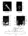
- the tubing interface 10 to the RDU 12 is generally a fluid connection that permits rapid coupling or decoupling of heated tubing (not shown) from the interface 10 for ease of assembly or for servicing.
- the RDU 12 is shown coupled to an exhaust flow path 13.
- the injector side of the connection is then welded or joined to the injector cup 14, into which is placed the injector inlet connector with O-ring 15 providing sealing.
- This connection results in an unheated volume (indicated by dimension A in FIG. 2 ) of fluid that is difficult to reach by the electrical heating element emanating from the tubing, thus increasing thaw times to thaw this volume.
- the metering control is carried out by a Siemens Deka IV injector mounted in a control block.
- the metered fluid is transported via a tube to the exhaust.
- the fluid is also exposed to compressed air to aid with atomization which will ensure subsequent good mixing with the exhaust gas.
- the pressurized mixture is then injected into the exhaust.
- tubes supplying the dosing unit are heated and the system is purged with air at shutdown minimizing the amount of fluid that freezes.
- the fluid connection is made with a standard SAE J2044 quick connect fitting, creating the thawing problem noted above.
- the Bosch production air-assist system also comprises a dosing module with heated supply tubes.
- Bosch has also disclosed a system concept that does not use air. Since air compression is not expected to be available on many future applications of the SCR technology, there is a need to have delivery of the AUS-32 without air-assistance while using a solenoid injector.
- the supply tubes to the injection unit are heated, with the injection unit interface to the fluid supply tubes employing the SAE J2044 quick connect fittings, creating the thawing problem noted above.
- WO 2003/039718 A1 concerns a method and a device for reducing nitrogen oxides in exhaust gases, in particular in a motor vehicle exhaust gases.
- the method is characterized in that it consists in introducing an aqueous urea solution in a reactor and converting it by thermal, catalytic or enzymatic treatment into a decomposition product containing ammonia and carbon dioxide, the ammonia being added to the exhaust gases.
- the aqueous urea solution contains a substance for heat transmission and for lowering freezing point.
- the device includes a tank for the aqueous urea solution.
- a pump is connected downstream of tank, via which the aqueous urea solution including the substance is conveyed into a helical reactor.
- the reactor is situated in an exhaust system of a motor vehicle having a diesel engine. Using the exhaust gas, it is thus possible to heat the urea solution including the substance for transferring heat and for lowering the freezing point to a temperature higher than 180°C. Downstream of reactor, a line leads out of exhaust system to a heat exchanger. The decomposition product heated in reactor designed as a helical pipe is cooled in heat exchanger so that a downstream metering valve again leading into exhaust system is protected against thermal damage.
- WO 2006/050547 A1 relates to a device for transforming or removing nitrogen oxides of an exhaust gas, comprising: a storage reservoir for storing a reducing agent, particularly a solution such as a urea/water solution or an ammonia solution; a delivery means connected to the storage reservoir; a dosing means connected downstream from the delivery means, and; a reaction chamber for purifying the exhaust gas, for example, an exhaust gas tract of a motor vehicle.
- the delivery means enable the reducing agent to be delivered to the dosing means and to be introduced via this dosing means into the reaction chamber.
- the invention provides that the dosing means is provided in the form of a valve that is directly connected to the reaction chamber while projecting therein.
- DE 10241698 A1 discloses an exhaust emission control device mounted in an exhaust pipe for an diesel engine for injecting a reducer to the upstream side of a NOx catalyst.
- the device has a functioning part consisting of an opening/closing valve and driving means for driving the opening/closing valve, the functioning part being constructed separately from a housing connector and a housing body of a holding and mounting part as well as a nozzle part.
- the exhaust emission control device is mounted suitable to the construction and configuration of the applicable engine without changing the shape of the functioning part.
- the reductant delivery unit includes a solenoid fluid injector constructed and arranged to be associated with an exhaust gas flow path upstream of a SCR catalytic converter.
- the fluid injector has a fluid inlet and a fluid outlet. The fluid inlet being constructed and arranged to receive a source of urea solution and the fluid outlet being constructed and arranged to communicate directly with the exhaust flow path so as to control injection of urea solution into the exhaust gas flow path.
- Supply structure defines the fluid inlet.
- the supply structure includes a portion coupled to a body of the injector and a supply tube integral with the cup to define a single member.
- the supply tube is constructed and arranged to be coupled with the source of urea solution to deliver urea solution to the fluid inlet.
- the supply tube is constructed and arranged to be heated by a heat source so that an entire volume of the urea solution delivered to the fluid inlet is heated.
- the unit further comprises, according to the invention, a heat shield substantially surrounding the injector.
- a method ensures that urea solution provided to a reductant delivery unit (RDU) for selective catalytic reduction (SCR) after-treatment for vehicles is heated.
- the RDU is mounted with respect to an exhaust gas flow path so as to inject urea solution directly into the exhaust gas flow path.
- the method provides supply structure defining a fluid inlet of the RDU.
- the supply structure includes a supply tube integral with a portion of the RDU so as to define a single member.
- the supply tube is coupled with the source of urea solution to deliver urea solution to the fluid inlet.
- the supply tube is heated so that an entire volume of the urea solution delivered to the fluid inlet of the RDU is heated.
- the method further comprises, according to the invention, providing a heat shield to substantially surround the injector.
- a reductant delivery unit for the delivery of AUS-32 to the engine exhaust is shown, generally indicated at 16, in accordance with an embodiment of the invention.
- the RDU 16 is used in SCR exhaust after-treatment systems on vehicles.
- the metering function of the RDU 16 is performed by a specially adapted and packaged solenoid fluid injector 18.
- the injector 18 also provides the spray preparation of the fluid in the exhaust path 13 that is upstream of an SCR catalytic converter 20 ( FIG. 5 ). More particularly, a flange 22 of the RDU 16 with injector 18 is mounted on a boss 24 of the exhaust path 13 preferably between an oxygen catalytic converter 26 and the SCR catalytic converter 20.
- the fluid injector 18 is preferably a gasoline, electrically operated, solenoid fluid injector such as the type disclosed in U.S. Patent No 6,685,112 and co-pending U.S. Application No. 12/078,252, filed on March 28, 2008 .
- the injector 18 also has a fluid inlet 28 and a fuel outlet 30 that extends through the flange 24.
- the inlet 28 receives a source of urea solution or AUS-32 via a supply tube 29 from a tank 27 ( FIG. 5 ).
- the fluid outlet 30 communicates with the exhaust flow path 13 so the solution can be injected directly into the exhaust flow path 13.
- Power is provided to the injector 18 at electrical connector 23.
- the injector 18 controls the flow rate of AUS-32 into the exhaust flow path 13 and also shuts-off the flow.
- the supply tube 29 is made integral with a supply structure 32, generally indicated at 32, of the injector 18.
- the supply structure 32 defines the fluid inlet 28 of the injector 18.
- a heat source 33 heats the entire supply tube 29 so that an entire volume of the urea solution delivered to the inlet 28 of the injector 18 is heated. Therefore, this configuration provides an advantage over the conventional RDU 12 of FIG. 2 since no time is needed to thaw fluid that would otherwise freeze in the unheated volume A of FIG. 2 .
- the supply structure 32 preferably molded of plastic, includes an integral flange 35, from which the integral supply tube 29 extends, and an integral cup 37 that is sealed with respect to the injector body 41 via an O-ring 39.
- the flange 35 can be considered to be part of the cup 37.
- the supply structure 32 is mechanically joined to the RDU 16. In the embodiment, this mechanical coupling is achieved by providing multiple flexible tangs 34 extending from the flange 35.
- the tangs 34 are defined during molding of the supply structure 32.
- Each tang 34 passes through opening 36 in a heat shield 38 of the RDU 16 and engages a surface 40 of the heat shield 38 at a first end 42 thereof.
- the heat shield 38 is generally cylindrical having an open end 42.
- the flange 35 closes the open end 42.
- the heat shield is constructed and arranged to substantially surround the injector 18 with the other, opposing end 44 of the heat shield 38 being coupled with the flange 22 that mounts to the boss 24.
- access openings to access the tangs 34 are provided in the heat shield 38 for a tool to push the tangs 34 back toward the openings 36.
- other removable securing means can be used such as, for example, bolts, clips, snap fits, etc.
Landscapes
- Chemical & Material Sciences (AREA)
- Engineering & Computer Science (AREA)
- Chemical Kinetics & Catalysis (AREA)
- Health & Medical Sciences (AREA)
- Toxicology (AREA)
- Combustion & Propulsion (AREA)
- Mechanical Engineering (AREA)
- General Engineering & Computer Science (AREA)
- Exhaust Gas After Treatment (AREA)
Claims (12)
- Reduktionsmittelzuführeinheit (16) für die Nachbehandlung mittels selektiver katalytischer Reduktion (SCR) in Fahrzeugen, wobei die Reduktionsmittelzuführeinheit (16) umfasst:eine Solenoidfluideinspritzdüse (18), die zur Verbindung mit einem Abgasströmungsweg (13) vorgeordnet zu einem SCR-Katalysator (20) konstruiert und angeordnet ist, wobei die Fluideinspritzdüse (18) einen Fluideinlass (28) und einen Fluidauslass (30) aufweist, wobei der Fluideinlass (28) zum Empfangen einer Quelle für Harnstofflösung konstruiert und angeordnet ist und der Fluidauslass (30) zum direkten Kommunizieren mit dem Abgasströmungsweg (13) konstruiert und angeordnet ist, um so das Einspritzen der Harnstofflösung in den Abgasströmungsweg (13) zu steuern, undeine Einspeisestruktur (32), die den Fluideinlass (28) definiert, wobei die Einspeisestruktur (32) einen Abschnitt (37), der an den Körper der Einspritzdüse (18) gekoppelt ist, und ein Einspeiserohr (29) umfasst, wobei das Einspeiserohr (29) zur Kopplung mit der Quelle für Harnstofflösung konstruiert und angeordnet ist, um dem Fluideinlass (28) Harnstofflösung zuzuführen,wobei das Einspeiserohr (29) zum Erwärmen durch eine Wärmequelle (33) konstruiert und angeordnet ist, so dass ein gesamtes Volumen der dem Fluideinlass (28) zugeführten Harnstofflösung erwärmt wird,
dadurch gekennzeichnet, dass
das Einspeiserohr (29) integral mit dem Abschnitt (37) ist, um ein Einzelelement zu definieren, und
die Einheit ferner einen Hitzeschild (38) umfasst, der die Einspritzdüse (18) im Wesentlichen umgibt, wobei die Einspeisestruktur (29) mit dem Hitzeschild (38) in Verbindung steht. - Einheit (16) nach Anspruch 1, wobei die Einspeisestruktur (32) einen integralen Flansch (35) einschließt, wobei das Einspeiserohr (29) integral mit dem Flansch (35) ist und sich von dem Flansch (35) aus erstreckt, wobei der Flansch (35) zum entfernbaren Koppeln an den Hitzeschild (38) konstruiert und angeordnet ist.
- Einheit (16) nach Anspruch 2, wobei der Flansch (35) Mittel zum entfernbaren Befestigen des Flansches (35) an einem Ende des Hitzeschilds (38) einschließt.
- Einheit (16) nach Anspruch 2 oder 3, wobei der Flansch (35) eine Vielzahl sich aus ihm erstreckender flexibler Griffzungen (34) einschließt, ein Ende des Hitzeschilds (38) eine Vielzahl von Öffnungen (36) einschließt, eine Griffzunge (34) in einer damit verbundenen Öffnung (36) aufgenommen wird, wobei die Griffzungen (34) in eine Oberfläche (40) des Hitzeschilds (38) eingreifen, um die Einspeisestruktur (32) entfernbar an dem Hitzeschild (38) zu befestigen.
- Einheit (16) nach Anspruch 1 oder 2, wobei die Einspeisestruktur (32) aus Kunststoff geformt ist.
- Einheit (16) nach Anspruch 2, wobei der Hitzeschild (38) allgemein zylindrisch mit einem offenen Ende (42) ist, wobei der Flansch (35) das offene Ende (42) verschließt.
- Einheit nach Anspruch 4, wobei der Hitzeschild (38) allgemein zylindrisch mit einem offenen Ende (42) ist, wobei der Flansch (35) das offene Ende (42) verschließt, und wobei der Hitzeschild (38) Öffnungen (36) einschließt, die zum Zugang der Griffzungen (34) konstruiert und angeordnet sind.
- Einheit (16) nach Anspruch 1, wobei der Hitzeschild (38) gegenüberliegende Enden (42, 44) aufweist, wobei ein Abschnitt der Einspeisestruktur (32) an eines der Enden (42) gekoppelt ist, und ein Flansch (22), der zum Koppeln an den Abgasströmungsweg (13) konstruiert und angeordnet ist, an das andere Ende (44) gekoppelt ist.
- Einheit (16) nach Anspruch 1 in Kombination mit einem Heizer (33), der das gesamte Einspeiserohr erwärmt.
- Einheit (16) nach einem der vorhergehenden Ansprüche, wobei der Abschnitt (37) eine Schale ist.
- Verfahren zum Sicherstellen, dass Harnstofflösung, die einer Reduktionsmittelzuführeinheit (RDU) (16) zur Nachbehandlung mittels selektiver katalytischer Reduktion (SCR) für Fahrzeuge bereitgestellt wird, erwärmt wird, wobei die RDU (16) in Bezug auf einen Abgasströmungsweg (13) derart montiert ist, dass Harnstofflösung direkt in den Abgasströmungsweg (13) eingespritzt wird, wobei das Verfahren umfasst:Bereitstellen von Einspeisestruktur (32), die einen Fluideinlass (28) der RDU (16) definiert, wobei die Einspeisestruktur (32) ein Einspeiserohr (29) einschließt, das integral mit einem Abschnitt der RDU (16) ist, um so ein Einzelelement zu definieren, wobei das Einspeiserohr (29) mit der Quelle für Harnstofflösung gekoppelt ist, um dem Fluideinlass (28) Harnstofflösung zuzuführen,Bereitstellen eines Hitzeschilds (38), der die Einspritzdüse (16) im Wesentlichen umgibt, undKoppeln der Einspeisestruktur (32) an den Hitzeschild (38) in entfernbarer Weise, undErwärmen des Einspeiserohrs (29), so dass ein gesamtes Volumen der dem Fluideinlass (28) der RDU (16) zugeführten Harnstofflösung erwärmt wird.
- Verfahren nach Anspruch 11, wobei der Schritt des Bereitstellens der Einspeisestruktur (32) Formen der Einspeisestruktur (32) aus Kunststoff einschließt.
Applications Claiming Priority (2)
| Application Number | Priority Date | Filing Date | Title |
|---|---|---|---|
| US98253107P | 2007-10-25 | 2007-10-25 | |
| PCT/US2008/006351 WO2009054865A1 (en) | 2007-10-25 | 2008-05-16 | Fluid supply connection for reductant delivery unit for selective catalytic reduction systems |
Publications (2)
| Publication Number | Publication Date |
|---|---|
| EP2205836A1 EP2205836A1 (de) | 2010-07-14 |
| EP2205836B1 true EP2205836B1 (de) | 2016-10-19 |
Family
ID=39689503
Family Applications (1)
| Application Number | Title | Priority Date | Filing Date |
|---|---|---|---|
| EP08767784.5A Active EP2205836B1 (de) | 2007-10-25 | 2008-05-16 | Fluidzufuhrverbindung für reduktionsmittelzuführungseinheit für systeme zur selektiven katalytischen reduktion |
Country Status (4)
| Country | Link |
|---|---|
| US (1) | US8087239B2 (de) |
| EP (1) | EP2205836B1 (de) |
| JP (1) | JP5091324B2 (de) |
| WO (1) | WO2009054865A1 (de) |
Families Citing this family (35)
| Publication number | Priority date | Publication date | Assignee | Title |
|---|---|---|---|---|
| DE102008038984A1 (de) * | 2008-08-13 | 2010-02-18 | Emitec Gesellschaft Für Emissionstechnologie Mbh | Verfahren zum selektiven Beheizen einer Reduktionsmittelleitung |
| DE102009048514A1 (de) * | 2009-10-07 | 2011-04-14 | Emitec Gesellschaft Für Emissionstechnologie Mbh | Injektorhalterung |
| US8240137B2 (en) * | 2009-10-27 | 2012-08-14 | Cummins Filtration Ip, Inc. | Reductant injection and decomposition system |
| US8429903B2 (en) * | 2009-12-22 | 2013-04-30 | Caterpillar Inc. | Radial mounting for regeneration device |
| EP2339138A1 (de) * | 2009-12-24 | 2011-06-29 | Inergy Automotive Systems Research (Société Anonyme) | Mit einem Heizelement ausgerüsteter Flansch |
| BR112012031838B1 (pt) | 2010-06-15 | 2020-12-08 | Shaw Development, Llc | combinação e unidade de cabeçote |
| US8822887B2 (en) | 2010-10-27 | 2014-09-02 | Shaw Arrow Development, LLC | Multi-mode heater for a diesel emission fluid tank |
| US8756921B2 (en) * | 2011-01-10 | 2014-06-24 | Paccar Inc | Reductant delivery device |
| US9115624B2 (en) * | 2011-07-29 | 2015-08-25 | Continental Automotive Systems, Inc. | Anti-rotation structure for a valve installed in an exhaust boss of a reductant delivery system |
| WO2013112154A1 (en) * | 2012-01-26 | 2013-08-01 | International Engine Intellectual Property Company, Llc | Injector boss and system and method of injecting liquid into a gas stream |
| DE102012004727A1 (de) * | 2012-03-07 | 2013-09-12 | Emitec Gesellschaft Für Emissionstechnologie Mbh | Vorrichtung zur Bereitstellung von flüssigem Additiv |
| US9416709B2 (en) * | 2012-06-15 | 2016-08-16 | Continental Automotive Systems, Inc. | Coking resistant after-treatment dosing value |
| US9777859B2 (en) * | 2012-11-19 | 2017-10-03 | Continental Automotive Systems, Inc. | Purging and sealing-reductant delivery unit for selective catalytic reduction systems |
| US9341295B2 (en) * | 2013-03-27 | 2016-05-17 | Cummins Emission Solutions, Inc. | Fluid connectors for reductant systems |
| US8997463B2 (en) | 2013-04-17 | 2015-04-07 | Continental Automotive Systems, Inc. | Reductant delivery unit for automotive selective catalytic reduction with reducing agent heating |
| US9366167B2 (en) * | 2013-11-08 | 2016-06-14 | Continental Automotive Systems, Inc. | Injector water intrusion seal with blow out volume |
| USD729141S1 (en) | 2014-05-28 | 2015-05-12 | Shaw Development LLC | Diesel emissions fluid tank |
| USD729722S1 (en) | 2014-05-28 | 2015-05-19 | Shaw Development LLC | Diesel emissions fluid tank floor |
| FR3022582B1 (fr) * | 2014-06-19 | 2016-07-01 | Peugeot Citroen Automobiles Sa | Systeme de reduction selective catalytique muni d'un insert caloduc sur son injecteur |
| DE102015006517A1 (de) | 2015-04-01 | 2016-10-06 | Cummins Emission Solutions Inc. | Ventilmagnetschalter |
| US9714598B2 (en) | 2015-04-30 | 2017-07-25 | Faurecia Emissions Control Technologies, Usa, Llc | Mixer with integrated doser cone |
| US9719397B2 (en) | 2015-04-30 | 2017-08-01 | Faurecia Emissions Control Technologies Usa, Llc | Mixer with integrated doser cone |
| US9726064B2 (en) | 2015-04-30 | 2017-08-08 | Faurecia Emissions Control Technologies, Usa, Llc | Mixer for use in a vehicle exhaust system |
| US9828897B2 (en) * | 2015-04-30 | 2017-11-28 | Faurecia Emissions Control Technologies Usa, Llc | Mixer for a vehicle exhaust system |
| DE102015217673A1 (de) | 2015-09-15 | 2017-03-16 | Continental Automotive Gmbh | Einspritzvorrichtung zur Zumessung eines Fluids und Kraftfahrzeug mit einer derartigen Einspritzvorrichtung |
| WO2018075061A1 (en) | 2016-10-21 | 2018-04-26 | Faurecia Emissions Control Technologies Usa, Llc | Reducing agent mixer |
| FR3069280A1 (fr) * | 2017-07-18 | 2019-01-25 | Psa Automobiles Sa | Systeme de reduction selective catalytique muni d'un dispositif de protection thermique |
| US10502112B2 (en) * | 2017-09-14 | 2019-12-10 | Vitesco Technologies USA, LLC | Injector for reductant delivery unit having fluid volume reduction assembly |
| US10539057B2 (en) * | 2017-09-14 | 2020-01-21 | Vitesco Technologies USA, LLC | Injector for reductant delivery unit having reduced fluid volume |
| US10947880B2 (en) | 2018-02-01 | 2021-03-16 | Continental Powertrain USA, LLC | Injector for reductant delivery unit having fluid volume reduction assembly |
| US10287948B1 (en) | 2018-04-23 | 2019-05-14 | Faurecia Emissions Control Technologies, Usa, Llc | High efficiency mixer for vehicle exhaust system |
| US10316721B1 (en) | 2018-04-23 | 2019-06-11 | Faurecia Emissions Control Technologies, Usa, Llc | High efficiency mixer for vehicle exhaust system |
| US10787946B2 (en) | 2018-09-19 | 2020-09-29 | Faurecia Emissions Control Technologies, Usa, Llc | Heated dosing mixer |
| US10767533B1 (en) | 2019-02-28 | 2020-09-08 | Tenneco Automotive Operating Company Inc. | Reagent injector |
| WO2024006240A1 (en) * | 2022-06-28 | 2024-01-04 | Cummins Emission Solutions Inc. | Doser mount for exhaust aftertreatment system |
Family Cites Families (26)
| Publication number | Priority date | Publication date | Assignee | Title |
|---|---|---|---|---|
| EP0458368B1 (de) * | 1984-04-02 | 1997-02-26 | Hitachi, Ltd. | Sauerstoffsensor |
| US4742964A (en) * | 1985-10-30 | 1988-05-10 | Aisan Kogyo Kabushiki Kaisha | Electromagnetic fuel injector |
| JPH0199981U (de) * | 1987-12-25 | 1989-07-05 | ||
| US5224343A (en) * | 1990-02-22 | 1993-07-06 | Erno Raumfahrttechnik Gmbh | Constant fuel supply device for a thruster |
| NL1003980C2 (nl) * | 1996-09-06 | 1998-03-13 | Vialle Beheer B V | Inspuitinrichting. |
| DE19726392A1 (de) * | 1997-06-21 | 1998-12-24 | Bosch Gmbh Robert | Gemischabgabevorrichtung |
| DE19739435A1 (de) * | 1997-09-09 | 1999-03-11 | Bosch Gmbh Robert | Meßfühler |
| US6047907A (en) | 1997-12-23 | 2000-04-11 | Siemens Automotive Corporation | Ball valve fuel injector |
| JP2000027627A (ja) * | 1998-07-13 | 2000-01-25 | Hino Motors Ltd | 排気ガス浄化触媒用還元剤保温装置及びそれを組込んだ排気ガス浄化装置 |
| US6526746B1 (en) * | 2000-08-02 | 2003-03-04 | Ford Global Technologies, Inc. | On-board reductant delivery assembly |
| US6481420B2 (en) * | 2001-01-30 | 2002-11-19 | Visteon Global Technologies, Inc. | Method and apparatus for maintaining the alignment of a fuel injector |
| JP3888518B2 (ja) | 2001-09-10 | 2007-03-07 | 株式会社デンソー | 排気浄化装置 |
| US6913210B2 (en) * | 2001-09-28 | 2005-07-05 | Holley Performance Products | Fuel injector nozzle adapter |
| DE10154421A1 (de) | 2001-11-06 | 2003-05-22 | Bosch Gmbh Robert | Verfahren und Vorrichtung zur Verminderung von Stickoxiden eines Abgases |
| US6814303B2 (en) * | 2002-04-03 | 2004-11-09 | Cleaire Advanced Emission Controls | Fluid-cooled mount for an injector |
| US6996976B2 (en) * | 2002-04-03 | 2006-02-14 | Cleaire Advanced Emmision Controls | Apparatus and method for mounting a device to a pipe |
| JP4262522B2 (ja) * | 2003-05-28 | 2009-05-13 | 株式会社日立ハイテクノロジーズ | エンジン用排気ガス処理装置および排気ガス処理方法 |
| BRPI0411322A (pt) * | 2003-06-12 | 2006-07-18 | Donaldson Co Inc | método de distribuir combustìvel em fluxo transiente de um sistema de descarga |
| US7614213B2 (en) * | 2003-09-19 | 2009-11-10 | Nissan Diesel Motor Co., Ltd. | Engine exhaust emission purification apparatus |
| FR2874075B1 (fr) | 2004-08-03 | 2007-11-09 | Espa Sarl | Tube de transport de fluide |
| US20060101810A1 (en) * | 2004-11-15 | 2006-05-18 | Angelo Theodore G | System for dispensing fuel into an exhaust system of a diesel engine |
| AT501091B1 (de) | 2004-11-15 | 2006-12-15 | Pankl Emission Control Systems | Abgasreinigungsvorrichtung |
| DE102004056791B4 (de) | 2004-11-24 | 2007-04-19 | J. Eberspächer GmbH & Co. KG | Abgasanlage |
| JP2007113403A (ja) * | 2005-10-18 | 2007-05-10 | Nissan Diesel Motor Co Ltd | 外気温度検出装置及び排気浄化装置 |
| FR2897644B1 (fr) | 2006-02-20 | 2011-08-05 | Renault Sas | Dispositif de depollution des gaz d'echappement d'un moteur a combustion interne |
| DE102006058402A1 (de) * | 2006-12-12 | 2008-06-19 | Bayerische Motoren Werke Ag | Vorrichtung zum Zumischen eines Reduktionsmittels in einen Abgasstrom einer Brennkraftmaschine |
-
2008
- 2008-05-16 JP JP2010530990A patent/JP5091324B2/ja active Active
- 2008-05-16 EP EP08767784.5A patent/EP2205836B1/de active Active
- 2008-05-16 WO PCT/US2008/006351 patent/WO2009054865A1/en not_active Ceased
- 2008-05-16 US US12/153,353 patent/US8087239B2/en not_active Expired - Fee Related
Also Published As
| Publication number | Publication date |
|---|---|
| JP2011501042A (ja) | 2011-01-06 |
| WO2009054865A1 (en) | 2009-04-30 |
| JP5091324B2 (ja) | 2012-12-05 |
| US8087239B2 (en) | 2012-01-03 |
| EP2205836A1 (de) | 2010-07-14 |
| US20090107126A1 (en) | 2009-04-30 |
Similar Documents
| Publication | Publication Date | Title |
|---|---|---|
| EP2205836B1 (de) | Fluidzufuhrverbindung für reduktionsmittelzuführungseinheit für systeme zur selektiven katalytischen reduktion | |
| CN104105853B (zh) | 带有冻结适应结构的选择性催化还原的还原剂输送单元 | |
| US8997463B2 (en) | Reductant delivery unit for automotive selective catalytic reduction with reducing agent heating | |
| EP2134939B1 (de) | Reduktionsmittelabgabeeinheit für selektive katalytische reduktion | |
| KR102309229B1 (ko) | 내연기관 | |
| US9689293B2 (en) | Reductant delivery unit for automotive selective catalytic reduction with optimized fluid heating | |
| US9273581B2 (en) | Purge system for reductant delivery unit for a selective catalytic reduction system | |
| CN104074576B (zh) | 还原系统的流体连接器 | |
| US9074511B2 (en) | Reductant delivery unit for SCR systems having improved deposit resistance | |
| US12460566B2 (en) | Dosing module for use in aftertreatment systems for internal combustion engines | |
| WO2007099372A1 (en) | Ammonia precursor conversion reactor | |
| CN108301905B (zh) | 氨气尿素双喷射系统及其控制方法 | |
| EP3500741B1 (de) | Kompakter seitlicher einlassstutzen einer reduktionsmittelzuführeinheit | |
| WO2021021127A1 (en) | Systems and methods for decreasing time to reach light-off temperature | |
| KR20250008947A (ko) | 배기 가스용 도관 조립체 |
Legal Events
| Date | Code | Title | Description |
|---|---|---|---|
| PUAI | Public reference made under article 153(3) epc to a published international application that has entered the european phase |
Free format text: ORIGINAL CODE: 0009012 |
|
| 17P | Request for examination filed |
Effective date: 20100525 |
|
| AK | Designated contracting states |
Kind code of ref document: A1 Designated state(s): AT BE BG CH CY CZ DE DK EE ES FI FR GB GR HR HU IE IS IT LI LT LU LV MC MT NL NO PL PT RO SE SI SK TR |
|
| AX | Request for extension of the european patent |
Extension state: AL BA MK RS |
|
| DAX | Request for extension of the european patent (deleted) | ||
| RAP1 | Party data changed (applicant data changed or rights of an application transferred) |
Owner name: CONTINENTAL AUTOMOTIVE SYSTEMS US, INC. |
|
| 17Q | First examination report despatched |
Effective date: 20150603 |
|
| RAP1 | Party data changed (applicant data changed or rights of an application transferred) |
Owner name: CONTINENTAL AUTOMOTIVE SYSTEMS, INC. |
|
| GRAP | Despatch of communication of intention to grant a patent |
Free format text: ORIGINAL CODE: EPIDOSNIGR1 |
|
| INTG | Intention to grant announced |
Effective date: 20160510 |
|
| GRAS | Grant fee paid |
Free format text: ORIGINAL CODE: EPIDOSNIGR3 |
|
| GRAA | (expected) grant |
Free format text: ORIGINAL CODE: 0009210 |
|
| AK | Designated contracting states |
Kind code of ref document: B1 Designated state(s): AT BE BG CH CY CZ DE DK EE ES FI FR GB GR HR HU IE IS IT LI LT LU LV MC MT NL NO PL PT RO SE SI SK TR |
|
| REG | Reference to a national code |
Ref country code: GB Ref legal event code: FG4D |
|
| REG | Reference to a national code |
Ref country code: CH Ref legal event code: EP |
|
| REG | Reference to a national code |
Ref country code: AT Ref legal event code: REF Ref document number: 838549 Country of ref document: AT Kind code of ref document: T Effective date: 20161115 |
|
| REG | Reference to a national code |
Ref country code: IE Ref legal event code: FG4D |
|
| REG | Reference to a national code |
Ref country code: DE Ref legal event code: R096 Ref document number: 602008046923 Country of ref document: DE |
|
| REG | Reference to a national code |
Ref country code: NL Ref legal event code: MP Effective date: 20161019 |
|
| REG | Reference to a national code |
Ref country code: LT Ref legal event code: MG4D |
|
| PG25 | Lapsed in a contracting state [announced via postgrant information from national office to epo] |
Ref country code: LV Free format text: LAPSE BECAUSE OF FAILURE TO SUBMIT A TRANSLATION OF THE DESCRIPTION OR TO PAY THE FEE WITHIN THE PRESCRIBED TIME-LIMIT Effective date: 20161019 |
|
| REG | Reference to a national code |
Ref country code: AT Ref legal event code: MK05 Ref document number: 838549 Country of ref document: AT Kind code of ref document: T Effective date: 20161019 |
|
| PG25 | Lapsed in a contracting state [announced via postgrant information from national office to epo] |
Ref country code: LT Free format text: LAPSE BECAUSE OF FAILURE TO SUBMIT A TRANSLATION OF THE DESCRIPTION OR TO PAY THE FEE WITHIN THE PRESCRIBED TIME-LIMIT Effective date: 20161019 Ref country code: NO Free format text: LAPSE BECAUSE OF FAILURE TO SUBMIT A TRANSLATION OF THE DESCRIPTION OR TO PAY THE FEE WITHIN THE PRESCRIBED TIME-LIMIT Effective date: 20170119 Ref country code: SE Free format text: LAPSE BECAUSE OF FAILURE TO SUBMIT A TRANSLATION OF THE DESCRIPTION OR TO PAY THE FEE WITHIN THE PRESCRIBED TIME-LIMIT Effective date: 20161019 Ref country code: GR Free format text: LAPSE BECAUSE OF FAILURE TO SUBMIT A TRANSLATION OF THE DESCRIPTION OR TO PAY THE FEE WITHIN THE PRESCRIBED TIME-LIMIT Effective date: 20170120 |
|
| REG | Reference to a national code |
Ref country code: FR Ref legal event code: PLFP Year of fee payment: 10 |
|
| PG25 | Lapsed in a contracting state [announced via postgrant information from national office to epo] |
Ref country code: AT Free format text: LAPSE BECAUSE OF FAILURE TO SUBMIT A TRANSLATION OF THE DESCRIPTION OR TO PAY THE FEE WITHIN THE PRESCRIBED TIME-LIMIT Effective date: 20161019 Ref country code: HR Free format text: LAPSE BECAUSE OF FAILURE TO SUBMIT A TRANSLATION OF THE DESCRIPTION OR TO PAY THE FEE WITHIN THE PRESCRIBED TIME-LIMIT Effective date: 20161019 Ref country code: IS Free format text: LAPSE BECAUSE OF FAILURE TO SUBMIT A TRANSLATION OF THE DESCRIPTION OR TO PAY THE FEE WITHIN THE PRESCRIBED TIME-LIMIT Effective date: 20170219 Ref country code: NL Free format text: LAPSE BECAUSE OF FAILURE TO SUBMIT A TRANSLATION OF THE DESCRIPTION OR TO PAY THE FEE WITHIN THE PRESCRIBED TIME-LIMIT Effective date: 20161019 Ref country code: PT Free format text: LAPSE BECAUSE OF FAILURE TO SUBMIT A TRANSLATION OF THE DESCRIPTION OR TO PAY THE FEE WITHIN THE PRESCRIBED TIME-LIMIT Effective date: 20170220 Ref country code: PL Free format text: LAPSE BECAUSE OF FAILURE TO SUBMIT A TRANSLATION OF THE DESCRIPTION OR TO PAY THE FEE WITHIN THE PRESCRIBED TIME-LIMIT Effective date: 20161019 Ref country code: BE Free format text: LAPSE BECAUSE OF FAILURE TO SUBMIT A TRANSLATION OF THE DESCRIPTION OR TO PAY THE FEE WITHIN THE PRESCRIBED TIME-LIMIT Effective date: 20161019 Ref country code: ES Free format text: LAPSE BECAUSE OF FAILURE TO SUBMIT A TRANSLATION OF THE DESCRIPTION OR TO PAY THE FEE WITHIN THE PRESCRIBED TIME-LIMIT Effective date: 20161019 Ref country code: FI Free format text: LAPSE BECAUSE OF FAILURE TO SUBMIT A TRANSLATION OF THE DESCRIPTION OR TO PAY THE FEE WITHIN THE PRESCRIBED TIME-LIMIT Effective date: 20161019 |
|
| REG | Reference to a national code |
Ref country code: DE Ref legal event code: R097 Ref document number: 602008046923 Country of ref document: DE |
|
| PG25 | Lapsed in a contracting state [announced via postgrant information from national office to epo] |
Ref country code: DK Free format text: LAPSE BECAUSE OF FAILURE TO SUBMIT A TRANSLATION OF THE DESCRIPTION OR TO PAY THE FEE WITHIN THE PRESCRIBED TIME-LIMIT Effective date: 20161019 Ref country code: SK Free format text: LAPSE BECAUSE OF FAILURE TO SUBMIT A TRANSLATION OF THE DESCRIPTION OR TO PAY THE FEE WITHIN THE PRESCRIBED TIME-LIMIT Effective date: 20161019 Ref country code: EE Free format text: LAPSE BECAUSE OF FAILURE TO SUBMIT A TRANSLATION OF THE DESCRIPTION OR TO PAY THE FEE WITHIN THE PRESCRIBED TIME-LIMIT Effective date: 20161019 Ref country code: RO Free format text: LAPSE BECAUSE OF FAILURE TO SUBMIT A TRANSLATION OF THE DESCRIPTION OR TO PAY THE FEE WITHIN THE PRESCRIBED TIME-LIMIT Effective date: 20161019 Ref country code: CZ Free format text: LAPSE BECAUSE OF FAILURE TO SUBMIT A TRANSLATION OF THE DESCRIPTION OR TO PAY THE FEE WITHIN THE PRESCRIBED TIME-LIMIT Effective date: 20161019 |
|
| PLBE | No opposition filed within time limit |
Free format text: ORIGINAL CODE: 0009261 |
|
| STAA | Information on the status of an ep patent application or granted ep patent |
Free format text: STATUS: NO OPPOSITION FILED WITHIN TIME LIMIT |
|
| PG25 | Lapsed in a contracting state [announced via postgrant information from national office to epo] |
Ref country code: BG Free format text: LAPSE BECAUSE OF FAILURE TO SUBMIT A TRANSLATION OF THE DESCRIPTION OR TO PAY THE FEE WITHIN THE PRESCRIBED TIME-LIMIT Effective date: 20170119 Ref country code: LU Free format text: LAPSE BECAUSE OF NON-PAYMENT OF DUE FEES Effective date: 20170531 |
|
| 26N | No opposition filed |
Effective date: 20170720 |
|
| PG25 | Lapsed in a contracting state [announced via postgrant information from national office to epo] |
Ref country code: SI Free format text: LAPSE BECAUSE OF FAILURE TO SUBMIT A TRANSLATION OF THE DESCRIPTION OR TO PAY THE FEE WITHIN THE PRESCRIBED TIME-LIMIT Effective date: 20161019 |
|
| REG | Reference to a national code |
Ref country code: CH Ref legal event code: PL |
|
| GBPC | Gb: european patent ceased through non-payment of renewal fee |
Effective date: 20170516 |
|
| PG25 | Lapsed in a contracting state [announced via postgrant information from national office to epo] |
Ref country code: MC Free format text: LAPSE BECAUSE OF FAILURE TO SUBMIT A TRANSLATION OF THE DESCRIPTION OR TO PAY THE FEE WITHIN THE PRESCRIBED TIME-LIMIT Effective date: 20161019 |
|
| REG | Reference to a national code |
Ref country code: IE Ref legal event code: MM4A |
|
| PG25 | Lapsed in a contracting state [announced via postgrant information from national office to epo] |
Ref country code: CH Free format text: LAPSE BECAUSE OF NON-PAYMENT OF DUE FEES Effective date: 20170531 Ref country code: LI Free format text: LAPSE BECAUSE OF NON-PAYMENT OF DUE FEES Effective date: 20170531 |
|
| PG25 | Lapsed in a contracting state [announced via postgrant information from national office to epo] |
Ref country code: LU Free format text: LAPSE BECAUSE OF NON-PAYMENT OF DUE FEES Effective date: 20170516 |
|
| PG25 | Lapsed in a contracting state [announced via postgrant information from national office to epo] |
Ref country code: IE Free format text: LAPSE BECAUSE OF NON-PAYMENT OF DUE FEES Effective date: 20170516 Ref country code: GB Free format text: LAPSE BECAUSE OF NON-PAYMENT OF DUE FEES Effective date: 20170516 |
|
| REG | Reference to a national code |
Ref country code: FR Ref legal event code: PLFP Year of fee payment: 11 |
|
| PG25 | Lapsed in a contracting state [announced via postgrant information from national office to epo] |
Ref country code: MT Free format text: LAPSE BECAUSE OF NON-PAYMENT OF DUE FEES Effective date: 20170516 |
|
| PG25 | Lapsed in a contracting state [announced via postgrant information from national office to epo] |
Ref country code: HU Free format text: LAPSE BECAUSE OF FAILURE TO SUBMIT A TRANSLATION OF THE DESCRIPTION OR TO PAY THE FEE WITHIN THE PRESCRIBED TIME-LIMIT; INVALID AB INITIO Effective date: 20080516 |
|
| PGFP | Annual fee paid to national office [announced via postgrant information from national office to epo] |
Ref country code: DE Payment date: 20190531 Year of fee payment: 12 |
|
| PG25 | Lapsed in a contracting state [announced via postgrant information from national office to epo] |
Ref country code: CY Free format text: LAPSE BECAUSE OF NON-PAYMENT OF DUE FEES Effective date: 20161019 |
|
| PG25 | Lapsed in a contracting state [announced via postgrant information from national office to epo] |
Ref country code: TR Free format text: LAPSE BECAUSE OF FAILURE TO SUBMIT A TRANSLATION OF THE DESCRIPTION OR TO PAY THE FEE WITHIN THE PRESCRIBED TIME-LIMIT Effective date: 20161019 |
|
| REG | Reference to a national code |
Ref country code: DE Ref legal event code: R119 Ref document number: 602008046923 Country of ref document: DE |
|
| PG25 | Lapsed in a contracting state [announced via postgrant information from national office to epo] |
Ref country code: DE Free format text: LAPSE BECAUSE OF NON-PAYMENT OF DUE FEES Effective date: 20201201 |
|
| P01 | Opt-out of the competence of the unified patent court (upc) registered |
Effective date: 20230530 |
|
| PGFP | Annual fee paid to national office [announced via postgrant information from national office to epo] |
Ref country code: IT Payment date: 20250527 Year of fee payment: 18 |
|
| PGFP | Annual fee paid to national office [announced via postgrant information from national office to epo] |
Ref country code: FR Payment date: 20250528 Year of fee payment: 18 |