EP2205906B1 - Vorrichtung zur erzeugung einer luftwand - Google Patents
Vorrichtung zur erzeugung einer luftwand Download PDFInfo
- Publication number
- EP2205906B1 EP2205906B1 EP08839106A EP08839106A EP2205906B1 EP 2205906 B1 EP2205906 B1 EP 2205906B1 EP 08839106 A EP08839106 A EP 08839106A EP 08839106 A EP08839106 A EP 08839106A EP 2205906 B1 EP2205906 B1 EP 2205906B1
- Authority
- EP
- European Patent Office
- Prior art keywords
- primary
- air
- blower
- slit
- air stream
- Prior art date
- Legal status (The legal status is an assumption and is not a legal conclusion. Google has not performed a legal analysis and makes no representation as to the accuracy of the status listed.)
- Active
Links
Images


Classifications
-
- F—MECHANICAL ENGINEERING; LIGHTING; HEATING; WEAPONS; BLASTING
- F24—HEATING; RANGES; VENTILATING
- F24F—AIR-CONDITIONING; AIR-HUMIDIFICATION; VENTILATION; USE OF AIR CURRENTS FOR SCREENING
- F24F9/00—Use of air currents for screening, e.g. air curtains
-
- F—MECHANICAL ENGINEERING; LIGHTING; HEATING; WEAPONS; BLASTING
- F24—HEATING; RANGES; VENTILATING
- F24F—AIR-CONDITIONING; AIR-HUMIDIFICATION; VENTILATION; USE OF AIR CURRENTS FOR SCREENING
- F24F8/00—Treatment, e.g. purification, of air supplied to human living or working spaces otherwise than by heating, cooling, humidifying or drying
- F24F8/90—Cleaning of purification apparatus
Definitions
- the invention relates to a device for generating an air wall for thermal separation of the air in a first relatively cold space from the air in a second relatively warm space, which spaces are mutually connected by a passage opening, the device comprising:
- Such an air wall is generally known and usual, for instance for thermal separation of the cold air in a cold store from the relatively warm air in a space connecting thereto, for instance the outside air.
- Such a device is often embodied such that transport vehicles, for instance fork-lift trucks or other means of transport, are able to pass through.
- the primary blower slit can for instance be positioned on one side of a usually rectangular passage opening.
- a blower slit which connects to the upper edge of the opening. In both cases vehicles can travel across the floor and pass through the air wall without obstruction.
- a device of the type stated in the preamble is for instance known from US-A-6 106 387 .
- This document describes a technique which cannot prevent the formation of mist in the passage opening and icing on, among other parts, the floor of the cold store. Both phenomena can result in hazardous situations.
- the known device is not very effective. In the case of for instance a cold store with a temperature of -20°C a temperature of 25°C must for instance be bridged relative to the temperature of +5°C in the outside space. This involves the prerequisite of a high degree of sealing of the passage opening by the air wall. The device according to this American patent cannot meet this requirement of practically complete sealing of the air wall.
- a device as described in US-A-3 143 952 also has the stated drawbacks.
- the invention provides a device of the type stated in the preamble, having the features recited in claim 1, and a corresponding method as described in claim 9.
- a great advantage of the air wall device according to the invention is that the air stream, which is very thin compared to the prior art and which has a high flow speed, effectively has a high degree of "stiffness". Owing to the high momentum content of this flow it is therefore not easy to disrupt the flow. In known air walls or air curtains a flow can easily be displaced out of its nominal path, for instance by suddenly occurring pressure differences as can occur in the case of varying wind loads on the associated outer wall. As a result the highly undesirable phenomenon can occur that the air wall no longer acts to seal the passage opening, or at least does so in greatly worsened manner. This can effectively result in misting, icing on floors, a higher energy consumption and a dramatically reduced quality of the air wall in general. Owing to the property of the air wall according to the invention referred to as "stiffness" this undesirable phenomenon of the air wall being blown away will occur considerably less.
- the infeed pressure in the primary blower slit is considerably higher than that according to the prior art, and that the flow speed of the air will thereby be substantially higher. Since the width of the blower air slit will however be substantially smaller than that according to the prior art, the overall airflow according to the invention is smaller. It is therefore possible to conclude that, using very simple means according to the invention, the efficiency, also the thermal efficiency, of the device according to the invention is better than that according to the prior art.
- the device according to the invention has the special feature that the primary blower unit comprises a cavity to which the primary blower slit connects.
- this embodiment has the special feature that the cavity has an at least more or less prismatic form, i.e. a form having the same cross-sectional form at any axial position.
- the device can be particularly embodied such that the cross-sectional area of the cavity lies in the range of about 400 cm 2 for relatively low airflow speeds to about 2000 cm 2 for relatively high airflow speeds.
- the cavity has a form such that turbulences are essentially prevented.
- Use can be made for this purpose of an at least slightly smooth, rounded form.
- Use can also be made of a form in which the dimensions in two independent directions are roughly in the same order of magnitude, or a faceted form in which the angle between adjacent facets amounts to at least 90°.
- the cavity can in all probability be deemed a pressure buffer into which air under pressure is admitted, the air under pressure is distributed and subsequently blown out through the relatively narrow blower slit.
- the device still more preferably has the special feature that the speed of the air in the primary air stream amounts to at least 30 m/s.
- the device has the feature that the width of the primary blower slit lies in the range of 18-30 mm.
- the device according to the invention comprises a suction unit positioned on the opposite side of the passage opening and having a for instance substantially prismatic suction slit extending substantially parallel to the blower slit and having substantially the same length as the primary blower slit, to which suction slit connect suction fan means. It is noted that such a suction unit with suction slit is per se known from the two stated references.
- a practical embodiment has the special feature that the primary blower slit is connected via a duct to the suction slit, in which duct fan means are disposed which are both the primary blower fan means and the suction fan means. It is noted that this structure is per se known from the two stated publications. Not known however is the specific choice of the relationships between the temperatures and the absolute humidities in the primary air stream and the secondary air flow.
- an air curtain device is known from DE-A-199 32 708 in which use is made of air speeds of an air curtain flow of 5-35 m/s. It is however deemed essential according to the invention that the width of the primary blower slit lies in the range of 15-40 mm, preferably of 18-30 mm, and the length of the primary blower slit in the direction of the air stream lies roughly in the range of 5-40 cm and preferably roughly in the range of 10-30 cm. This significant dimensioning is not known from the stated reference.
- Very simple is an embodiment in which at least one of the secondary air streams is an entrained air stream.
- At least one of the secondary air streams is actively generated by a secondary blower unit with secondary blower fan means and a secondary blower slit which connects thereto on the blower side, is disposed adjacently of the primary blower slit and has substantially the same length as the primary blower slit.
- NL-C-1024346 discloses a device for generating an air curtain comprising a primary air stream and two flanking, secondary air streams, likewise with no mention of any further characterizing part of the present invention.
- condensation and icing may for instance occur.
- use can be made of an embodiment in which the temperature and/or the humidity of the air blown out by a secondary blower unit is changed.
- An embodiment with a primary blower slit and a secondary blower slit is preferably embodied such that the primary blower slit and the secondary blower slit have a mutual distance of a maximum of about 3 mm, preferably 2 mm.
- the device has the special feature that the suction slit has a width and is disposed such that it suctions substantially only the primary air stream Sp.
- the or each secondary air stream remains situated only in the relevant space or the outside air.
- the effectiveness of the air wall according to the invention is hereby not affected, although the efficiency of the device is hereby maintained at a high level.
- the device has the special feature that a catching unit for ice crystals is placed in the downstream zone of the primary outflow.
- the catching unit comprises a filter with gauze, the mesh width of which amounts for instance to 0.4-2 mm, preferably 0.6-1.4 mm.
- the device can be embodied such that the filter is disposed at least more or less vertically and a cleaning device is added to the filter, for instance a brushing device or an impact excitation device, through activation of which the filter undergoes an impact, for instance in its main plane, whereby the ice accumulated against the filter releases from the filter.
- a cleaning device is added to the filter, for instance a brushing device or an impact excitation device, through activation of which the filter undergoes an impact, for instance in its main plane, whereby the ice accumulated against the filter releases from the filter.
- the air curtain according to the invention completely seals and keeps sealed the passage opening, certainly in stationary, relatively calm conditions.
- the lowest part of the air stream must be prevented from undergoing a speed reduction, due to the divergent character inherent thereto, such that there is a danger that the air in this lowest zone begins to move upward in a path which is to some extent curved, thereby creating a non-sealed corner.
- this phenomenon will not take on dramatic forms, although it is nevertheless recommended according to the invention that it be at least substantially wholly precluded.
- the invention provides a device in which a row of control valves, distributed along the height and for instance of the passive type, is added to a vertical suction slit for a substantially constantly passing airflow such that the same flow passes at each height position, such that the air in the relevant air stream flows substantially horizontally at any height.
- Passive control valves which ensure that the passing airflow is always constant are per se known and are commercially available from, among others, the French firms Aldes and Enjos.
- the device is embodied as a generally tubular, hollow portal, with the general form of a downward opening U which can be added or has been added to the passage opening and the one leg of which has a blower slit and the other leg a suction slit.
- a device of this type is suitable for adding to an existing entrance opening. With such a device an existing cold store for instance can therefore be provided with an air wall device according to the invention.
- a practical and simple embodiment of this latter type has the special feature that fan means are present in the hollow portal in the air circuit between the slits.
- the device with a cavity present in the primary blower unit is preferably embodied such that the blower slit connects to the cavity present in the blower unit via a for instance substantially prismatic, narrowing transition zone.
- a cavity can also be used for at least one secondary air stream.
- the blower units for the primary and the secondary air streams can have largely the same construction. Depending on the desired setting, the dimensioning between the primary and the secondary units can also differ to some extent.
- An embodiment with a suction unit preferably has the special feature that the suction slit connects to a suction opening which has a form narrowing from the outside to the inside.
- the device has the feature that on the side remote from the primary blower unit a second, for instance substantially prismatic blower unit is positioned which has a height roughly corresponding to the height of passing vehicles, which second blower unit is set into operation when a vehicle approaches and which is rendered inoperative after the vehicle has wholly passed through the area of the passage opening.
- a second, for instance substantially prismatic blower unit is positioned which has a height roughly corresponding to the height of passing vehicles, which second blower unit is set into operation when a vehicle approaches and which is rendered inoperative after the vehicle has wholly passed through the area of the passage opening.
- the device has the feature that filter means for cleaning suctioned air are added to the suction unit.
- the device can have the special feature that the width of a blower slit is adjustable.
- the invention relates to an assembly of at least two devices in accordance with any of the above described aspects according to the invention, which assembly is disposed in a transit tunnel which connects sealingly to the passage opening, in which assembly adjacent primary air streams have opposing directions.
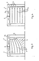
- Figure 1 shows a cold store 1 with an internal temperature in the order of -20°C.
- the outside temperature i.e. the temperature of the ambient air, amounts in this example to about 5°C. There is thus a difference in temperature of 25°C between the air in the cold store and the outside air.
- a device 3 for generating an air wall 4 is added to a passage opening 2.
- This air wall which will be described in more detail hereinbelow, comprises an at least more or less flat air stream which extends in a vertical plane and which moves in the drawing from the left-hand side of device 3 to the right-hand side of device. 3.
- the relatively warm outside air is effectively separated from the cold inside air by this air stream, which has a substantial speed, i.e. a speed of at least 15 m/s, or more than 50 km/h. This separation relates to all relevant properties of the inside air and the outside air, in particular temperature and humidity.
- Figure 2A-1 shows device 3 in more detail.
- the device comprises a primary blower unit 5 positioned on one side of the passage opening and having a primary blower fan 6, which fulfils an additional function in the manner to be described hereinbelow, and a primary blower slit 7 which connects thereto on the blower side, is arranged substantially parallel to the main plane of passage opening 2 and extends over at least substantially the whole height of passage opening 2 for the purpose of generating the air stream, which is indicated with arrows 8 and forms air wall 4, this air stream being directed at the other side of passage opening 2.
- the primary blower unit 5 comprises a cavity 9 which connects via a duct 10 to fan 6, to which cavity the primary blower slit 7 connects.
- This slit has a width 33 of 10-30 mm and a length 34 of 20-40 cm in the direction of primary air flow 8.
- cavity 9 and the primary blower slit 7 have an at least more or less prismatic form.
- suction unit 11 Situated on the other side of passage opening 2 is a suction unit 11 with a suction slit 12, which in this embodiment is substantially prismatic. Suction slit 12 also connects to fan 6 via a second duct 13. There is therefore, as indicated with arrows 24 which show the air streams, a more or less closed circuit in portal 15, of which air stream 8 and thereby air wall 4 form part, and which is wholly generated and sustained by fan 6. Added to suction slit 12 are a number of passive control valves 14 which are uniformly distributed along the height such that the same air stream passes through at each height position. As a result the air in air stream 8 flows substantially horizontally at any height. Arrows 8 indicate this.
- Figure 2A-2 shows the cross-section II-II of figure 2A-1 .
- FIG. 2B shows a variant in which a heating unit 16 is also accommodated in the portal 15 in which fan 6 is placed.
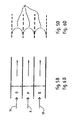
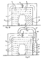
- Figure 3 shows a schematic view of device 3 which, in contrast to the embodiment according to figure 2A , is not provided with the passive control valves 14 for ensuring a constant airflow.
- air wall 4' has a defect, i.e. an open space at the bottom right-hand side. This space is designated with 17. This is because the lowest part of air stream 8' has a strong tendency to move upward.
- figure 4 shows that air flow 8 moves substantially wholly horizontally as a result of the action of the constant flow valves 14.
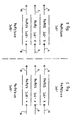
- Figures 5 and 6 show schematically the configuration and parameter values in air wall 4.
- This comprises primary air stream 8 with a temperature of about -5°C and an absolute humidity of 0.5 g/kg.
- This primary air stream 8 is heated relative to the internal space of cold store 1, which does after all have a temperature of -20°C, by the operation of heating unit 16.
- the cold secondary air stream 18 is situated on the inner side, has a temperature of -20°C and an absolute humidity of 0.5 g/kg.
- This secondary air stream logically has the same temperature and humidity as the inside air in the cold store, it being after all an entrained air stream which has not been subjected in any way to any treatment or other intervention.
- the warm secondary air stream 19 This has the same temperature and absolute humidity as the ambient air, i.e. + 5°C and 5.5 g/kg.
- Figures 5A and 6A show what the differences are.
- the invention has for its object to operate the device such that possible formation of vapour occurs only after the other side of passage opening 2 has been passed through.
- the air speed can be adjusted, in particular increased in the case of formation of vapour, or the absolute humidity at the flow of -5°C can be reduced.
- Secondary air streams o 18 and q 19 are the flanking, entrained air streams as shown in figures 5C and 6C .
- Figures 5D and 6D show very schematically a possible speed distribution 35.
- a single air wall 4 has a certain strength for keeping the air masses in the adjacent spaces separated from each other.
- Figure 6 shows another embodiment in which primary air stream 8 has a different humidity, 2 g/kg. This value lies between the corresponding values of air streams 18 and 19.
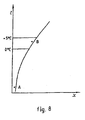
- Figure 7 is a Mollier diagram which shows that, when warm air and cold air with substantially the same relative humidity mix, the saturation limit is passed and condensation such as misting and/or icing occurs.
- Figure 8 shows the same diagram in the situation where no mixing occurs. It is apparent that the occurrence of condensation is prevented in this situation.
- Figure 9 shows the schematic view of figure 4 in slightly more detail.
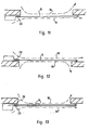
- Figure 10 shows that the air wall 8 from blower slit 20 (given a slightly different form in this embodiment) displays a certain divergence.
- suction slit 21 has an outward widening form whereby the divergent primary air stream 8 can also be wholly taken up.
- Figure 11 shows an embodiment in which use is made of a primary blower unit which generates a primary air stream on the outside.
- Figure 12 shows an embodiment in which a primary blower unit generates an air flow on the inside.
- Figure 13 shows an embodiment in which a primary blower unit generates two primary air streams 8.
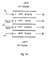
- Figure 14 shows the properties of the four air streams 18, 8, 8, 19, given the fact that in this embodiment the inside temperature of the cold store amounts to -25°C and the ambient temperature to +20°C.
- Figure 14A is the elucidation with Mollier diagram of figure 14 . In this respect reference is also made to figure 6A . No condensation occurs.
- Figure 14B corresponds with figure 5C .
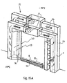
- Figure 15A shows an assembly 25 of two devices 3, 26. Reference is made to figure 3 , which shows one such device 3.
- the width 37 of an added secondary blower slit 36 is greater than that of the primary blower slit 33.
- the embodiment according to figure 15B differs from that of figure 15A in that assembly 25 comprises two devices 3' and 26', in which respective heating units 16, 27 are added to the air circuit.
- Figure 16 shows an embodiment in which the relatively warm secondary air stream 19 is blown out through a secondary blower slit 36, which forms part of a secondary blower unit 39 which also heats the passing air stream.
- FIG 17 shows an embodiment in which the relatively cold secondary air stream 18 is collected by a secondary suction unit 40 which is provided along its height with secondary control valves 14 for a constant flow.
- a secondary suction unit 40 which is provided along its height with secondary control valves 14 for a constant flow.
- a variable degree of opening For the purpose of optimal suction of the secondary air stream 18 use is made of a variable degree of opening. This is realized by a strip 41 which extends in vertical direction and which is connected to the secondary suction unit via a hinge 42. The angular position 43 of strip 41 can thus be adjusted in the drawn manner.
- a heating unit 16 is added to fan 6 in the "cold circuit” 24.
- a cooling unit 45 is added to a fan 44 in the "warm circuit” 24'.
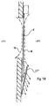
- FIGS 18 and 19 show a further development of the embodiment according to figure 12 .
- a catching unit 127 for ice crystals is added to the device.
- This catching unit 127 comprises a filter with gauze, the mesh width of which lies in the order of 1 mm.
- catching unit 127 can for instance be subjected at regular intervals to an impact excitation, or use can be made of a brushing device. Such provisions are not drawn. They can operate automatically, for instance at regular intervals.
- Figure 20 shows schematically that air wall 4 is seriously disrupted when a vehicle 28 passes through passage opening 2.
- the air present in the right-hand zone 38 relative to vehicle 28 is in this embodiment on the leeward side and the air wall is there no longer effective. Zone 38 can thus be deemed a dead zone or leeward zone.
- Figure 21 shows a variant with which this is obviated.
- a second blower unit 29 Positioned in this embodiment on the side of the suction unit is a second blower unit 29, the height of which roughly corresponds to the height of passing vehicles 28.
- This second blower unit 29 is set into operation by timely advance automatic opening of a valve 46 in a branch duct 47 for the purpose of admitting a partial flow 48 as a vehicle 28 approaches, and is rendered inoperative again once vehicle 28 has wholly passed through the area of passage opening 2. It will be apparent from figure 21 that the air stream is brought about in dead zone 38 by the operation of second blower unit 29, whereby air wall 4 remains at least substantially sealed.
- Figure 22 shows a cold store 1' with an inside temperature of -25°C, wherein the outside temperature amounts for instance to +10°C. In respect of the great temperature difference to be bridged, use is made of an assembly 30 of two devices 3.
- Figure 23 shows a highly schematic cross-section through assembly 31 according to figure 22B .
- assembly 31 comprises three devices 3, the middle device of which has a blow-in direction which is opposite to that of the other two devices. Vortex-like secondary air streams 18, 19 and 19, 18 respectively are thus generated in the cells bounded by the relevant primary air streams 8, 8, 8.
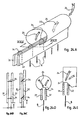
- Figure 24 shows that, by making use of two mutually displaceable strips 31, 32, the distance between these strips 31, 32 can be varied, whereby the width of the primary or secondary blower slit can be changed.
- strips 31, 32 connect airtightly to a flexible, subdivided blower tube 33.
- Figures 24B and 24C show particularly the manner in which, due to hinge connections 34, strips 31, 32 are displaceable parallel to each other and their mutual distance can vary.
- Figures 25A and 25B show a variant.
Landscapes
- Engineering & Computer Science (AREA)
- Chemical & Material Sciences (AREA)
- Combustion & Propulsion (AREA)
- Mechanical Engineering (AREA)
- General Engineering & Computer Science (AREA)
- Ventilation (AREA)
- Structures Of Non-Positive Displacement Pumps (AREA)
Claims (13)
- Vorrichtung (3) zur Erzeugung einer Luftwand (4) zur thermischen Trennung der Luft in einem ersten, relativ kalten Raum von der Luft in einem zweiten, relativ warmen Raum, welche Räume durch eine Durchgangsöffnung (2) miteinander verbunden sind, wobei die Vorrichtung (3) aufweist:eine primäre Gebläseeinheit (5), geeignet zum Positioniertsein auf einer Seite der Durchgangsöffnung (2) im Wesentlichen parallel zur Hauptebene derDurchgangsöffnung (2) und sich Erstrecken über die ganze relevante Abmessung der Durchgangsöffnung (2), wobei die primäre Gebläseeinheit (5) aufweist eine Primärgebläse-Ventilatoreinrichtung (6) und einen Primärgebläseschlitz (7), der sich daran auf der Gebläseseite anschließt, geeignet angeordnet zum Erzeugen eines wenigstens mehr oderweniger flachen, wenigstens annähernd zur gegenüberliegenden Seite der Durchgangsöffnung (2) gerichteten primären Luftstroms (8), undwobei die Primärgebläse-Ventilatoreinrichtung (6) geeignet ist zum Erzeugen einer Luftgeschwindigkeit im primären Luftstrom (8) von wenigstens 15 m/s unddie Breite des Primärgebläseschlitzes (7) im Bereich von 15 bis 40 mm liegt,dadurch gekennzeichnet, dass die Vorrichtung (3) weiter aufweist eine Saugeinheit (11), geeignet zum Positioniertsein auf der gegenüberliegenden Seite der Durchgangsöffnung und Aufweisen eines sich im Wesentlichen parallel zum Gebläseschlitz (7) erstreckenden und im Wesentlichen die gleiche Länge wie der Primärgebläseschlitz (7) aufweisenden Saugschlitzes (12), an welchen Saugschlitz (12) sich eine Saug-Ventilatoreinrichtung (6) anschließt, wobei dem Saugschlitz (12) eine Reihe von Steuerventilen (14) hinzugefügt ist, welche Steuerventile (14) entlang der Erstreckung des Saugschlitzes (12) verteilt sind, um einen im Wesentlichen konstant durchgehenden Luftstrom zu erhalten,und dass die Länge des Primärgebläseschlitzes (7) in der Richtung des Luftstroms annähernd im Bereich von 5 bis 40 cm liegt.
- Vorrichtung (3) nach Anspruch 1, wobei die primäre Gebläseeinheit (5) einen Hohlraum (9) aufweist, an den sich der Primärgebläseschlitz (7) anschließt, und wobei die Querschnittsfläche des Hohlraums (9) im Bereich von etwa 400 cm2 für relativ niedrige Luftstromgeschwindigkeiten bis etwa 2000 cm2 für relativ hohe Luftstromgeschwindigkeiten liegt.
- Vorrichtung (3) nach Anspruch 1, wobei der Primärgebläseschlitz (7) über einen Kanal (13) mit dem Saugschlitz (12) verbunden ist, in welchem Kanal eine Ventilatoreinrichtung (6) angeordnet ist, die sowohl die Primärgebläse-Ventilatoreinrichtung als auch die Saug-Ventilatoreinrichtung ist.
- Vorrichtung (3) nach einem der vorhergehenden Ansprüche, weiter aufweisend eine sekundäre Gebläseeinheit (39) mit einer Sekundärgebläse-Ventilatoreinrichtung und einem Sekundärgebläseschlitz (36), der sich daran auf der Gebläseseite anschließt, angeordnet neben dem Primärgebläseschlitz und im Wesentlichen die gleiche Länge wie der Primärgebläseschlitz aufweisend, und eine Heizeinheit (16), angeordnet zum Ändern einer Temperatur von durch den Sekundärgebläseschlitz (36) herausgeblasener Luft.
- Vorrichtung (3) nach Anspruch 1, wobei eine Fangeinheit (127) für Eiskristalle in der stromabwärtigen Zone der primären Ausströmung platziert ist.
- Vorrichtung (3) nach einem der vorhergehenden Ansprüche, wobei die Vorrichtung (3) als ein generell rohrförmiges, hohles Portal (15) mit der generellen Form eines offenen U, beispielsweise eines abwärts sich öffnenden U verkörpert ist, das der Durchgangsöffnung (2) hinzugefügt werden kann oder hinzugefügt worden ist und dessen einer Schenkel einen Gebläseschlitz (7) und dessen anderer Schenkel einen Saugschlitz (12) aufweist.
- Vorrichtung nach Anspruch 6, wobei die Ventilatoreinrichtung (6) im hohlen Portal (15) im Luftkreislauf (24) zwischen den Schlitzen (7, 12) präsent ist.
- Anordnung (30) aus wenigstens zwei Vorrichtungen (3) nach einem der vorhergehenden Ansprüche, welche Anordnung (30) in einem Transittunnel angeordnet ist, der die Durchgangsöffnung (2) dichtend anschließt, in welcher Anordnung (30) benachbarte primäre Luftströme (8) entgegengesetzte Richtungen aufweisen.
- Verfahren zur Erzeugung einer Luftwand (4) zur thermischen Trennung der Luft in einem ersten, relativ kalten Raum (1) von der Luft in einem zweiten, relativ warmen Raum, welche Räume durch eine Durchgangsöffnung (2) miteinander verbunden sind, wobei das Verfahren aufweist:mit einer primären Gebläseeinheit (5), positioniert auf einer Seite der Durchgangsöffnung (2) und aufweisend eine Primärgebläse-Ventilatoreinrichtung (6) und einen Primärgebläseschlitz (7), der sich daran auf der Gebläseseite anschließt, wobei die primäre Gebläseeinheit (5) im Wesentlichen parallel zur Hauptebene der Durchgangsöffnung (2) angeordnet ist und sich über die ganze relevante Abmessung der Passagenöffnung (2) erstreckt,und einer Saugeinheit (11), positioniert auf der gegenüberliegenden Seite der Durchgangsöffnung (2) undaufweisend einen sich im Wesentlichen parallel zum Gebläseschlitz (7) erstreckenden und im Wesentlichen die gleiche Länge wie der Primärgebläseschlitz (7) aufweisenden Saugschlitz (12), an welchen Saugschlitz sich eine Saug-Ventilatoreinrichtung (6) anschließt, wobei der Saugschlitz (12) eine Reihe von entlang der Erstreckung des Saugschlitzes (12) verteilte Steuerventile aufweist, um einen im Wesentlichen konstant durchgehenden Luftstrom zu erhalten,Erzeugen eines wenigstens mehr oder weniger flachen primären Luftstroms (8), der annähernd zur gegenüberliegenden Seite der Durchgangsöffnung (2) gerichtet ist,wobei dem primären Luftstrom Sp (8) auf jeder seiner Seiten zwei sekundäre Luftströme Ss1 (18) und Ss2 (19) hinzugefügt sind, welche sekundären Luftströme (18, 19) im Wesentlichen die gleiche Richtung wie der primäre Luftstrom (8) aufweisen,Ts1 < Tp < Ts2, wobeiTs1 = die Temperatur des sekundären Luftstroms (18) auf der Seite des relativ kalten Raums (1),Tp = die Temperatur des primären Luftstroms (8) undTs2 = die Temperatur des sekundären Luftstroms (19) auf der Seite des relativ warmen Raums,AVs1 < AVp < AVs2, wobeiAVs1 = die absolute Feuchtigkeit der Luft im sekundären Luftstrom (18) auf der Seite des relativ kalten Raums (1), AVp = die absolute Feuchtigkeit der Luft des primären Luftstroms (8) undAVs2 = die absolute Feuchtigkeit der Luft im sekundären Luftstrom (19) auf der Seite des relativ warmen Raums,wobeidie Geschwindigkeit der Luft im primären Luftstrom (8) bis wenigstens 15 m/s beträgt unddie Breite des Primärgebläseschlitzes (7) im Bereich von 15-40 mm liegt unddie Länge des Primärgebläseschlitzes (7) in der Richtung des Luftstroms (8) annähernd im Bereich von 5-40 cm liegt.
- Verfahren nach Anspruch 9, weiter aufweisend aktives Erzeugen wenigstens eines der sekundären Luftströme (19) durch eine sekundäre Gebläseeinheit (39) mit einer Sekundärgebläse-Ventilatoreinrichtung und einem Sekundärgebläseschlitz (36), der sich daran auf der Gebläseseite anschließt, wobei der Sekundärgebläseschlitz (36) neben dem Primärgebläseschlitz (7) angeordnet ist und im Wesentlichen die gleiche Länge wie der Primärgebläseschlitz (7) aufweist.
- Verfahren nach Anspruch 10, weiter aufweisend Ä ndern der Temperatur und/oder der Feuchtigkeit der von der sekundären Gebläseeinheit (39) herausgeblasenen Luft.
- Verfahren nach Anspruch 10, wobei auf der von der primären Gebläseeinheit (5) fernen Seite eine zweite Gebläseeinheit (29) positioniert ist, die eine annähernd mit der Höhe von durchfahrenden Fahrzeugen (28) korrespondierende Höhe aufweist, wobei das Verfahren weiter aufweist:Setzen der zweiten Gebläseeinheit in Betrieb, wenn sich ein Fahrzeug (28) nähert und Setzen der zweiten Gebläseeinheit außer Betrieb, nachdem das Fahrzeug (28) ganz durch den Bereich der Durchgangsöffnung (2) gefahren ist.
- Verfahren nach einem der Ansprüche 9 bis 12, wobei die primäre Gebläseeinheit (2) im Wesentlichen vertikal angeordnet ist, so dass die Luftwand (4) die Durchgangsöffnung (2) in einer im Wesentlichen horizontalen Richtung durchquert.
Priority Applications (1)
| Application Number | Priority Date | Filing Date | Title |
|---|---|---|---|
| EP12178047.2A EP2518417B1 (de) | 2007-10-16 | 2008-10-16 | Vorrichtung zur Erzeugung einer Luftwand |
Applications Claiming Priority (2)
| Application Number | Priority Date | Filing Date | Title |
|---|---|---|---|
| NL2000942 | 2007-10-16 | ||
| PCT/NL2008/050653 WO2009051482A1 (en) | 2007-10-16 | 2008-10-16 | Device for generating an air wall |
Related Child Applications (1)
| Application Number | Title | Priority Date | Filing Date |
|---|---|---|---|
| EP12178047.2A Division EP2518417B1 (de) | 2007-10-16 | 2008-10-16 | Vorrichtung zur Erzeugung einer Luftwand |
Publications (2)
| Publication Number | Publication Date |
|---|---|
| EP2205906A1 EP2205906A1 (de) | 2010-07-14 |
| EP2205906B1 true EP2205906B1 (de) | 2012-08-01 |
Family
ID=40158578
Family Applications (2)
| Application Number | Title | Priority Date | Filing Date |
|---|---|---|---|
| EP12178047.2A Active EP2518417B1 (de) | 2007-10-16 | 2008-10-16 | Vorrichtung zur Erzeugung einer Luftwand |
| EP08839106A Active EP2205906B1 (de) | 2007-10-16 | 2008-10-16 | Vorrichtung zur erzeugung einer luftwand |
Family Applications Before (1)
| Application Number | Title | Priority Date | Filing Date |
|---|---|---|---|
| EP12178047.2A Active EP2518417B1 (de) | 2007-10-16 | 2008-10-16 | Vorrichtung zur Erzeugung einer Luftwand |
Country Status (5)
| Country | Link |
|---|---|
| US (1) | US9551500B2 (de) |
| EP (2) | EP2518417B1 (de) |
| CN (1) | CN101828081B (de) |
| NL (1) | NL2002108C2 (de) |
| WO (1) | WO2009051482A1 (de) |
Families Citing this family (27)
| Publication number | Priority date | Publication date | Assignee | Title |
|---|---|---|---|---|
| NL2004182C2 (nl) * | 2009-02-02 | 2010-08-03 | Handelsmij Willy Deweerdt Bvba | Inblaaseenheid voor het genereren van een luchtwand voor het scheiden van de lucht in twee ruimten. |
| NL2003616C2 (nl) * | 2009-10-09 | 2011-04-12 | Biddle B V | Luchtgordijninrichting en werkwijze voor het realiseren van een horizontaal luchtgordijn met additionele luchtstroom. |
| BE1019010A4 (nl) * | 2010-05-18 | 2011-12-06 | Bvba Handelsmij Willy Deweerdt | Inrichting voor het verwijderen van ijskristallen. |
| US8518137B2 (en) * | 2010-09-21 | 2013-08-27 | Raytheon Company | Miniature active standoff chamber |
| CN102120211A (zh) * | 2010-12-21 | 2011-07-13 | 苏州博恒浩科技有限公司 | 彩涂板固化炉气帘密封装置 |
| JP5641130B2 (ja) * | 2011-03-14 | 2014-12-17 | 富士電機株式会社 | 外気利用空調システム |
| US20120276832A1 (en) * | 2011-04-29 | 2012-11-01 | H. Opdam Management B.V. | Air Curtain, And A Vehicle Provided With Such An Air Curtain |
| CN102607226B (zh) * | 2012-04-27 | 2013-08-28 | 浙江科技学院 | 一种冷库的短时隔离气帘及其控制方法 |
| CN102914022B (zh) * | 2012-09-27 | 2015-05-27 | 北京国科世纪激光技术有限公司 | 用于侧面开盖的激光系统装调的气帘装置及环境隔离装置 |
| ES2457723B1 (es) * | 2012-10-26 | 2015-02-03 | Universidad De Extremadura | Marco de puerta con barrera de aire para contención biológica, y procedimiento asociado al mismo |
| BE1021507B1 (nl) * | 2012-12-24 | 2015-12-03 | Handelsmaatschappij Willy Deweerdt Bvba | Inrichting voor het genereren van een luchtwand |
| NL2012727B1 (nl) * | 2014-04-30 | 2016-07-18 | K M J Van De Rijt Holding B V | Inrichting en systeem voor het luchttechnisch scheiden van ruimten. |
| US10921049B1 (en) * | 2014-10-22 | 2021-02-16 | HCR Inc. | Push-through conditioned air vestibule and controller |
| CN104776546A (zh) * | 2015-03-26 | 2015-07-15 | 冯小大 | 一种气幕装置 |
| US10788228B2 (en) * | 2015-07-08 | 2020-09-29 | Berner International Corporation | Enhanced techniques for air curtain control |
| DE102016109301A1 (de) * | 2016-05-20 | 2017-11-23 | Ebm-Papst Mulfingen Gmbh & Co. Kg | Vorrichtung zur Reduzierung einer Anzahl an Festkörperpartikeln aus der Umgebungsluft |
| US11015824B2 (en) | 2016-09-02 | 2021-05-25 | Inertechip Llc | Air curtain containment system and assembly for data centers |
| CN106801965B (zh) * | 2017-01-04 | 2019-09-24 | 马鞍山和田电子智控系统有限公司 | 一种防雾霾空气净化器 |
| CN108120217B (zh) * | 2018-01-25 | 2023-01-17 | 廊坊康平空调制造有限公司 | 一种冷库大门防雾型多气流风幕 |
| GB2563474B (en) * | 2018-02-16 | 2019-06-19 | Wirth Doors Ltd | An active airflow inhibiting apparatus |
| WO2020046624A1 (en) | 2018-08-30 | 2020-03-05 | Carrier Corporation | Fire suppression and isolation system |
| DE102019213430A1 (de) * | 2019-09-04 | 2021-03-04 | Dürr Systems Ag | Trennvorrichtung, Behandlungsanlage, Verfahren zum Trennen zweier Raumbereiche und Verfahren zum Behandeln von Werkstücken |
| JP7385545B2 (ja) * | 2020-11-10 | 2023-11-22 | 株式会社日立産機システム | エアシャワー装置 |
| JP7752085B2 (ja) * | 2022-03-30 | 2025-10-09 | 三菱重工機械システム株式会社 | ガスシールド装置及びガスシールド方法 |
| JP2024016718A (ja) * | 2022-07-26 | 2024-02-07 | 株式会社テクノ菱和 | プッシュ型送風装置及びそれを用いた空間分離装置 |
| GB2630143A (en) * | 2023-05-19 | 2024-11-20 | Carver Group Ltd | Air-curtain device and method of use |
| CN119344133B (zh) * | 2024-12-23 | 2025-03-14 | 山东鑫和建设集团有限公司 | 一种智能温室大棚通风设备 |
Family Cites Families (30)
| Publication number | Priority date | Publication date | Assignee | Title |
|---|---|---|---|---|
| US2074317A (en) * | 1934-06-29 | 1937-03-23 | Int Harvester Co | Recirculating air system for dust removal |
| GB481991A (en) * | 1935-11-25 | 1938-03-22 | Luigi Polo | A process and apparatus for the ventilation and division of the air space in an enclosure |
| US3143952A (en) * | 1960-08-24 | 1964-08-11 | Dualjet Corp | Method and apparatus for conditioning gas |
| US3130559A (en) | 1961-05-17 | 1964-04-28 | Dual Jet Refrigeration Company | Multiple jet conditioning cabinet |
| DE1279697B (de) | 1961-05-17 | 1968-10-10 | Chicago Stock Yards Turbo Refr | Kuehlvitrine mit offener Zugangsoeffnung |
| US3233423A (en) | 1962-12-26 | 1966-02-08 | Dual Jet Refrigeration Company | Refrigerated cabinet with circulating air panels |
| DE1277878B (de) | 1963-08-27 | 1968-09-19 | Otto Sterkel Holzindustrie Und | Einrichtung zum Abschirmen einer OEffnung zwischen Raeumen verschiedener Temperatur mittels Luftschleier |
| US3304736A (en) | 1965-08-06 | 1967-02-21 | Emhart Corp | Refrigerated display case |
| US3362469A (en) * | 1966-01-03 | 1968-01-09 | Berner Ind Inc | Air curtain |
| US3365908A (en) | 1966-09-15 | 1968-01-30 | Emhart Corp | Display case |
| US3394755A (en) * | 1967-02-06 | 1968-07-30 | Conditionaire Australia Pty Lt | Air screen creating-air conditioning apparatus |
| US3403626A (en) | 1968-01-18 | 1968-10-01 | Wegematic Corp | Wear reduction additives |
| US4144720A (en) | 1977-04-25 | 1979-03-20 | Tyler Refrigeration Corporation | Air defrost system using secondary air band components |
| JPS53132848A (en) | 1977-04-25 | 1978-11-20 | Hitoshi Karashima | Defroster for refrigerating and cold storage |
| US4326385A (en) | 1979-02-02 | 1982-04-27 | Tyler Refrigeration Corporation | Refrigerated merchandiser cabinet with air defrost ports |
| FR2659782B1 (fr) * | 1990-03-14 | 1992-06-12 | Sgn Soc Gen Tech Nouvelle | Procede et dispositif de separation dynamique de deux zones. |
| US5195888A (en) * | 1991-08-19 | 1993-03-23 | Praxair Technology, Inc. | Multi-layer fluid curtains for furnace openings |
| NL9301661A (nl) * | 1993-09-27 | 1995-04-18 | Biddle F H Bv | Meervoudig gasgordijn. |
| FR2757933B1 (fr) | 1996-12-27 | 1999-01-22 | Commissariat Energie Atomique | Dispositif de separation dynamique de deux zones par au moins une zone tampon et deux rideaux d'air propre |
| US6106387A (en) | 1999-02-13 | 2000-08-22 | Smith; George R. | Conditioned and controlled air vestibule for refrigerated warehouse |
| DE19932708A1 (de) | 1999-07-16 | 2001-01-25 | Lks Luft Und Klimaservice Chri | Anordnung zur Erzeugung eines Luftschleiers an einer Tür zu einem Niedrigtemperaturraum |
| JP3678143B2 (ja) * | 2000-12-21 | 2005-08-03 | いすゞ自動車株式会社 | 冷凍・冷蔵車 |
| US6595429B1 (en) * | 2002-04-03 | 2003-07-22 | Asi Technologies, Inc. | Apparatus and method for providing continuous real-time conditioned air curtain |
| US6874331B2 (en) | 2002-05-17 | 2005-04-05 | Manitowoc Foodservice Companies, Inc. | Device and method for creating a horizontal air curtain for a cooler |
| US7162882B2 (en) | 2003-01-07 | 2007-01-16 | Carrier Corporation | Multi-band air curtain separation barrier |
| DE10320490A1 (de) | 2003-03-25 | 2004-10-14 | Kampmann Gmbh | Vorrichtung zur Erzeugung eines Luftschleiers |
| NL1024346C2 (nl) | 2003-09-23 | 2005-03-24 | H M C Kruijssen Beheer B V | Inrichting voor het genereren van een luchtgordijn. |
| CA2499090A1 (en) * | 2004-03-02 | 2005-09-02 | Asi Technologies, Inc. | Air curtain doorway |
| WO2006115824A2 (en) | 2005-04-25 | 2006-11-02 | Delaware Capital Formation, Inc. | Air curtain system for a refrigerated case |
| US8287337B2 (en) * | 2006-01-11 | 2012-10-16 | Hcr Incorporated | Cold storage doorway with airflow control system and method |
-
2008
- 2008-10-16 EP EP12178047.2A patent/EP2518417B1/de active Active
- 2008-10-16 US US12/738,187 patent/US9551500B2/en active Active
- 2008-10-16 EP EP08839106A patent/EP2205906B1/de active Active
- 2008-10-16 NL NL2002108A patent/NL2002108C2/nl not_active IP Right Cessation
- 2008-10-16 WO PCT/NL2008/050653 patent/WO2009051482A1/en not_active Ceased
- 2008-10-16 CN CN2008801118215A patent/CN101828081B/zh active Active
Also Published As
| Publication number | Publication date |
|---|---|
| CN101828081A (zh) | 2010-09-08 |
| WO2009051482A1 (en) | 2009-04-23 |
| US20100291856A1 (en) | 2010-11-18 |
| EP2518417B1 (de) | 2019-02-27 |
| US9551500B2 (en) | 2017-01-24 |
| EP2518417A1 (de) | 2012-10-31 |
| NL2002108C2 (nl) | 2009-04-20 |
| CN101828081B (zh) | 2013-03-27 |
| EP2205906A1 (de) | 2010-07-14 |
Similar Documents
| Publication | Publication Date | Title |
|---|---|---|
| EP2205906B1 (de) | Vorrichtung zur erzeugung einer luftwand | |
| EP2614196B1 (de) | Anordnung zur belüftung eines raums, insbesondere eines laborraums | |
| JP6791568B2 (ja) | 車両空調設備 | |
| EP2366082B1 (de) | Luftdurchlass mit einem gehäuse sowie ein deckensegel mit luftdurchlass | |
| US6106387A (en) | Conditioned and controlled air vestibule for refrigerated warehouse | |
| US20200042054A1 (en) | System and method for cooling computing devices within a facility | |
| EP2942577A1 (de) | Vorrichtung und system zur trennung von räumen durch lufttechnologie | |
| EP1959207A1 (de) | Klimadecke und Verfahren zu ihrem Betrieb | |
| DE10043968A1 (de) | Verfahren zum Klimatisieren von Räumen und Klimadecke | |
| US10701836B2 (en) | System for cooling computing devices of a plurality of facilities | |
| DE4015665C2 (de) | ||
| DE102008063555A1 (de) | Raumlufttechnisches Gerät sowie Verfahren zum Betreiben des raumlufttechnischen Geräts | |
| US20030129939A1 (en) | Arrangement for producing an air partition | |
| US20040014421A1 (en) | Return air pressure relief vent | |
| DE29512106U1 (de) | Flächiges Kühl- und Heizelement | |
| DE4341784A1 (de) | Anordnung zur Erzeugung zweier gegenläufiger Luftschleier | |
| DE10122617C1 (de) | Schalldämpferkulisse für Anlagen der Lüftungstechnik | |
| EP3161388B1 (de) | Verfahren und anordnung zum belüftung und temperierung von räumen | |
| DE202008016732U1 (de) | Raumlufttechnisches Gerät | |
| DE202015009384U1 (de) | Regenschutz mit integriertem Wärme- und Feuchtigkeitsaustauscher | |
| US7597129B2 (en) | Door closure system | |
| DE10223896A1 (de) | Verfahren und Einrichtung zur Vermeidung von Feuchteschäden und Schimmelpilzbildung | |
| DE10030783A1 (de) | Anordnung zur Klimatisierung eines Gebäuderaumes | |
| JPH10115439A (ja) | 空調方法 | |
| JP2019049119A (ja) | 建物のダブルスキン構造 |
Legal Events
| Date | Code | Title | Description |
|---|---|---|---|
| PUAI | Public reference made under article 153(3) epc to a published international application that has entered the european phase |
Free format text: ORIGINAL CODE: 0009012 |
|
| 17P | Request for examination filed |
Effective date: 20100512 |
|
| AK | Designated contracting states |
Kind code of ref document: A1 Designated state(s): AT BE BG CH CY CZ DE DK EE ES FI FR GB GR HR HU IE IS IT LI LT LU LV MC MT NL NO PL PT RO SE SI SK TR |
|
| AX | Request for extension of the european patent |
Extension state: AL BA MK RS |
|
| DAX | Request for extension of the european patent (deleted) | ||
| 17Q | First examination report despatched |
Effective date: 20120301 |
|
| GRAP | Despatch of communication of intention to grant a patent |
Free format text: ORIGINAL CODE: EPIDOSNIGR1 |
|
| GRAS | Grant fee paid |
Free format text: ORIGINAL CODE: EPIDOSNIGR3 |
|
| GRAA | (expected) grant |
Free format text: ORIGINAL CODE: 0009210 |
|
| AK | Designated contracting states |
Kind code of ref document: B1 Designated state(s): AT BE BG CH CY CZ DE DK EE ES FI FR GB GR HR HU IE IS IT LI LT LU LV MC MT NL NO PL PT RO SE SI SK TR |
|
| REG | Reference to a national code |
Ref country code: GB Ref legal event code: FG4D |
|
| REG | Reference to a national code |
Ref country code: CH Ref legal event code: EP Ref country code: AT Ref legal event code: REF Ref document number: 568890 Country of ref document: AT Kind code of ref document: T Effective date: 20120815 |
|
| REG | Reference to a national code |
Ref country code: IE Ref legal event code: FG4D |
|
| REG | Reference to a national code |
Ref country code: SE Ref legal event code: TRGR |
|
| REG | Reference to a national code |
Ref country code: DE Ref legal event code: R096 Ref document number: 602008017676 Country of ref document: DE Effective date: 20120927 |
|
| REG | Reference to a national code |
Ref country code: NL Ref legal event code: T3 |
|
| REG | Reference to a national code |
Ref country code: AT Ref legal event code: MK05 Ref document number: 568890 Country of ref document: AT Kind code of ref document: T Effective date: 20120801 |
|
| REG | Reference to a national code |
Ref country code: LT Ref legal event code: MG4D Effective date: 20120801 |
|
| PG25 | Lapsed in a contracting state [announced via postgrant information from national office to epo] |
Ref country code: IS Free format text: LAPSE BECAUSE OF FAILURE TO SUBMIT A TRANSLATION OF THE DESCRIPTION OR TO PAY THE FEE WITHIN THE PRESCRIBED TIME-LIMIT Effective date: 20121201 Ref country code: LT Free format text: LAPSE BECAUSE OF FAILURE TO SUBMIT A TRANSLATION OF THE DESCRIPTION OR TO PAY THE FEE WITHIN THE PRESCRIBED TIME-LIMIT Effective date: 20120801 Ref country code: HR Free format text: LAPSE BECAUSE OF FAILURE TO SUBMIT A TRANSLATION OF THE DESCRIPTION OR TO PAY THE FEE WITHIN THE PRESCRIBED TIME-LIMIT Effective date: 20120801 Ref country code: NO Free format text: LAPSE BECAUSE OF FAILURE TO SUBMIT A TRANSLATION OF THE DESCRIPTION OR TO PAY THE FEE WITHIN THE PRESCRIBED TIME-LIMIT Effective date: 20121101 Ref country code: FI Free format text: LAPSE BECAUSE OF FAILURE TO SUBMIT A TRANSLATION OF THE DESCRIPTION OR TO PAY THE FEE WITHIN THE PRESCRIBED TIME-LIMIT Effective date: 20120801 Ref country code: AT Free format text: LAPSE BECAUSE OF FAILURE TO SUBMIT A TRANSLATION OF THE DESCRIPTION OR TO PAY THE FEE WITHIN THE PRESCRIBED TIME-LIMIT Effective date: 20120801 Ref country code: CY Free format text: LAPSE BECAUSE OF FAILURE TO SUBMIT A TRANSLATION OF THE DESCRIPTION OR TO PAY THE FEE WITHIN THE PRESCRIBED TIME-LIMIT Effective date: 20120801 |
|
| PG25 | Lapsed in a contracting state [announced via postgrant information from national office to epo] |
Ref country code: LV Free format text: LAPSE BECAUSE OF FAILURE TO SUBMIT A TRANSLATION OF THE DESCRIPTION OR TO PAY THE FEE WITHIN THE PRESCRIBED TIME-LIMIT Effective date: 20120801 Ref country code: SI Free format text: LAPSE BECAUSE OF FAILURE TO SUBMIT A TRANSLATION OF THE DESCRIPTION OR TO PAY THE FEE WITHIN THE PRESCRIBED TIME-LIMIT Effective date: 20120801 Ref country code: PL Free format text: LAPSE BECAUSE OF FAILURE TO SUBMIT A TRANSLATION OF THE DESCRIPTION OR TO PAY THE FEE WITHIN THE PRESCRIBED TIME-LIMIT Effective date: 20120801 Ref country code: PT Free format text: LAPSE BECAUSE OF FAILURE TO SUBMIT A TRANSLATION OF THE DESCRIPTION OR TO PAY THE FEE WITHIN THE PRESCRIBED TIME-LIMIT Effective date: 20121203 Ref country code: GR Free format text: LAPSE BECAUSE OF FAILURE TO SUBMIT A TRANSLATION OF THE DESCRIPTION OR TO PAY THE FEE WITHIN THE PRESCRIBED TIME-LIMIT Effective date: 20121102 |
|
| PG25 | Lapsed in a contracting state [announced via postgrant information from national office to epo] |
Ref country code: EE Free format text: LAPSE BECAUSE OF FAILURE TO SUBMIT A TRANSLATION OF THE DESCRIPTION OR TO PAY THE FEE WITHIN THE PRESCRIBED TIME-LIMIT Effective date: 20120801 Ref country code: RO Free format text: LAPSE BECAUSE OF FAILURE TO SUBMIT A TRANSLATION OF THE DESCRIPTION OR TO PAY THE FEE WITHIN THE PRESCRIBED TIME-LIMIT Effective date: 20120801 Ref country code: ES Free format text: LAPSE BECAUSE OF FAILURE TO SUBMIT A TRANSLATION OF THE DESCRIPTION OR TO PAY THE FEE WITHIN THE PRESCRIBED TIME-LIMIT Effective date: 20121112 Ref country code: DK Free format text: LAPSE BECAUSE OF FAILURE TO SUBMIT A TRANSLATION OF THE DESCRIPTION OR TO PAY THE FEE WITHIN THE PRESCRIBED TIME-LIMIT Effective date: 20120801 Ref country code: CZ Free format text: LAPSE BECAUSE OF FAILURE TO SUBMIT A TRANSLATION OF THE DESCRIPTION OR TO PAY THE FEE WITHIN THE PRESCRIBED TIME-LIMIT Effective date: 20120801 |
|
| PG25 | Lapsed in a contracting state [announced via postgrant information from national office to epo] |
Ref country code: SK Free format text: LAPSE BECAUSE OF FAILURE TO SUBMIT A TRANSLATION OF THE DESCRIPTION OR TO PAY THE FEE WITHIN THE PRESCRIBED TIME-LIMIT Effective date: 20120801 Ref country code: MC Free format text: LAPSE BECAUSE OF NON-PAYMENT OF DUE FEES Effective date: 20121031 Ref country code: IT Free format text: LAPSE BECAUSE OF FAILURE TO SUBMIT A TRANSLATION OF THE DESCRIPTION OR TO PAY THE FEE WITHIN THE PRESCRIBED TIME-LIMIT Effective date: 20120801 |
|
| REG | Reference to a national code |
Ref country code: CH Ref legal event code: PL |
|
| PLBE | No opposition filed within time limit |
Free format text: ORIGINAL CODE: 0009261 |
|
| STAA | Information on the status of an ep patent application or granted ep patent |
Free format text: STATUS: NO OPPOSITION FILED WITHIN TIME LIMIT |
|
| 26N | No opposition filed |
Effective date: 20130503 |
|
| REG | Reference to a national code |
Ref country code: IE Ref legal event code: MM4A |
|
| PG25 | Lapsed in a contracting state [announced via postgrant information from national office to epo] |
Ref country code: BG Free format text: LAPSE BECAUSE OF FAILURE TO SUBMIT A TRANSLATION OF THE DESCRIPTION OR TO PAY THE FEE WITHIN THE PRESCRIBED TIME-LIMIT Effective date: 20121101 Ref country code: IE Free format text: LAPSE BECAUSE OF NON-PAYMENT OF DUE FEES Effective date: 20121016 Ref country code: LI Free format text: LAPSE BECAUSE OF NON-PAYMENT OF DUE FEES Effective date: 20121031 Ref country code: CH Free format text: LAPSE BECAUSE OF NON-PAYMENT OF DUE FEES Effective date: 20121031 |
|
| REG | Reference to a national code |
Ref country code: DE Ref legal event code: R097 Ref document number: 602008017676 Country of ref document: DE Effective date: 20130503 |
|
| PG25 | Lapsed in a contracting state [announced via postgrant information from national office to epo] |
Ref country code: MT Free format text: LAPSE BECAUSE OF FAILURE TO SUBMIT A TRANSLATION OF THE DESCRIPTION OR TO PAY THE FEE WITHIN THE PRESCRIBED TIME-LIMIT Effective date: 20120801 |
|
| PG25 | Lapsed in a contracting state [announced via postgrant information from national office to epo] |
Ref country code: TR Free format text: LAPSE BECAUSE OF FAILURE TO SUBMIT A TRANSLATION OF THE DESCRIPTION OR TO PAY THE FEE WITHIN THE PRESCRIBED TIME-LIMIT Effective date: 20120801 |
|
| PG25 | Lapsed in a contracting state [announced via postgrant information from national office to epo] |
Ref country code: LU Free format text: LAPSE BECAUSE OF NON-PAYMENT OF DUE FEES Effective date: 20121016 |
|
| PG25 | Lapsed in a contracting state [announced via postgrant information from national office to epo] |
Ref country code: HU Free format text: LAPSE BECAUSE OF FAILURE TO SUBMIT A TRANSLATION OF THE DESCRIPTION OR TO PAY THE FEE WITHIN THE PRESCRIBED TIME-LIMIT Effective date: 20081016 |
|
| REG | Reference to a national code |
Ref country code: FR Ref legal event code: PLFP Year of fee payment: 8 |
|
| REG | Reference to a national code |
Ref country code: FR Ref legal event code: PLFP Year of fee payment: 9 |
|
| REG | Reference to a national code |
Ref country code: FR Ref legal event code: PLFP Year of fee payment: 10 |
|
| REG | Reference to a national code |
Ref country code: FR Ref legal event code: PLFP Year of fee payment: 11 |
|
| PGFP | Annual fee paid to national office [announced via postgrant information from national office to epo] |
Ref country code: DE Payment date: 20191021 Year of fee payment: 12 Ref country code: NL Payment date: 20191021 Year of fee payment: 12 |
|
| PGFP | Annual fee paid to national office [announced via postgrant information from national office to epo] |
Ref country code: BE Payment date: 20191021 Year of fee payment: 12 |
|
| REG | Reference to a national code |
Ref country code: DE Ref legal event code: R119 Ref document number: 602008017676 Country of ref document: DE |
|
| REG | Reference to a national code |
Ref country code: NL Ref legal event code: MM Effective date: 20201101 |
|
| REG | Reference to a national code |
Ref country code: BE Ref legal event code: MM Effective date: 20201031 |
|
| PG25 | Lapsed in a contracting state [announced via postgrant information from national office to epo] |
Ref country code: DE Free format text: LAPSE BECAUSE OF NON-PAYMENT OF DUE FEES Effective date: 20210501 Ref country code: NL Free format text: LAPSE BECAUSE OF NON-PAYMENT OF DUE FEES Effective date: 20201101 |
|
| PG25 | Lapsed in a contracting state [announced via postgrant information from national office to epo] |
Ref country code: BE Free format text: LAPSE BECAUSE OF NON-PAYMENT OF DUE FEES Effective date: 20201031 |
|
| P01 | Opt-out of the competence of the unified patent court (upc) registered |
Effective date: 20230811 |
|
| PGFP | Annual fee paid to national office [announced via postgrant information from national office to epo] |
Ref country code: GB Payment date: 20251022 Year of fee payment: 18 |
|
| PGFP | Annual fee paid to national office [announced via postgrant information from national office to epo] |
Ref country code: FR Payment date: 20251029 Year of fee payment: 18 |
|
| PGFP | Annual fee paid to national office [announced via postgrant information from national office to epo] |
Ref country code: SE Payment date: 20251021 Year of fee payment: 18 |