EP2205929B1 - System zum schutz vor raketen - Google Patents
System zum schutz vor raketen Download PDFInfo
- Publication number
- EP2205929B1 EP2205929B1 EP08825865.2A EP08825865A EP2205929B1 EP 2205929 B1 EP2205929 B1 EP 2205929B1 EP 08825865 A EP08825865 A EP 08825865A EP 2205929 B1 EP2205929 B1 EP 2205929B1
- Authority
- EP
- European Patent Office
- Prior art keywords
- projectiles
- ejected
- incoming threat
- target
- incoming
- Prior art date
- Legal status (The legal status is an assumption and is not a legal conclusion. Google has not performed a legal analysis and makes no representation as to the accuracy of the status listed.)
- Not-in-force
Links
- 239000008188 pellet Substances 0.000 claims description 32
- 239000002245 particle Substances 0.000 claims description 10
- 239000000463 material Substances 0.000 claims description 8
- 229910000831 Steel Inorganic materials 0.000 claims description 7
- 239000010959 steel Substances 0.000 claims description 7
- UONOETXJSWQNOL-UHFFFAOYSA-N tungsten carbide Chemical compound [W+]#[C-] UONOETXJSWQNOL-UHFFFAOYSA-N 0.000 claims description 5
- 230000006378 damage Effects 0.000 claims description 4
- 231100000518 lethal Toxicity 0.000 claims description 4
- 230000001665 lethal effect Effects 0.000 claims description 4
- 229910001080 W alloy Inorganic materials 0.000 claims 2
- 230000003116 impacting effect Effects 0.000 claims 1
- 238000005474 detonation Methods 0.000 description 10
- 239000006185 dispersion Substances 0.000 description 7
- 238000012360 testing method Methods 0.000 description 6
- 238000010304 firing Methods 0.000 description 5
- 231100001160 nonlethal Toxicity 0.000 description 5
- 230000007246 mechanism Effects 0.000 description 4
- 239000002184 metal Substances 0.000 description 4
- 229910052751 metal Inorganic materials 0.000 description 4
- 230000001960 triggered effect Effects 0.000 description 4
- 239000002360 explosive Substances 0.000 description 3
- 239000004033 plastic Substances 0.000 description 3
- 230000002028 premature Effects 0.000 description 3
- 239000003380 propellant Substances 0.000 description 3
- 235000015842 Hesperis Nutrition 0.000 description 2
- 235000012633 Iberis amara Nutrition 0.000 description 2
- 238000013461 design Methods 0.000 description 2
- 238000005516 engineering process Methods 0.000 description 2
- 238000005259 measurement Methods 0.000 description 2
- 230000000149 penetrating effect Effects 0.000 description 2
- 230000001681 protective effect Effects 0.000 description 2
- 230000009528 severe injury Effects 0.000 description 2
- 229910001369 Brass Inorganic materials 0.000 description 1
- 229910052782 aluminium Inorganic materials 0.000 description 1
- XAGFODPZIPBFFR-UHFFFAOYSA-N aluminium Chemical compound [Al] XAGFODPZIPBFFR-UHFFFAOYSA-N 0.000 description 1
- 230000003466 anti-cipated effect Effects 0.000 description 1
- 239000010951 brass Substances 0.000 description 1
- 230000009172 bursting Effects 0.000 description 1
- -1 but not limited to Substances 0.000 description 1
- 238000004891 communication Methods 0.000 description 1
- 239000002131 composite material Substances 0.000 description 1
- 238000010276 construction Methods 0.000 description 1
- 230000001419 dependent effect Effects 0.000 description 1
- 238000001514 detection method Methods 0.000 description 1
- 230000001627 detrimental effect Effects 0.000 description 1
- 239000000835 fiber Substances 0.000 description 1
- 229910010272 inorganic material Inorganic materials 0.000 description 1
- 239000011147 inorganic material Substances 0.000 description 1
- 239000007769 metal material Substances 0.000 description 1
- 238000000034 method Methods 0.000 description 1
- 239000000203 mixture Substances 0.000 description 1
- 239000011368 organic material Substances 0.000 description 1
- 230000035515 penetration Effects 0.000 description 1
- 238000012545 processing Methods 0.000 description 1
- 230000035484 reaction time Effects 0.000 description 1
- 239000002990 reinforced plastic Substances 0.000 description 1
- 238000009877 rendering Methods 0.000 description 1
- VEMKTZHHVJILDY-UHFFFAOYSA-N resmethrin Chemical compound CC1(C)C(C=C(C)C)C1C(=O)OCC1=COC(CC=2C=CC=CC=2)=C1 VEMKTZHHVJILDY-UHFFFAOYSA-N 0.000 description 1
- 239000003381 stabilizer Substances 0.000 description 1
- 239000013585 weight reducing agent Substances 0.000 description 1
Images


Classifications
-
- F—MECHANICAL ENGINEERING; LIGHTING; HEATING; WEAPONS; BLASTING
- F41—WEAPONS
- F41H—ARMOUR; ARMOURED TURRETS; ARMOURED OR ARMED VEHICLES; MEANS OF ATTACK OR DEFENCE, e.g. CAMOUFLAGE, IN GENERAL
- F41H11/00—Defence installations; Defence devices
- F41H11/02—Anti-aircraft or anti-guided missile or anti-torpedo defence installations or systems
-
- F—MECHANICAL ENGINEERING; LIGHTING; HEATING; WEAPONS; BLASTING
- F41—WEAPONS
- F41H—ARMOUR; ARMOURED TURRETS; ARMOURED OR ARMED VEHICLES; MEANS OF ATTACK OR DEFENCE, e.g. CAMOUFLAGE, IN GENERAL
- F41H5/00—Armour; Armour plates
- F41H5/007—Reactive armour; Dynamic armour
-
- F—MECHANICAL ENGINEERING; LIGHTING; HEATING; WEAPONS; BLASTING
- F42—AMMUNITION; BLASTING
- F42B—EXPLOSIVE CHARGES, e.g. FOR BLASTING, FIREWORKS, AMMUNITION
- F42B5/00—Cartridge ammunition, e.g. separately-loaded propellant charges
- F42B5/02—Cartridges, i.e. cases with charge and missile
- F42B5/145—Cartridges, i.e. cases with charge and missile for dispensing gases, vapours, powders, particles or chemically-reactive substances
-
- F—MECHANICAL ENGINEERING; LIGHTING; HEATING; WEAPONS; BLASTING
- F42—AMMUNITION; BLASTING
- F42B—EXPLOSIVE CHARGES, e.g. FOR BLASTING, FIREWORKS, AMMUNITION
- F42B12/00—Projectiles, missiles or mines characterised by the warhead, the intended effect, or the material
- F42B12/02—Projectiles, missiles or mines characterised by the warhead, the intended effect, or the material characterised by the warhead or the intended effect
- F42B12/36—Projectiles, missiles or mines characterised by the warhead, the intended effect, or the material characterised by the warhead or the intended effect for dispensing materials; for producing chemical or physical reaction; for signalling ; for transmitting information
- F42B12/56—Projectiles, missiles or mines characterised by the warhead, the intended effect, or the material characterised by the warhead or the intended effect for dispensing materials; for producing chemical or physical reaction; for signalling ; for transmitting information for dispensing discrete solid bodies
-
- F—MECHANICAL ENGINEERING; LIGHTING; HEATING; WEAPONS; BLASTING
- F42—AMMUNITION; BLASTING
- F42B—EXPLOSIVE CHARGES, e.g. FOR BLASTING, FIREWORKS, AMMUNITION
- F42B23/00—Land mines ; Land torpedoes
- F42B23/04—Land mines ; Land torpedoes anti-vehicle, e.g. anti-aircraft or anti tank
-
- F—MECHANICAL ENGINEERING; LIGHTING; HEATING; WEAPONS; BLASTING
- F42—AMMUNITION; BLASTING
- F42B—EXPLOSIVE CHARGES, e.g. FOR BLASTING, FIREWORKS, AMMUNITION
- F42B23/00—Land mines ; Land torpedoes
- F42B23/24—Details
Definitions
- the present invention relates to a system for defeating enemy missiles and rockets generally, and more particularly to a system of generating a non-lethal cloud of projectiles or pellets intended to collide with an enemy missile to cause premature detonation of the missile, and/or possible severe damage to the missile, and/or deflection of the missile, due to the relatively high velocity of the missile.
- RPG rocket-propelled-grenade
- RPG or missile defeat systems include application of slat armor to the military vehicles.
- the principle of slat armor is to stop the missile before it strikes the body of the target, to crush the missile and short circuit its electric fuze, or to cause shaped charge detonation at a standoff distance, rather than directly on the body of the vehicle.
- Disadvantages to slat armor are that it adds significant weight to the vehicle, and sacrifices maneuverability.
- Other RPG or missile defeat systems launch a single or small number of projectiles toward the incoming missile. These systems require accurate sensing of the missile trajectory, accurate aim of the projectiles in order to intercept the missile, and fast reaction time to slew and fire the projectile.
- RPG defeat Another existing strategy for RPG defeat is to deploy a commercial air bag to trap the RPG before it strikes the vehicle. Still another is to deploy a net-shaped trap made of super high strength ballistic fiber. The net is claimed to defeat the RPG by crushing its ogive and rendering the fuze inoperable. Both the airbag and the net intercept the RPG at a standoff distance of up to two meters. At this standoff distance, the RPG shaped charge jet still has significant penetrating ability. Neither of these competing technologies prevents the detonation of the RPG by its built-in self-destruct mechanism, nor do they protect nearby personnel from shrapnel from the exploding RPG.
- EP 0 687 885 A1 discloses a vehicle self-defense system with a radar unit for the detection of incoming projectiles and measurement of their trajectory parameters.
- Inclined launch tubes and an anti-projectile unit with a communications line are mounted on the upper part of the vehicle, for example around the turret of a tank.
- the anti-projectile unit comprises a box-like casing with a fragmenting covering which has a directional action and is made of a non-metallic material, and a bursting charge in the form of a panel. An incoming shell is destroyed in the vehicle's immediate vicinity.
- the anti-projectile unit can have a pulse reaction motor.
- the self-defense system has a radar unit with a ranging device, a unit for calculating the moment at which the incoming projectile will enter the system's destruction zone, and a unit for selecting rounds and issuing firing and detonation commands. Detonation commands are transmitted along a wire to the fuse of the anti-projectile unit.
- a radar unit with a ranging device
- a unit for calculating the moment at which the incoming projectile will enter the system's destruction zone and a unit for selecting rounds and issuing firing and detonation commands. Detonation commands are transmitted along a wire to the fuse of the anti-projectile unit.
- EP 0 687 885 A1 does not offer adequate protection for nearby personnel.
- a system for defeating enemy missiles and rockets, particularly rocket propelled grenades (RPG's).
- the first step is to identify the firing of a missile by the use of sensors that give the approximate distance and bearing of the incoming missile.
- a non-lethal cloud of projectiles or pellets is then launched from the target, which can be a building or vehicle or the like, in the general direction of the missile.
- the pellets are housed in a series of warhead containers mounted at locations on the target in various orientations.
- the warheads are triggered to fire a low speed cloud of pellets toward the incoming missile.
- the pellets then collide with the missile a certain distance away from the target causing premature detonation of the missile, and/or possible severe damage to the missile, and/or deflection of the missile, due to the relatively high velocity of the missile.
- the system does not require highly accurate sensing of the incoming missile location, nor does it require slewing of a countermeasure weapon. This leads to increased potential for interception of missiles fired from very close range.
- the shot is fired at non-lethal speeds between 15.24 m/s (50 ft/s) and 45.72 m/s (150 ft/s), since the missile velocity will provide nearly all of the required impact energy.
- the present system preferably contains no high explosives or fuzes, which will lead to ease of transportability and implementation. Also, the system is not lethal to people standing in the path of the shot when fired.
- the shot cloud system is relatively lightweight and easy to deploy.
- FIG. 1 illustrates one embodiment of a typical rocket-propelled grenade (RPG) 100 comprising an ogive 110, a sustainer motor 120, stabilizer fins 130, a rear offset fin 140 and a fuze 160.
- RPG rocket-propelled grenade
- the firing of the RPG 100 can be detected by various sensing means (not shown) including infrared (IR) sensors, radar and/or cameras.
- IR infrared
- sensors can be mounted on the potential target structure, which can be a vehicle or building, for determining approximate distance and bearing of the incoming RPG.
- sensors can be mounted separate from the target structure but in close proximity to the target structure if necessary.
- offsite or remote sensors could be utilized instead of, or in addition to onsite sensors, to improve the accuracy and/or tracking of the protective system of the present invention.
- Various sensor means could be employed as desired by the user and in accordance with appropriate field conditions.
- Sensors are used to trigger warhead devices (described in more detail below) mounted on a target or an adjacent location to produce a cloud or screen of projectiles or pellets (see Figure 8 ) intended to engage and disable an incoming RPG. More preferably, a variety of warhead devices are mounted in strategic locations relative to the target so that the target is sufficiently protected through a surrounding screen of pellets that will allow up to the entire target structure to be protected.
- the warhead can be any device or combination of devices that will propel shot in a manner that will produce a cloud or screen of pellets 820 (see Figure 8 ) distributed such that they have a significant probability of hitting an incoming RPG.
- warhead containers (to be described below) with tubular cross-sections of 40 mm to 100 mm were tested, although other dimensions will be operable.
- the tubes were filled to various depths with projectiles or pellets, which were discharged at varying velocities.
- the pellets were discharged with and without the aid of a pusher plate (to be described below).
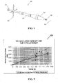
- the shot dispersion angle at the muzzle of the tubes was measured using a high speed camera. Results of this testing are shown in Table 1.
- Table 1 Dispersion Testing Tube Diameter, mm Velocity, m/s (ft/s) Depth, cm (in).
- Pusher Plate Dispersion Angle 40 18.3 (60) 7.6 (3) No 38° 40 24.4 (80) 15.2 (6) No 37° 40 18.3 (60) 30.5 (12) No 31° 40 22.9 (75) 7.6 (3) Yes 34° 40 30 (95) 15.2 (6) Yes 34° 40 30.5 (100) 30.5 (12) Yes 24° 100 18.3 (60) 5.1 (2) No 45° 100 27.4 (90) 10.2 (4) No 59° 100 16.8 (55) 5.1 (2) Yes 45° 100 19.8 (65) 10.2 (4) Yes 53°
- shot materials evaluated include reactive particles, piezoelectric particles and triboelectric particles, where in one embodiment for example, the shot material is ejected to impart an electric charge to the body of the incoming threat so that its detonator prematurely activates. These particles react on impact with the RPG to defeat it by one of the mechanisms described above. Other materials are also contemplated.
- an RPG ogive 300 can be significantly damaged by impact with the pellets. Both steel and tungsten carbide pellets were found to dent or penetrate the ogive 300, with other materials anticipated to have similar results. Pellets that penetrate the ogive can disrupt the shaped charge and reduce its lethal penetrating ability. Ogive dents and/or penetrations 310 can cause short circuiting of the electric detonation circuit (not shown) thereby causing the shaped charge not to actuate upon impact with the target. An observation during testing was that pellet impacts also have the potential for deflecting a RPG off course.
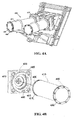
- Figure 4A illustrates a non-limiting embodiment of a pair of warhead shot containers 400 comprised of steel cylindrical tubes 410 mounted at its back ends 415 on bases 420 preferably having, as tested, an inside diameter of approximately 100 mm, a length of approximately 35.6 cm (14 inches), and wall thickness of approximately 0.254 cm (0.1 inches). While two containers are shown, it will be understood that only one container may be utilized, or more than two as the need or situation arises. Furthermore, while the containers are oriented in a consistent relationship, it will be understood that the other orientations are possible as long as there is no detrimental cross-fire.
- a tube 410 is mounted at its back end 415 to a base 420 through the engagement of locking tabs 430 on the tube 410 with locking slots 440 on the base 420.
- a wave spring 450 is further provided on the base for biased contact between the tube 410 and base 420, while a locking pin 460 provides additional secured engagement at the junction of the tube 410 and base 420.
- a contact socket 470 in the base 420 allows for passage of the actuation mechanism that activates the warhead 400.
- FIG. 5 One embodiment of a proven design of a propulsion system at the back end 415 of a warhead 400 is shown in Figure 5 .
- the warheads 400 house pellets 500 and a pusher cup or plate 510.
- the pellets 500 are held in the warhead 400 preferably by a frangible or dislodgeable cover 480 ( Figures 4A, 4B ) secured, for example, by a plastic ring 485.
- Behind the pusher plate 510 is a cylindrical pressure chamber which will propel the pusher plate 510 and pellets 500 when sufficient pressure occurs.
- a high-low adapter 520 and a canister base 515 are welded to the preferably 100 mm canister 505.
- a high pressure 12-gauge insert 525 with a brass burst disk 530 in front of it, is threaded into the high-low adapter 520.
- a pyrotechnic mechanism such as a 12-gauge shotgun shell 540 with a pre-wired primer is inserted into the high pressure insert 525.
- a threaded rod 550 with a large axial hole 552 at the back and a small axial hole 554 at the front, is screwed into the high pressure insert 525 behind the shotgun shell 540.
- Primer wires 560 are threaded through the axial holes 552, 554 and attach to the shot gun shell 540.
- a grooved rubber plug 565 is inserted into the large axial hole 552, with the wires 560 in the groove.
- the wires 560 are threaded through the hole 570 in the threaded cap 575, which is then screwed onto the threaded rod 550.
- the propellant When electronically triggered, the propellant will ignite and will launch the pusher cup 510 and shot 500.
- This propulsion system was employed and performed successfully during live RPG testing. Other propulsion systems are possible, such as sheet explosives, which have the potential for warhead size and weight reduction.
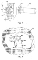
- FIG. 6 Another embodiment of the proven design of a propulsion system useful in the present invention is shown in the warhead tube 600 of Figure 6 .
- a cartridge holder 610 and an O-ring seal 615 are bolted, with lock washers, on the inside of the warhead tube 600.
- a pusher plate 620 and pellets (not shown) are then placed in the tube 600 and held there by a frangible cap 625, secured to the tube 600 by a steel washer 630 and cap screws 635.
- a 20 mm cartridge 640 with an electric primer 645 and containing propellant (not shown) is inserted into the cartridge holder 610 at the back of the warhead and a metal contact bar 650, rubber washers 655, a plastic insulating sleeve 660, an O-ring 670 and a support plate 675 are attached.
- the metal contact bar 655 contacts the center of the primer in the cartridge 640. Rubber and plastic components insulate the contact bar 650 from the rest of the assembled warhead tube 600.
- Another embodiment of a propulsion system useful in the present invention involves using a pneumatic assembly at the back of the warhead tube 600 comprising a pressurized cartridge and a fast acting release valve, wherein such propulsion system utilizes compressed air to propel the pellets.
- two warheads 700 are then inserted into breech blocks 710 with electrical contacts as shown in Figure 7 .
- the metal contact bar 720 on the warhead 700 contacts the positive electronic firing pin 725 in the breech block 710.
- the metal support ring 730 on the warhead 700 contacts the negative firing pin 735.
- each warhead is filled with pellets made of tungsten carbide having a diameter of approximately 0.546 cm (0.215 inches), a density of approximately 14.9 g/cm 3 , and a Rockwell C hardness of approximately 75.
- This configuration results in approximately 15,000 pellets housed in each warhead.
- Other shot configurations are contemplated.
- the pellets are ejected from the two warheads in a non-directed manner and typically radiate as clouds with expanding circular cross-sections that progressively overlap.
- the pellets leave the warheads at speeds between 15.24 m/s and 45.72 m/s (50 ft/s and 150 ft/s) that are non-lethal to nearby personnel.
- the pellets will have a dispersion angle of approximately 40 degrees radiating from each warhead tube, and an overall dispersion angle from a pair of warhead tubes of approximately 60 degrees.
- This configuration using a large number of pellets will result in a high probability of encountering the piezoelectric device on the nose of the missile, and thereby causing premature detonation of the missile. This was confirmed by testing one described typical embodiment system against several separate live RPGs fired from an RPG launcher. The RPGs that entered the protected area of the screen all detonated upon impact with the pellets.
- a series of warheads 800 can be mounted on a vehicle 810 and can protect the vehicle 810 from missile attack. Any structure can be provided with complete coverage by proper placement and orientation of a series of warhead tubes.
- the shot screen 820 is fired in order to strike the missile 3 to 6 m (10 to 20 feet) from the target vehicle or building.
- the speed and approximate trajectory of the missile must also be determined by measurement, typically supported by rapid calculation. Calculations are made to determine if, when and approximately where the missile will strike the vehicle or building, therefore determining which warhead tubes must be fired, and when they need to be fired.
- warhead tubes are mounted statically and are not slewed. The result is an automatic system capable of defeating multiple missiles and thereby protecting vehicles, buildings, and people.
- the shot is fired at non-lethal velocities, since the missile velocity will provide nearly all of the required impact energy.
- the present system preferably contains no high explosives or fuzes, which will lead to ease of transportability and implementation. Also, the system is not lethal to people standing in the path of the shot when fired.
- the shot cloud system is relatively lightweight and easy to deploy. The result of the system is that the incoming missile will detonate prematurely before hitting its target and greatly reduce the resulting damage and loss of life.
Landscapes
- Engineering & Computer Science (AREA)
- General Engineering & Computer Science (AREA)
- Aviation & Aerospace Engineering (AREA)
- Radar, Positioning & Navigation (AREA)
- Remote Sensing (AREA)
- Radar Systems Or Details Thereof (AREA)
- Aiming, Guidance, Guns With A Light Source, Armor, Camouflage, And Targets (AREA)
Claims (13)
- System zum Schutz eines Ziels vor einer anfliegenden Bedrohung (100), wobei die anfliegende Bedrohung (100) eine raketengetriebene Granate (RPG) ist, wobei das System Folgendes umfasst:a. einen Sensor (830) zur Erfassung von Informationen hinsichtlich einer anfliegenden Bedrohung (100);b. wenigstens einen Behälter (400), der ferner mehrere Geschosse (500) umfasst; undc. ein Antriebssystem, das die mehreren Geschosse (500) auf Basis von Informationen, die von dem Sensor (830) erhalten werden, aus dem wenigstens einen Behälter (400) ausstößt;d. wobei die mehreren Geschosse (500) ausgestoßen werden, um die anfliegende Bedrohung (100) abzufangen, um die anfliegende Bedrohung (100) vordem Einschlag an dem Ziel auszuschalten; unde. dadurch gekennzeichnet, dass die mehreren Geschosse (500) mit einer Geschwindigkeit zwischen 15,24 m/s (50 Fuß/s) und 45,72 m/s (150 Fuß/s) ausgestoßen werden, so dass die sich ergebende Geschoßwolke für in der Nähe befindliches Personal nicht tödlich ist.
- System nach Anspruch 1, wobei die mehreren Geschosse (500) auf eine nicht geschwenkte Weise ausgestoßen werden, um eine Geschosswolke zu bilden, die verteilt ist, um die Wahrscheinlichkeit eines Zusammenpralls mit der anfliegenden Bedrohung (100) zu erhöhen.
- System nach Anspruch 1, wobei dir mehreren Geschosse (500) ausgestoßen werden, um die anfliegende Bedrohung (100) vorzeitig zur Explosion zu bringen.
- System nach Anspruch 1, wobei die mehrere Geschosse (500) ausgestoßen werden, um die anfliegende Bedrohung (100) zu treffen und zu beschädigen und die anfliegende Bedrohung (100) dadurch kurzzuschließen, so dass sie beim Einschlag an einem Ziel nicht ausgelöst wird.
- System nach Anspruch 1, wobei die mehreren Geschosse (500) ausgestoßen werden, um die Richtung der anfliegenden Bedrohung (100) umzulenken, so dass sie nicht länger eine Bedrohung für das Ziel darstellt.
- System nach Anspruch 1, wobei die mehreren Geschosse (500) ausgestoßen werden, um dem Körper der anfliegenden Bedrohung (100) eine elektrische Ladung zu verleihen, so dass sich der Zünder vorzeitig aktiviert.
- System nach Anspruch 2, ferner umfassend mehrere Behälter (400), die an dem Ziel angebracht sind, um mehrere Wolken von ausgestoßenen Geschossen (500) zu erzeugen.
- System nach Anspruch 1, wobei die Geschosse (500) ferner ein oder mehr Pellets (150) umfassen, die aus einem Bereich von Materialien gebildet sind, der Stahl, Wolframcarbid, Wolframlegierungen, reaktive Teilchen, piezoelektrische Teilchen oder triboelektrische Teilchen umfasst.
- System nach Anspruch 1, wobei das Antriebssystem zündschnurlos ist.
- System nach Anspruch 9, wobei das Antriebssystem ferner eine Schrotpatrone (540) und eine Schieberplatte (510, 620) zum Ausstoßen der Geschosse (500) aus dem Behälter (400) umfasst.
- System nach Anspruch 1, wobei der Behälter (400) ferner eine zerbrechliche oder entfernbare Abdeckung (480) umfasst, die die Geschosse (500) vor dem Ausstoß in dem Behälter (400) hält.
- System nach Anspruch 1, wobei ein Geschoss (500) der mehreren Geschosse einen Durchmesser von mehr als 0,396 cm (0,156 Zoll) aufweist.
- System nach Anspruch 12, wobei die mehreren Geschosse (500) ferner eines aus Stahl, Wolframcarbid, Wolframlegierungen, reaktiven Teilchen, piezoelektrischen Teilchen oder triboelektrischen Teilchen umfassen.
Applications Claiming Priority (2)
| Application Number | Priority Date | Filing Date | Title |
|---|---|---|---|
| US90880607P | 2007-03-29 | 2007-03-29 | |
| PCT/US2008/058653 WO2008147592A2 (en) | 2007-03-29 | 2008-03-28 | System for protection against missiles |
Publications (3)
| Publication Number | Publication Date |
|---|---|
| EP2205929A2 EP2205929A2 (de) | 2010-07-14 |
| EP2205929A4 EP2205929A4 (de) | 2013-03-27 |
| EP2205929B1 true EP2205929B1 (de) | 2015-10-07 |
Family
ID=40075719
Family Applications (1)
| Application Number | Title | Priority Date | Filing Date |
|---|---|---|---|
| EP08825865.2A Not-in-force EP2205929B1 (de) | 2007-03-29 | 2008-03-28 | System zum schutz vor raketen |
Country Status (3)
| Country | Link |
|---|---|
| US (1) | US20090173250A1 (de) |
| EP (1) | EP2205929B1 (de) |
| WO (1) | WO2008147592A2 (de) |
Families Citing this family (24)
| Publication number | Priority date | Publication date | Assignee | Title |
|---|---|---|---|---|
| US20090217811A1 (en) * | 2006-01-17 | 2009-09-03 | David William Leeming | Textile armour |
| US7900548B2 (en) * | 2006-02-09 | 2011-03-08 | Foster Miller, Inc. | Protection system including a net |
| US7866250B2 (en) * | 2006-02-09 | 2011-01-11 | Foster-Miller, Inc. | Vehicle protection system |
| NL2000406C2 (nl) * | 2006-12-22 | 2008-06-24 | Tno | Werkwijze en inrichting voor het beschermen van objecten tegen raket-aangedreven granaten (RPG's). |
| US8701538B2 (en) | 2007-03-29 | 2014-04-22 | Mechanical Solutions, Inc. | System for protection against missiles |
| US8464627B2 (en) | 2008-04-16 | 2013-06-18 | QinetiQ North America, Inc. | Vehicle and structure shield with improved hard points |
| US8245620B2 (en) * | 2008-04-16 | 2012-08-21 | QinetiQ North America, Inc. | Low breaking strength vehicle and structure shield net/frame arrangement |
| US8453552B2 (en) | 2008-04-16 | 2013-06-04 | QinetiQ North America, Inc. | Method of designing an RPG shield |
| US20110079135A1 (en) | 2008-04-16 | 2011-04-07 | Farinella Michael D | Vehicle and structure shield net/frame arrangement |
| US8468927B2 (en) | 2008-04-16 | 2013-06-25 | QinetiQ North America, Inc. | Vehicle and structure shield with a cable frame |
| US8011285B2 (en) | 2008-04-16 | 2011-09-06 | Foster-Miller, Inc. | Vehicle and structure shield |
| US8607685B2 (en) | 2008-04-16 | 2013-12-17 | QinetiQ North America, Inc. | Load sharing hard point net |
| US8615851B2 (en) | 2008-04-16 | 2013-12-31 | Foster-Miller, Inc. | Net patching devices |
| US8443709B2 (en) * | 2008-04-16 | 2013-05-21 | QinetiQ North America, Inc. | Vehicle and structure shield hard point |
| US8677882B2 (en) | 2010-09-08 | 2014-03-25 | QinetiQ North America, Inc. | Vehicle and structure shield with flexible frame |
| US8448560B1 (en) | 2011-05-11 | 2013-05-28 | The United States Of America As Represented By The Secretary Of The Army | Propelled impacter reactive armor |
| US8813631B1 (en) | 2013-02-13 | 2014-08-26 | Foster-Miller, Inc. | Vehicle and structure film/hard point shield |
| PL225266B1 (pl) | 2014-05-07 | 2017-03-31 | Wojskowa Akad Tech | System obrony aktywnej |
| US20170356726A1 (en) * | 2015-02-26 | 2017-12-14 | Shawn M. Theiss | Aerial arresting system for unmanned aerial vehicle |
| DE102015011058A1 (de) * | 2015-08-27 | 2017-03-02 | Rheinmetall Waffe Munition Gmbh | System zur Abwehr von Bedrohungen |
| US10005556B2 (en) | 2015-11-25 | 2018-06-26 | Mohammad Rastgaar Aagaah | Drone having drone-catching feature |
| US11027845B2 (en) | 2017-09-29 | 2021-06-08 | Shawn M. Theiss | Device and method to intercept an aerial vehicle |
| IL284594A (en) | 2021-07-04 | 2023-02-01 | Cohen David | an interceptor |
| CN113959266A (zh) * | 2021-11-18 | 2022-01-21 | 内蒙古第一机械集团股份有限公司 | 一种主动防护式爆炸反应装甲组件 |
Family Cites Families (13)
| Publication number | Priority date | Publication date | Assignee | Title |
|---|---|---|---|---|
| US455971A (en) * | 1891-07-14 | mcg-ahan | ||
| DE3127674A1 (de) * | 1981-07-14 | 1983-02-24 | Rheinmetall GmbH, 4000 Düsseldorf | Verfahren und vorrichtung zum belegen einer zielflaeche mit munition |
| DE69321142T2 (de) * | 1993-12-01 | 1999-02-25 | Konstruktorskoe Bjuro Masinostroenja, Kolomna | Fahrzeug-selbstverteidigungssystem |
| US5898125A (en) * | 1995-10-17 | 1999-04-27 | Foster-Miller, Inc. | Ballistically deployed restraining net |
| US6279482B1 (en) * | 1996-07-25 | 2001-08-28 | Trw Inc. | Countermeasure apparatus for deploying interceptor elements from a spin stabilized rocket |
| AUPR629401A0 (en) * | 2001-07-11 | 2001-08-02 | Metal Storm Limited | Projectiles |
| US7100514B2 (en) * | 2003-08-13 | 2006-09-05 | Harrington Group Ltd. | Piezoelectric incapacitation projectile |
| US7190304B1 (en) * | 2003-12-12 | 2007-03-13 | Bae Systems Information And Electronic Systems Integration Inc. | System for interception and defeat of rocket propelled grenades and method of use |
| US7066427B2 (en) * | 2004-02-26 | 2006-06-27 | Chang Industry, Inc. | Active protection device and associated apparatus, system, and method |
| US6957602B1 (en) * | 2004-04-28 | 2005-10-25 | The United States Of America As Represented By The Secretary Of The Army | Parachute active protection apparatus |
| US7202809B1 (en) * | 2004-05-10 | 2007-04-10 | Bae Systems Land & Armaments L.P. | Fast acting active protection system |
| DE102005038071A1 (de) * | 2005-08-10 | 2007-02-15 | Rheinmetall Waffe Munition Gmbh | Vorrichtung sowie Verfahren zum Schutz von Fahrzeugen vor Munition, insbesondere vor Hohlladungsgeschossen |
| US7944674B2 (en) * | 2006-03-24 | 2011-05-17 | Applied Energetics, Inc. | Barrier piercing electrode |
-
2008
- 2008-03-28 US US12/058,003 patent/US20090173250A1/en not_active Abandoned
- 2008-03-28 WO PCT/US2008/058653 patent/WO2008147592A2/en not_active Ceased
- 2008-03-28 EP EP08825865.2A patent/EP2205929B1/de not_active Not-in-force
Also Published As
| Publication number | Publication date |
|---|---|
| US20090173250A1 (en) | 2009-07-09 |
| WO2008147592A2 (en) | 2008-12-04 |
| EP2205929A4 (de) | 2013-03-27 |
| EP2205929A2 (de) | 2010-07-14 |
| WO2008147592A3 (en) | 2011-07-28 |
Similar Documents
| Publication | Publication Date | Title |
|---|---|---|
| EP2205929B1 (de) | System zum schutz vor raketen | |
| US9366508B2 (en) | System for protection against missiles | |
| RU2293281C2 (ru) | Снаряд для метания и способы его использования | |
| US8468946B2 (en) | Low shrapnel door breaching projectile system | |
| US20020088367A1 (en) | Non-lethal ballistic | |
| US8528480B2 (en) | Warhead | |
| US9982978B2 (en) | Warhead for generating a blast on an extended region of a target surface | |
| EP0735342B1 (de) | Munitionseinheit zum selbstschutz für einen panzer | |
| US8316772B1 (en) | Wall breaching fragmentation warhead | |
| PL225266B1 (pl) | System obrony aktywnej | |
| US7387060B1 (en) | Rocket exhaust defense system and method | |
| US8196513B1 (en) | Stand-off disrupter apparatus | |
| RU2515939C1 (ru) | Кассетный боеприпас "городня" | |
| WO2016114743A1 (ru) | Способ гиперзвуковой защиты танка | |
| US20200278181A1 (en) | Reactive armor | |
| CN117387432A (zh) | 基于多efp技术的杀伤弹 | |
| JP7128205B2 (ja) | 選択可能な迎え角を有する発射物 | |
| RU2851639C1 (ru) | Боеприпасы ДГУ бронеобъекта (варианты) | |
| KR102601642B1 (ko) | 발사체 | |
| RU2339898C2 (ru) | Система самообороны транспортного средства "инрог" | |
| RU2263268C2 (ru) | Система вооружения комплекса активной защиты | |
| RU2363913C1 (ru) | Осколочно-пучковый кумулятивный снаряд "весьегонск" | |
| Held | Threats to military transport aircraft: A technical review | |
| WO2010064253A1 (en) | Self defense projectile |
Legal Events
| Date | Code | Title | Description |
|---|---|---|---|
| PUAI | Public reference made under article 153(3) epc to a published international application that has entered the european phase |
Free format text: ORIGINAL CODE: 0009012 |
|
| 17P | Request for examination filed |
Effective date: 20091020 |
|
| AK | Designated contracting states |
Kind code of ref document: A2 Designated state(s): AT BE BG CH CY CZ DE DK EE ES FI FR GB GR HR HU IE IS IT LI LT LU LV MC MT NL NO PL PT RO SE SI SK TR |
|
| DAX | Request for extension of the european patent (deleted) | ||
| A4 | Supplementary search report drawn up and despatched |
Effective date: 20130226 |
|
| RIC1 | Information provided on ipc code assigned before grant |
Ipc: F42B 12/56 20060101ALI20130220BHEP Ipc: F41H 11/02 20060101AFI20130220BHEP Ipc: F41H 5/007 20060101ALI20130220BHEP |
|
| 17Q | First examination report despatched |
Effective date: 20140428 |
|
| REG | Reference to a national code |
Ref country code: DE Ref legal event code: R079 Ref document number: 602008040566 Country of ref document: DE Free format text: PREVIOUS MAIN CLASS: F41H0011020000 Ipc: F41H0005007000 |
|
| GRAP | Despatch of communication of intention to grant a patent |
Free format text: ORIGINAL CODE: EPIDOSNIGR1 |
|
| RIC1 | Information provided on ipc code assigned before grant |
Ipc: F42B 23/04 20060101ALN20150305BHEP Ipc: F41H 5/007 20060101AFI20150305BHEP Ipc: F41H 11/02 20060101ALI20150305BHEP Ipc: F42B 5/145 20060101ALI20150305BHEP Ipc: F42B 12/56 20060101ALN20150305BHEP Ipc: F42B 23/24 20060101ALN20150305BHEP |
|
| INTG | Intention to grant announced |
Effective date: 20150326 |
|
| GRAS | Grant fee paid |
Free format text: ORIGINAL CODE: EPIDOSNIGR3 |
|
| GRAA | (expected) grant |
Free format text: ORIGINAL CODE: 0009210 |
|
| AK | Designated contracting states |
Kind code of ref document: B1 Designated state(s): AT BE BG CH CY CZ DE DK EE ES FI FR GB GR HR HU IE IS IT LI LT LU LV MC MT NL NO PL PT RO SE SI SK TR |
|
| REG | Reference to a national code |
Ref country code: GB Ref legal event code: FG4D |
|
| REG | Reference to a national code |
Ref country code: AT Ref legal event code: REF Ref document number: 754004 Country of ref document: AT Kind code of ref document: T Effective date: 20151015 Ref country code: CH Ref legal event code: EP |
|
| REG | Reference to a national code |
Ref country code: IE Ref legal event code: FG4D |
|
| REG | Reference to a national code |
Ref country code: DE Ref legal event code: R096 Ref document number: 602008040566 Country of ref document: DE |
|
| REG | Reference to a national code |
Ref country code: SE Ref legal event code: TRGR |
|
| REG | Reference to a national code |
Ref country code: NL Ref legal event code: MP Effective date: 20151007 |
|
| REG | Reference to a national code |
Ref country code: AT Ref legal event code: MK05 Ref document number: 754004 Country of ref document: AT Kind code of ref document: T Effective date: 20151007 |
|
| REG | Reference to a national code |
Ref country code: LT Ref legal event code: MG4D |
|
| REG | Reference to a national code |
Ref country code: FR Ref legal event code: PLFP Year of fee payment: 9 Ref country code: FR Ref legal event code: PLFP Year of fee payment: 10 |
|
| PG25 | Lapsed in a contracting state [announced via postgrant information from national office to epo] |
Ref country code: ES Free format text: LAPSE BECAUSE OF FAILURE TO SUBMIT A TRANSLATION OF THE DESCRIPTION OR TO PAY THE FEE WITHIN THE PRESCRIBED TIME-LIMIT Effective date: 20151007 Ref country code: NL Free format text: LAPSE BECAUSE OF FAILURE TO SUBMIT A TRANSLATION OF THE DESCRIPTION OR TO PAY THE FEE WITHIN THE PRESCRIBED TIME-LIMIT Effective date: 20151007 Ref country code: HR Free format text: LAPSE BECAUSE OF FAILURE TO SUBMIT A TRANSLATION OF THE DESCRIPTION OR TO PAY THE FEE WITHIN THE PRESCRIBED TIME-LIMIT Effective date: 20151007 Ref country code: LT Free format text: LAPSE BECAUSE OF FAILURE TO SUBMIT A TRANSLATION OF THE DESCRIPTION OR TO PAY THE FEE WITHIN THE PRESCRIBED TIME-LIMIT Effective date: 20151007 Ref country code: IT Free format text: LAPSE BECAUSE OF FAILURE TO SUBMIT A TRANSLATION OF THE DESCRIPTION OR TO PAY THE FEE WITHIN THE PRESCRIBED TIME-LIMIT Effective date: 20151007 Ref country code: NO Free format text: LAPSE BECAUSE OF FAILURE TO SUBMIT A TRANSLATION OF THE DESCRIPTION OR TO PAY THE FEE WITHIN THE PRESCRIBED TIME-LIMIT Effective date: 20160107 Ref country code: IS Free format text: LAPSE BECAUSE OF FAILURE TO SUBMIT A TRANSLATION OF THE DESCRIPTION OR TO PAY THE FEE WITHIN THE PRESCRIBED TIME-LIMIT Effective date: 20160207 |
|
| PG25 | Lapsed in a contracting state [announced via postgrant information from national office to epo] |
Ref country code: LV Free format text: LAPSE BECAUSE OF FAILURE TO SUBMIT A TRANSLATION OF THE DESCRIPTION OR TO PAY THE FEE WITHIN THE PRESCRIBED TIME-LIMIT Effective date: 20151007 Ref country code: PL Free format text: LAPSE BECAUSE OF FAILURE TO SUBMIT A TRANSLATION OF THE DESCRIPTION OR TO PAY THE FEE WITHIN THE PRESCRIBED TIME-LIMIT Effective date: 20151007 Ref country code: FI Free format text: LAPSE BECAUSE OF FAILURE TO SUBMIT A TRANSLATION OF THE DESCRIPTION OR TO PAY THE FEE WITHIN THE PRESCRIBED TIME-LIMIT Effective date: 20151007 Ref country code: GR Free format text: LAPSE BECAUSE OF FAILURE TO SUBMIT A TRANSLATION OF THE DESCRIPTION OR TO PAY THE FEE WITHIN THE PRESCRIBED TIME-LIMIT Effective date: 20160108 Ref country code: PT Free format text: LAPSE BECAUSE OF FAILURE TO SUBMIT A TRANSLATION OF THE DESCRIPTION OR TO PAY THE FEE WITHIN THE PRESCRIBED TIME-LIMIT Effective date: 20160208 Ref country code: AT Free format text: LAPSE BECAUSE OF FAILURE TO SUBMIT A TRANSLATION OF THE DESCRIPTION OR TO PAY THE FEE WITHIN THE PRESCRIBED TIME-LIMIT Effective date: 20151007 |
|
| REG | Reference to a national code |
Ref country code: DE Ref legal event code: R097 Ref document number: 602008040566 Country of ref document: DE |
|
| PG25 | Lapsed in a contracting state [announced via postgrant information from national office to epo] |
Ref country code: CZ Free format text: LAPSE BECAUSE OF FAILURE TO SUBMIT A TRANSLATION OF THE DESCRIPTION OR TO PAY THE FEE WITHIN THE PRESCRIBED TIME-LIMIT Effective date: 20151007 |
|
| PLBE | No opposition filed within time limit |
Free format text: ORIGINAL CODE: 0009261 |
|
| STAA | Information on the status of an ep patent application or granted ep patent |
Free format text: STATUS: NO OPPOSITION FILED WITHIN TIME LIMIT |
|
| PG25 | Lapsed in a contracting state [announced via postgrant information from national office to epo] |
Ref country code: EE Free format text: LAPSE BECAUSE OF FAILURE TO SUBMIT A TRANSLATION OF THE DESCRIPTION OR TO PAY THE FEE WITHIN THE PRESCRIBED TIME-LIMIT Effective date: 20151007 Ref country code: DK Free format text: LAPSE BECAUSE OF FAILURE TO SUBMIT A TRANSLATION OF THE DESCRIPTION OR TO PAY THE FEE WITHIN THE PRESCRIBED TIME-LIMIT Effective date: 20151007 Ref country code: BE Free format text: LAPSE BECAUSE OF NON-PAYMENT OF DUE FEES Effective date: 20160331 Ref country code: RO Free format text: LAPSE BECAUSE OF FAILURE TO SUBMIT A TRANSLATION OF THE DESCRIPTION OR TO PAY THE FEE WITHIN THE PRESCRIBED TIME-LIMIT Effective date: 20151007 Ref country code: SK Free format text: LAPSE BECAUSE OF FAILURE TO SUBMIT A TRANSLATION OF THE DESCRIPTION OR TO PAY THE FEE WITHIN THE PRESCRIBED TIME-LIMIT Effective date: 20151007 |
|
| PGFP | Annual fee paid to national office [announced via postgrant information from national office to epo] |
Ref country code: FR Payment date: 20160413 Year of fee payment: 9 |
|
| 26N | No opposition filed |
Effective date: 20160708 |
|
| PG25 | Lapsed in a contracting state [announced via postgrant information from national office to epo] |
Ref country code: LU Free format text: LAPSE BECAUSE OF FAILURE TO SUBMIT A TRANSLATION OF THE DESCRIPTION OR TO PAY THE FEE WITHIN THE PRESCRIBED TIME-LIMIT Effective date: 20160328 Ref country code: MC Free format text: LAPSE BECAUSE OF FAILURE TO SUBMIT A TRANSLATION OF THE DESCRIPTION OR TO PAY THE FEE WITHIN THE PRESCRIBED TIME-LIMIT Effective date: 20151007 |
|
| REG | Reference to a national code |
Ref country code: CH Ref legal event code: PL |
|
| PG25 | Lapsed in a contracting state [announced via postgrant information from national office to epo] |
Ref country code: SI Free format text: LAPSE BECAUSE OF FAILURE TO SUBMIT A TRANSLATION OF THE DESCRIPTION OR TO PAY THE FEE WITHIN THE PRESCRIBED TIME-LIMIT Effective date: 20151007 |
|
| REG | Reference to a national code |
Ref country code: IE Ref legal event code: MM4A |
|
| PG25 | Lapsed in a contracting state [announced via postgrant information from national office to epo] |
Ref country code: BE Free format text: LAPSE BECAUSE OF FAILURE TO SUBMIT A TRANSLATION OF THE DESCRIPTION OR TO PAY THE FEE WITHIN THE PRESCRIBED TIME-LIMIT Effective date: 20151007 |
|
| PG25 | Lapsed in a contracting state [announced via postgrant information from national office to epo] |
Ref country code: LI Free format text: LAPSE BECAUSE OF NON-PAYMENT OF DUE FEES Effective date: 20160331 Ref country code: CH Free format text: LAPSE BECAUSE OF NON-PAYMENT OF DUE FEES Effective date: 20160331 Ref country code: IE Free format text: LAPSE BECAUSE OF NON-PAYMENT OF DUE FEES Effective date: 20160328 |
|
| PGFP | Annual fee paid to national office [announced via postgrant information from national office to epo] |
Ref country code: SE Payment date: 20170215 Year of fee payment: 10 Ref country code: DE Payment date: 20170216 Year of fee payment: 10 |
|
| PGFP | Annual fee paid to national office [announced via postgrant information from national office to epo] |
Ref country code: GB Payment date: 20170222 Year of fee payment: 10 |
|
| PG25 | Lapsed in a contracting state [announced via postgrant information from national office to epo] |
Ref country code: MT Free format text: LAPSE BECAUSE OF FAILURE TO SUBMIT A TRANSLATION OF THE DESCRIPTION OR TO PAY THE FEE WITHIN THE PRESCRIBED TIME-LIMIT Effective date: 20151007 |
|
| PG25 | Lapsed in a contracting state [announced via postgrant information from national office to epo] |
Ref country code: HU Free format text: LAPSE BECAUSE OF FAILURE TO SUBMIT A TRANSLATION OF THE DESCRIPTION OR TO PAY THE FEE WITHIN THE PRESCRIBED TIME-LIMIT; INVALID AB INITIO Effective date: 20080328 Ref country code: CY Free format text: LAPSE BECAUSE OF FAILURE TO SUBMIT A TRANSLATION OF THE DESCRIPTION OR TO PAY THE FEE WITHIN THE PRESCRIBED TIME-LIMIT Effective date: 20151007 |
|
| PG25 | Lapsed in a contracting state [announced via postgrant information from national office to epo] |
Ref country code: MT Free format text: LAPSE BECAUSE OF FAILURE TO SUBMIT A TRANSLATION OF THE DESCRIPTION OR TO PAY THE FEE WITHIN THE PRESCRIBED TIME-LIMIT Effective date: 20160331 Ref country code: TR Free format text: LAPSE BECAUSE OF FAILURE TO SUBMIT A TRANSLATION OF THE DESCRIPTION OR TO PAY THE FEE WITHIN THE PRESCRIBED TIME-LIMIT Effective date: 20151007 |
|
| PG25 | Lapsed in a contracting state [announced via postgrant information from national office to epo] |
Ref country code: BG Free format text: LAPSE BECAUSE OF FAILURE TO SUBMIT A TRANSLATION OF THE DESCRIPTION OR TO PAY THE FEE WITHIN THE PRESCRIBED TIME-LIMIT Effective date: 20151007 |
|
| REG | Reference to a national code |
Ref country code: DE Ref legal event code: R119 Ref document number: 602008040566 Country of ref document: DE |
|
| PG25 | Lapsed in a contracting state [announced via postgrant information from national office to epo] |
Ref country code: SE Free format text: LAPSE BECAUSE OF NON-PAYMENT OF DUE FEES Effective date: 20180329 |
|
| GBPC | Gb: european patent ceased through non-payment of renewal fee |
Effective date: 20180328 |
|
| PG25 | Lapsed in a contracting state [announced via postgrant information from national office to epo] |
Ref country code: DE Free format text: LAPSE BECAUSE OF NON-PAYMENT OF DUE FEES Effective date: 20181002 |
|
| PG25 | Lapsed in a contracting state [announced via postgrant information from national office to epo] |
Ref country code: GB Free format text: LAPSE BECAUSE OF NON-PAYMENT OF DUE FEES Effective date: 20180328 |
|
| PG25 | Lapsed in a contracting state [announced via postgrant information from national office to epo] |
Ref country code: FR Free format text: LAPSE BECAUSE OF NON-PAYMENT OF DUE FEES Effective date: 20170331 |