EP2206073B1 - Procédé pour différencier des réflecteurs de bords de voies de circulation et des feux de position de véhicule, dans l'obscurité - Google Patents
Procédé pour différencier des réflecteurs de bords de voies de circulation et des feux de position de véhicule, dans l'obscurité Download PDFInfo
- Publication number
- EP2206073B1 EP2206073B1 EP08841153.3A EP08841153A EP2206073B1 EP 2206073 B1 EP2206073 B1 EP 2206073B1 EP 08841153 A EP08841153 A EP 08841153A EP 2206073 B1 EP2206073 B1 EP 2206073B1
- Authority
- EP
- European Patent Office
- Prior art keywords
- light
- reflectors
- vehicle
- found
- map
- Prior art date
- Legal status (The legal status is an assumption and is not a legal conclusion. Google has not performed a legal analysis and makes no representation as to the accuracy of the status listed.)
- Active
Links
Images
Classifications
-
- B—PERFORMING OPERATIONS; TRANSPORTING
- B60—VEHICLES IN GENERAL
- B60Q—ARRANGEMENT OF SIGNALLING OR LIGHTING DEVICES, THE MOUNTING OR SUPPORTING THEREOF OR CIRCUITS THEREFOR, FOR VEHICLES IN GENERAL
- B60Q1/00—Arrangement of optical signalling or lighting devices, the mounting or supporting thereof or circuits therefor
- B60Q1/02—Arrangement of optical signalling or lighting devices, the mounting or supporting thereof or circuits therefor the devices being primarily intended to illuminate the way ahead or to illuminate other areas of way or environments
- B60Q1/04—Arrangement of optical signalling or lighting devices, the mounting or supporting thereof or circuits therefor the devices being primarily intended to illuminate the way ahead or to illuminate other areas of way or environments the devices being headlights
- B60Q1/14—Arrangement of optical signalling or lighting devices, the mounting or supporting thereof or circuits therefor the devices being primarily intended to illuminate the way ahead or to illuminate other areas of way or environments the devices being headlights having dimming means
- B60Q1/1415—Dimming circuits
- B60Q1/1423—Automatic dimming circuits, i.e. switching between high beam and low beam due to change of ambient light or light level in road traffic
- B60Q1/143—Automatic dimming circuits, i.e. switching between high beam and low beam due to change of ambient light or light level in road traffic combined with another condition, e.g. using vehicle recognition from camera images or activation of wipers
-
- G—PHYSICS
- G06—COMPUTING OR CALCULATING; COUNTING
- G06V—IMAGE OR VIDEO RECOGNITION OR UNDERSTANDING
- G06V20/00—Scenes; Scene-specific elements
- G06V20/50—Context or environment of the image
- G06V20/56—Context or environment of the image exterior to a vehicle by using sensors mounted on the vehicle
- G06V20/58—Recognition of moving objects or obstacles, e.g. vehicles or pedestrians; Recognition of traffic objects, e.g. traffic signs, traffic lights or roads
- G06V20/584—Recognition of moving objects or obstacles, e.g. vehicles or pedestrians; Recognition of traffic objects, e.g. traffic signs, traffic lights or roads of vehicle lights or traffic lights
-
- B—PERFORMING OPERATIONS; TRANSPORTING
- B60—VEHICLES IN GENERAL
- B60Q—ARRANGEMENT OF SIGNALLING OR LIGHTING DEVICES, THE MOUNTING OR SUPPORTING THEREOF OR CIRCUITS THEREFOR, FOR VEHICLES IN GENERAL
- B60Q2300/00—Indexing codes for automatically adjustable headlamps or automatically dimmable headlamps
- B60Q2300/30—Indexing codes relating to the vehicle environment
- B60Q2300/32—Road surface or travel path
- B60Q2300/322—Road curvature
-
- B—PERFORMING OPERATIONS; TRANSPORTING
- B60—VEHICLES IN GENERAL
- B60Q—ARRANGEMENT OF SIGNALLING OR LIGHTING DEVICES, THE MOUNTING OR SUPPORTING THEREOF OR CIRCUITS THEREFOR, FOR VEHICLES IN GENERAL
- B60Q2300/00—Indexing codes for automatically adjustable headlamps or automatically dimmable headlamps
- B60Q2300/40—Indexing codes relating to other road users or special conditions
- B60Q2300/41—Indexing codes relating to other road users or special conditions preceding vehicle
-
- B—PERFORMING OPERATIONS; TRANSPORTING
- B60—VEHICLES IN GENERAL
- B60Q—ARRANGEMENT OF SIGNALLING OR LIGHTING DEVICES, THE MOUNTING OR SUPPORTING THEREOF OR CIRCUITS THEREFOR, FOR VEHICLES IN GENERAL
- B60Q2300/00—Indexing codes for automatically adjustable headlamps or automatically dimmable headlamps
- B60Q2300/40—Indexing codes relating to other road users or special conditions
- B60Q2300/42—Indexing codes relating to other road users or special conditions oncoming vehicle
-
- B—PERFORMING OPERATIONS; TRANSPORTING
- B60—VEHICLES IN GENERAL
- B60Q—ARRANGEMENT OF SIGNALLING OR LIGHTING DEVICES, THE MOUNTING OR SUPPORTING THEREOF OR CIRCUITS THEREFOR, FOR VEHICLES IN GENERAL
- B60Q2300/00—Indexing codes for automatically adjustable headlamps or automatically dimmable headlamps
- B60Q2300/40—Indexing codes relating to other road users or special conditions
- B60Q2300/45—Special conditions, e.g. pedestrians, road signs or potential dangers
Definitions
- the invention relates to a method for distinguishing reflectors on the roadside and vehicle lights according to the preamble of claim 1 for use in motor vehicles.
- the document WO 2004/034183 A2 discloses a method for automatic light control for a motor vehicle with a camera environment-oriented camera sensor, which provides at least one category for self-beaming moving lights, in particular vehicle lights, wherein a sequence of images of the vehicle environment is recorded, at least one light spot in the image sequence tracked (tracked) and the Intensity of a tracked light spot is determined in at least two images, the measured intensity is analyzed, from the intensity values the lights of other vehicles are detected, and headlights are controlled so that drivers of other vehicles are not dazzled. An analysis of the movement of a point of light is also the basis for the categorization.
- the EP 1 837 803 A2 shows a method according to the preamble of claim 1.
- statistical information on shape, motion, brightness, spatial extent, and color is collected. Based on this statistical information, the light points are classified by a pre-trained classifier.
- the US 2006/0106518 A1 shows improvements for vehicle camera systems and a camera-based lighting control.
- Light points are determined as brightness maxima in the camera image. Different properties of light points such as brightness, color, position, width, height and movement are determined. The values of these parameters are analyzed by statistical methods to determine if the light spots correspond to headlights or taillights of other vehicles or other non-vehicle light sources such as signs, reflectors or other stationary lights.
- the object of the present invention is a method which offers increased reliability of the distinction between reflectors and vehicle lights.
- the basic idea of the invention is to exploit the fact that reflectors are arranged on the roadside edge and the lights of oncoming or preceding vehicles are in most cases on the roadway. As a result, regions in which it is more likely to find reflectors and regions in which it is more likely to find vehicle lights can be determined on the camera image. This knowledge is used to distinguish and identify points of light.
- An inventive method for distinguishing and identifying reflectors at the edge of the road and vehicle lights for use in an automatic light control in a vehicle comprises a camera sensor aligned in the vehicle surroundings.
- the camera sensor records a sequence of images of the vehicle environment. Points of light are found within the image sequence and tracked in time (tracked). For each light point is subsequently decided whether the light spot has a vehicle light or a reflector on the roadside as a light source.
- the subsequent identification of a light spot can be done in particular on the basis of its maximum intensity and / or its lifetime.
- a statistical map for the entire camera image is determined.
- the statistical map results from the type and positions of the already found and identified points of light.
- the statistical map includes areas or sectors that are predominantly occupied by reflectors and areas or sectors that are predominantly occupied by vehicles in front or on the opposite side.
- a potential reflector means that such a light spot is more likely to be identified as a reflector than a light spot that was not found within a region covered with reflectors. If there is no other distinguishing criterion or should be considered, a spot of light found within a reflector-occupied area would be identified as a reflector. All light sources that lie within the areas occupied by vehicle lights are identified accordingly as potential vehicle lights.
- light spots which are arranged in the image on a line with further light spots are identified as potential reflectors.
- light points whose spatial arrangement of a periodic arrangement of Corresponds to light sources in real space identified as potential reflectors.
- a statistical map is created in world coordinates.
- the World Map statistical map includes areas that are primarily occupied by reflectors and areas that are primarily occupied by vehicles in front or oncoming traffic.
- the decision as to whether the light spot has a vehicle light or a reflector as a light source can be made taking into consideration the direction and the length of a displacement vector for the tracked light spot.
- the displacement vector indicates by what amount (length) and in which direction a light spot has moved from an image to the subsequent image.
- the speed of the own vehicle can be taken into account. If the displacement vectors are scaled accordingly, a velocity-invariant distribution of the displacement vectors results.
- Reflectors can be recognized by the fact that the displacement vectors of the corresponding points of light essentially correspond to the movement of the vehicle. In the velocity-invariant representation, displacement vectors of reflectors are theoretically zero.
- the time of the decision as to whether the light source is a vehicle or a reflector depends on the position at which the light spot is found, and delayed or accelerated by the intensity of the light spot.
- the influence of the statistical map and the influence of other criteria such as the current intensity of a light spot, the linear and / or periodic arrangement of light points on the distinction and identification can be weighted differently. For example, if there is only one clue that speaks for a vehicle light, a quick decision should be made so that the automatic light control dimmers so as not to dazzle other drivers. If, on the other hand, there are predominantly indications that speak for a reflector, the decision can be delayed until the decision-making basis is more reliable.
- the map consisting of continuous or discrete areas may be provided with a forgetting factor to take account of changes in the course of the road and / or the surrounding area.
- the steering angle and / or yaw angle is known, for example, from sensor data, and the map is adapted in its curvature to the course of the road.
- a sensor-based track finding is provided, are supplied by the information about the lane ahead.
- the track finding may be based, for example, on data from a radar, lidar or a Kämerasensors. Based on this information on the road ahead, the location of the areas where potential reflectors are located is adjusted on the statistical map.
- the lane course can also be determined using a GPS receiver and a digital road map, which are present for example in a navigation device.
- the information from the navigation device can also be combined with those of the sensor-based tracking.
- the statistical map can also be adapted to the width of the roadway determined by the track finding or to the determined current driving behavior.
- the current driving behavior here includes a lane change or changes in the yaw angle.
- the invention also includes an apparatus for distinguishing and identifying roadside reflectors and vehicle lights in a vehicle environment.
- the device comprises a camera sensor and an evaluation unit, which evaluates the image data captured by the camera sensor by one of the aforementioned methods.
- the advantage of the invention lies in the increase of the discrimination security between reflectors and vehicle lights. This prevents malfunctions of the automatic light control, driving comfort and safety are increased. The time until a distinction can be made is reduced by the use of a statistical map.
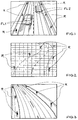
- Fig. 1 is schematically shown a captured by the camera sensor image.
- the picture shows a carriageway, an oncoming and a preceding vehicle (FL1, FL2) and reflectors (R), which are arranged at the roadside. In the dark, the vehicles and street boundary posts are visible only as points of light.
- the picture is divided into sectors. In the example of Fig. 1 the sectors are defined by equally wide (eg 1 m wide) strips running in the direction of travel. This sector division is particularly suitable for straight road sections.
- the camera sensor takes a sequence of pictures. Points of light are found within the image sequence and tracked (timed). It is subsequently decided for each light spot whether the light spot has a vehicle light (FL1, FL2) or a reflector (R) on the edge of the road as the light source. This distinction can be made on intensity traces, motion patterns or other suitable parameters.
- a frequency distribution is established in which sector how frequently a reflector (R) or a vehicle light (FL1, FL2) was identified. From this frequency distribution results the statistical map for the entire camera image, which results from the sectors. Of the For each sector, the statistical map shows how often reflectors (R) have been identified or how often lights from preceding (FL2) or oncoming (FL1) vehicles have been identified.
- a statistical map for the situation Fig. 1 would result in neutral sectors (far left, far right), sectors with high reflector occurrences (R) (left and right margins) and sectors with high vehicle light (FL1, FL2) (sectors on the pavement).
- the camera sensor records an image with a new light spot and the light spot is found by an evaluation unit, it is determined from the statistical map how often in the sector in which the light spot was found, reflectors (R) or vehicle lights (FL1, FL2 ) appeared. If more reflectors (R) than vehicle lights (FL1, FL2) have occurred in the sector, the light spot is identified as a potential reflector (R) and vice versa.
- Reflectors (R) are like in Fig. 1 frequently arranged on a line with further reflectors (R).
- the spatial arrangement of reflectors (R) corresponds frequently a periodic arrangement of reflectors (R) with uniform distances between two reflectors (R) in real space.
- displacement vectors of light spots are facilitated by knowing the speed of the own vehicle. In this case, it is known which pixel of a stationary environment shifts as much. Thus, a determined displacement vector can be transformed into the system of the moving vehicle.
- the displacement vectors thus transformed are also referred to as velocity-invariant.
- the velocity-invariant displacement vectors there are those pointing in the direction of travel, those facing the (own) direction of travel and those representing no movement. These correspond to preceding vehicles (FL2), oncoming vehicles (FL1) and stationary reflectors (R).
- Fig. 2 the camera image is subdivided in the form of a grid.
- the sectors are rectangular.
- the compared to Fig. 1 A finer division into a larger number of sectors offers the advantage that a corresponding statistical map can take account of winding roads.
- the statistical map is generated in the manner already described and corresponds to a collection of trajectories of identified points of light with the resolution of the grid.
- Fig. 3 is shown as an example how the sectors are adapted to the road course.
- the road course is determined by a radar, Lidar- or camera-based track finding.
- the position of the sectors in which potential reflectors (R) or vehicle lights (FL1, FL2) are located is adapted on the statistical map.
- the representation in Fig. 3 shows a left turn. Accordingly, the sectors, which in turn correspond to parallel strips of predetermined width, are curved by the same radius of curvature. All left reflectors (R) and all right reflectors (R) are each in one sector. For a different sector width, there could also be two or three sectors in each case in which reflectors (R) are located. By contrast, in the sectors between the sectors covered with reflectors (R), vehicle lights (FL1, FL2) will be found more frequently.
Landscapes
- Engineering & Computer Science (AREA)
- Mechanical Engineering (AREA)
- Physics & Mathematics (AREA)
- General Physics & Mathematics (AREA)
- Multimedia (AREA)
- Theoretical Computer Science (AREA)
- Traffic Control Systems (AREA)
- Lighting Device Outwards From Vehicle And Optical Signal (AREA)
Claims (8)
- Procédé pour distinguer et identifier des réflecteurs (R) sur le bord de voies de circulation et des feux de position (FL1, FL2), destiné à être utilisé dans un véhicule avec un capteur de caméra orienté vers l'environnement du véhicule,- une suite d'images de l'environnement du véhicule étant prise,- des points lumineux étant trouvés à l'intérieur de la suite d'images et suivis dans le temps (poursuivis),caractérisé en ce que,- postérieurement au suivi dans le temps de points lumineux trouvés à l'intérieur de la suite d'images, il est décidé, pour chaque point lumineux, si le point lumineux possède un feu de position (FL1, FL2) ou un réflecteur (R) en tant que source de lumière,- à partir de la position des points lumineux trouvés, il est établi pour l'ensemble de l'image de caméra une carte statistique qui comprend des zones qui sont prioritairement occupées par des réflecteurs (R), et des zones qui sont prioritairement occupées par des véhicules qui précèdent (FL2) ou qui viennent en sens inverse (FL1),- toutes les sources de lumière qui sont trouvées à l'intérieur des zones occupées par des réflecteurs (R) sont identifiées en tant que réflecteurs (R) potentiels,- toutes les sources de lumière qui sont situées à l'intérieur des zones occupées par des feux de position (FL1, FL2) sont identifiées en tant que feux de position (FL1, FL2) potentiels et- il est prévu une identification de file à base de capteur par le biais de laquelle des informations sont fournies sur la file de circulation qui précède, et ainsi la position des zones sur la carte dans lesquelles se trouvent des réflecteurs (R) potentiels est adaptée en conséquence aux informations sur le tracé de courbure qui précède de la voie de circulation.
- Procédé selon la revendication 1, caractérisé en ce que des points lumineux qui sont disposés dans l'image sur une ligne avec d'autres points lumineux sont identifiés en tant que réflecteurs (R) potentiels.
- Procédé selon l'une des revendications précitées, caractérisé en ce que la décision déterminant si le point lumineux possède un feu de position (FL1, FL2) ou un réflecteur (R) en tant que source de lumière est prise en prenant en compte la direction et la longueur d'un vecteur de déplacement pour le point lumineux suivi.
- Procédé selon l'une des revendications précitées, caractérisé en ce que le moment de la décision déterminant s'il s'agit, pour la source de lumière, d'un véhicule (FL1, FL2) ou d'un réflecteur (R) est retardé ou accéléré en fonction de la position dans laquelle le point lumineux est trouvé et de l'intensité du point lumineux.
- Procédé selon l'une des revendications précitées, caractérisé en ce que la carte composée de zones est munie d'un facteur d'oubli afin de prendre en compte des modifications du tracé routier et/ou de l'aménagement du bord de voie.
- Procédé selon l'une des revendications précitées, caractérisé en ce que la carte statistique est adaptée à la largeur de la voie de circulation déterminée par l'identification de la file.
- Procédé selon l'une des revendications précitées, caractérisé en ce que la carte statistique est adaptée au comportement de conduite actuel déterminé par l'identification de la file.
- Dispositif pour distinguer et identifier des réflecteurs (R) sur le bord de voies de circulations et des feux de position (FL1, FL2) dans un environnement de véhicule, comprenant un capteur de caméra et une unité d'analyse, caractérisé en ce que l'unité d'analyse analyse les données d'image captées par le capteur de caméra par un procédé selon une des revendications 1 à 7.
Applications Claiming Priority (2)
| Application Number | Priority Date | Filing Date | Title |
|---|---|---|---|
| DE102007051386 | 2007-10-25 | ||
| PCT/DE2008/001687 WO2009052788A1 (fr) | 2007-10-25 | 2008-10-15 | Procédé pour différencier des réflecteurs de bords de voies de circulation et des feux de position de véhicule, dans l'obscurité |
Publications (2)
| Publication Number | Publication Date |
|---|---|
| EP2206073A1 EP2206073A1 (fr) | 2010-07-14 |
| EP2206073B1 true EP2206073B1 (fr) | 2016-03-16 |
Family
ID=40351978
Family Applications (1)
| Application Number | Title | Priority Date | Filing Date |
|---|---|---|---|
| EP08841153.3A Active EP2206073B1 (fr) | 2007-10-25 | 2008-10-15 | Procédé pour différencier des réflecteurs de bords de voies de circulation et des feux de position de véhicule, dans l'obscurité |
Country Status (5)
| Country | Link |
|---|---|
| US (1) | US8587456B2 (fr) |
| EP (1) | EP2206073B1 (fr) |
| JP (1) | JP2011505284A (fr) |
| DE (1) | DE112008002582A5 (fr) |
| WO (1) | WO2009052788A1 (fr) |
Families Citing this family (14)
| Publication number | Priority date | Publication date | Assignee | Title |
|---|---|---|---|---|
| DE102009028342A1 (de) | 2009-08-07 | 2011-02-17 | Robert Bosch Gmbh | Verfahren und Vorrichtung zur Aktivierung des Stadtlichts eines Fahrzeugs, abhängig von der Erkennung einer beleuchteten Gegend innerorts mittels einer Kamera |
| JP2011253222A (ja) * | 2010-05-31 | 2011-12-15 | Denso Corp | 前方領域検出装置及び車両制御装置 |
| JP5809785B2 (ja) * | 2010-07-30 | 2015-11-11 | 日立オートモティブシステムズ株式会社 | 車両用外界認識装置およびそれを用いた配光制御システム |
| US8823556B2 (en) * | 2010-09-02 | 2014-09-02 | Honda Motor Co., Ltd. | Method of estimating intersection control |
| DE102010054066A1 (de) * | 2010-12-10 | 2012-06-14 | GM Global Technology Operations LLC | Verfahren zum Betreiben eines Sensors eines Fahrzeugs und Fahrerassistenzsystem für ein Fahrzeug |
| KR101278237B1 (ko) * | 2011-06-08 | 2013-06-24 | 에스엘 주식회사 | 차량 인식 방법 및 장치 |
| JP2014024411A (ja) * | 2012-07-25 | 2014-02-06 | Denso Corp | 自発光光源検出装置、ライト制御装置、および自発光光源検出プログラム |
| EP3136291A1 (fr) | 2015-08-31 | 2017-03-01 | Continental Automotive GmbH | Procede et dispositif de reconnaissance d'objets dans l'obscurite a l'aide d'une camera de vehicule automobile et d'un eclairage de vehicule |
| DE102016115076A1 (de) * | 2016-08-15 | 2018-02-15 | Valeo Schalter Und Sensoren Gmbh | Verfahren zum Erkennen einer Fahrzeugbeleuchtung von einem Fahrzeug in einer Umgebung eines Kraftfahrzeugs, Steuergerät, Beleuchtungsvorrichtung sowie Kraftfahrzeug |
| US11092689B2 (en) * | 2016-09-20 | 2021-08-17 | Apple Inc. | Enabling lidar detection |
| US10908328B2 (en) | 2016-09-20 | 2021-02-02 | Apple Inc. | Retroreflectors |
| CN111583630B (zh) * | 2020-04-10 | 2022-01-07 | 河北德冠隆电子科技有限公司 | 基于时空轨迹重构全新道路高精地图快速生成系统与方法 |
| CN111815959B (zh) * | 2020-06-19 | 2021-11-16 | 浙江大华技术股份有限公司 | 一种车辆违章的检测方法、装置以及计算机可读存储介质 |
| DE102023002503B4 (de) | 2023-06-20 | 2026-07-23 | Mercedes-Benz Group AG | Verfahren zum Steuern eines Fernlichtassistenten und der Fernlichtassistent |
Family Cites Families (15)
| Publication number | Priority date | Publication date | Assignee | Title |
|---|---|---|---|---|
| US6396397B1 (en) * | 1993-02-26 | 2002-05-28 | Donnelly Corporation | Vehicle imaging system with stereo imaging |
| US5537003A (en) * | 1994-04-08 | 1996-07-16 | Gentex Corporation | Control system for automotive vehicle headlamps and other vehicle equipment |
| JP3503230B2 (ja) * | 1994-12-15 | 2004-03-02 | 株式会社デンソー | 夜間用車両認識装置 |
| US5837994C1 (en) * | 1997-04-02 | 2001-10-16 | Gentex Corp | Control system to automatically dim vehicle head lamps |
| US6587573B1 (en) * | 2000-03-20 | 2003-07-01 | Gentex Corporation | System for controlling exterior vehicle lights |
| US8120652B2 (en) * | 1997-04-02 | 2012-02-21 | Gentex Corporation | System for controlling vehicle equipment |
| WO2004034183A2 (fr) | 2002-08-21 | 2004-04-22 | Gentex Corporation | Procedes d'acquisition et de traitement d'images pour commande automatique de l'eclairage exterieur d'un vehicule |
| EP1817689B1 (fr) * | 2004-11-18 | 2014-03-12 | Gentex Corporation | Systeme ameliore d'acquisition et de traitement d'images pour la commande d'equipements de vehicules |
| FR2898310B1 (fr) * | 2006-03-10 | 2009-04-17 | Valeo Vision Sa | Procede de commande de commutation automatique de projecteur de vehicule. |
| EP1837803A3 (fr) | 2006-03-24 | 2008-05-14 | MobilEye Technologies, Ltd. | Détection de phare, feu rouge arrière et réverbère |
| US7724962B2 (en) * | 2006-07-07 | 2010-05-25 | Siemens Corporation | Context adaptive approach in vehicle detection under various visibility conditions |
| WO2008024639A2 (fr) * | 2006-08-11 | 2008-02-28 | Donnelly Corporation | Système de commande automatique de phare de véhicule |
| DE102006055908A1 (de) * | 2006-11-27 | 2008-05-29 | Adc Automotive Distance Control Systems Gmbh | Verfahren zur automatischen Fernlichtsteuerung |
| DE102006055904A1 (de) * | 2006-11-27 | 2008-05-29 | Adc Automotive Distance Control Systems Gmbh | Erkennung und Kategorisierung von Lichtpunkten mit einer Kamera in einer Fahrzeugumgebung |
| DE102006055903A1 (de) * | 2006-11-27 | 2008-05-29 | Adc Automotive Distance Control Systems Gmbh | Erkennung von Fahrzeuglichtern mit einer Kamera |
-
2008
- 2008-10-15 JP JP2010532422A patent/JP2011505284A/ja active Pending
- 2008-10-15 US US12/739,760 patent/US8587456B2/en not_active Expired - Fee Related
- 2008-10-15 EP EP08841153.3A patent/EP2206073B1/fr active Active
- 2008-10-15 DE DE112008002582T patent/DE112008002582A5/de not_active Withdrawn
- 2008-10-15 WO PCT/DE2008/001687 patent/WO2009052788A1/fr not_active Ceased
Also Published As
| Publication number | Publication date |
|---|---|
| JP2011505284A (ja) | 2011-02-24 |
| WO2009052788A1 (fr) | 2009-04-30 |
| US8587456B2 (en) | 2013-11-19 |
| EP2206073A1 (fr) | 2010-07-14 |
| DE112008002582A5 (de) | 2010-06-24 |
| US20100295705A1 (en) | 2010-11-25 |
Similar Documents
| Publication | Publication Date | Title |
|---|---|---|
| WO2009052788A1 (fr) | Procédé pour différencier des réflecteurs de bords de voies de circulation et des feux de position de véhicule, dans l'obscurité | |
| DE102014214649B4 (de) | Verfahren zum Ausrichten eines Leuchtbereichs eines Scheinwerfers eines Fahrzeugs in Abhängigkeit eines Umfelds des Fahrzeugs, Vorrichtung, Computerprogramm und maschinenlesbares Speichermedium | |
| WO2019174682A1 (fr) | Procédé et dispositif de détection et d'évaluation des états de voie de circulation et des influences environnementales météorologiques | |
| DE102011081396A1 (de) | Verfahren und Steuergerät zum Anpassen einer Abstrahlcharakteristik zumindest eines Scheinwerfers | |
| DE102009051485A1 (de) | Verfahren und Vorrichtung zur Steuerung eines Fahrlichts eines Fahrzeugs | |
| DE102011081367A1 (de) | Verfahren zur Steuerung einer Lichtaussendung eines Scheinwerfers eines Fahrzeugs | |
| DE102015121952A1 (de) | Verfahren zum Identifizieren eines Objektes in einem Umgebungsbereich eines Kraftfahrzeugs, Fahrerassistenzsystem sowie Kraftfahrzeug | |
| EP2562044B1 (fr) | Procédé de régulation de l'émission lumineuse d'un phare de véhicule | |
| DE102012200431B4 (de) | Verfahren zur Bestimmung eines Vorliegens einer Kreuzung in einem von einem Fahrzeug befahrenen Straßenverlauf | |
| DE102013001276A1 (de) | Verfahren zur Steuerung eines Abbiegelichts in einem Kraftfahrzeug | |
| DE102014009254A1 (de) | Verfahren zum Steuern einer Lichtverteilung eines Scheinwerfers eines Fahrzeugs | |
| DE102012221652B4 (de) | Verfahren und Vorrichtung zum Bestimmen, ob in einer Verkehrssituation Linksverkehr oder Rechtsverkehr besteht | |
| EP2748760B1 (fr) | Procédé d'estimation d'un tracé de route et procédé de commande de l'émission de lumière d'au moins un phare de véhicule | |
| DE102014019420A1 (de) | Kraftfahrzeugscheinwerfersystem, Kraftfahrzeug, Verfahren zum Betrieb eines Kraftfahrzeugscheinwerfersystems sowie Computerprogrammprodukt | |
| EP2080684B1 (fr) | Procédé et dispositif destinés à la détection d'un véhicule passant devant dans l'obscurité | |
| EP1642770B1 (fr) | Procédé pour appeler l'attention d'un conducteur d'un véhicule sur des objets dans une image | |
| WO2025180838A1 (fr) | Appareil d'éclairage pour véhicule automobile et procédé | |
| DE102019206922B4 (de) | Verfahren und Vorrichtung zur Objektmarkierung in Fahrzeugen | |
| EP1962245B1 (fr) | Procédé et dispositif de détermination de l'état de déplacement d'objets | |
| DE102019006243A1 (de) | Verfahren zum Betrieb eines Abbiegeassistenzsystems, Abbiegeassistenzsystem und Kraftfahrzeug mit einem derartigen Abbiegeassistenzsystem | |
| DE102015121114A1 (de) | Optische Rückmeldevorrichtung für ein Kraftfahrzeug, Fahrerassistenzsystem sowie Kraftfahrzeug | |
| DE10342592B4 (de) | Verfahren zum Steuern eines Fahrzeugscheinwerfers und Steuervorrichtung für einen Fahrzeugscheinwerfer | |
| EP2748759A1 (fr) | Procédé et dispositif de détection d'objets perturbateurs dans l'environnement d'un véhicule | |
| DE102019130035A1 (de) | Verfahren und Vorrichtung zur zielgerichteten Ausleuchtung | |
| DE102022129805B3 (de) | Verfahren zum Darstellen von symbolischen Fahrbahnmarkierungen auf einer Anzeigeeinheit eines Fahrzeugs sowie Anzeigesystem für ein Fahrzeug |
Legal Events
| Date | Code | Title | Description |
|---|---|---|---|
| PUAI | Public reference made under article 153(3) epc to a published international application that has entered the european phase |
Free format text: ORIGINAL CODE: 0009012 |
|
| 17P | Request for examination filed |
Effective date: 20100325 |
|
| AK | Designated contracting states |
Kind code of ref document: A1 Designated state(s): AT BE BG CH CY CZ DE DK EE ES FI FR GB GR HR HU IE IS IT LI LT LU LV MC MT NL NO PL PT RO SE SI SK TR |
|
| AX | Request for extension of the european patent |
Extension state: AL BA MK RS |
|
| RIN1 | Information on inventor provided before grant (corrected) |
Inventor name: FECHNER, THOMAS Inventor name: WALTER, MICHAEL |
|
| RIN1 | Information on inventor provided before grant (corrected) |
Inventor name: FECHNER, THOMAS Inventor name: WALTER, MICHAEL |
|
| DAX | Request for extension of the european patent (deleted) | ||
| 17Q | First examination report despatched |
Effective date: 20121206 |
|
| GRAP | Despatch of communication of intention to grant a patent |
Free format text: ORIGINAL CODE: EPIDOSNIGR1 |
|
| INTG | Intention to grant announced |
Effective date: 20151111 |
|
| GRAS | Grant fee paid |
Free format text: ORIGINAL CODE: EPIDOSNIGR3 |
|
| GRAA | (expected) grant |
Free format text: ORIGINAL CODE: 0009210 |
|
| AK | Designated contracting states |
Kind code of ref document: B1 Designated state(s): AT BE BG CH CY CZ DE DK EE ES FI FR GB GR HR HU IE IS IT LI LT LU LV MC MT NL NO PL PT RO SE SI SK TR |
|
| REG | Reference to a national code |
Ref country code: GB Ref legal event code: FG4D Free format text: NOT ENGLISH |
|
| REG | Reference to a national code |
Ref country code: CH Ref legal event code: EP |
|
| REG | Reference to a national code |
Ref country code: IE Ref legal event code: FG4D Free format text: LANGUAGE OF EP DOCUMENT: GERMAN |
|
| REG | Reference to a national code |
Ref country code: AT Ref legal event code: REF Ref document number: 781800 Country of ref document: AT Kind code of ref document: T Effective date: 20160415 |
|
| REG | Reference to a national code |
Ref country code: DE Ref legal event code: R096 Ref document number: 502008013945 Country of ref document: DE |
|
| REG | Reference to a national code |
Ref country code: NL Ref legal event code: MP Effective date: 20160316 |
|
| REG | Reference to a national code |
Ref country code: LT Ref legal event code: MG4D |
|
| PG25 | Lapsed in a contracting state [announced via postgrant information from national office to epo] |
Ref country code: GR Free format text: LAPSE BECAUSE OF FAILURE TO SUBMIT A TRANSLATION OF THE DESCRIPTION OR TO PAY THE FEE WITHIN THE PRESCRIBED TIME-LIMIT Effective date: 20160617 Ref country code: HR Free format text: LAPSE BECAUSE OF FAILURE TO SUBMIT A TRANSLATION OF THE DESCRIPTION OR TO PAY THE FEE WITHIN THE PRESCRIBED TIME-LIMIT Effective date: 20160316 Ref country code: FI Free format text: LAPSE BECAUSE OF FAILURE TO SUBMIT A TRANSLATION OF THE DESCRIPTION OR TO PAY THE FEE WITHIN THE PRESCRIBED TIME-LIMIT Effective date: 20160316 Ref country code: NO Free format text: LAPSE BECAUSE OF FAILURE TO SUBMIT A TRANSLATION OF THE DESCRIPTION OR TO PAY THE FEE WITHIN THE PRESCRIBED TIME-LIMIT Effective date: 20160616 |
|
| PG25 | Lapsed in a contracting state [announced via postgrant information from national office to epo] |
Ref country code: LT Free format text: LAPSE BECAUSE OF FAILURE TO SUBMIT A TRANSLATION OF THE DESCRIPTION OR TO PAY THE FEE WITHIN THE PRESCRIBED TIME-LIMIT Effective date: 20160316 Ref country code: LV Free format text: LAPSE BECAUSE OF FAILURE TO SUBMIT A TRANSLATION OF THE DESCRIPTION OR TO PAY THE FEE WITHIN THE PRESCRIBED TIME-LIMIT Effective date: 20160316 Ref country code: NL Free format text: LAPSE BECAUSE OF FAILURE TO SUBMIT A TRANSLATION OF THE DESCRIPTION OR TO PAY THE FEE WITHIN THE PRESCRIBED TIME-LIMIT Effective date: 20160316 Ref country code: SE Free format text: LAPSE BECAUSE OF FAILURE TO SUBMIT A TRANSLATION OF THE DESCRIPTION OR TO PAY THE FEE WITHIN THE PRESCRIBED TIME-LIMIT Effective date: 20160316 |
|
| PG25 | Lapsed in a contracting state [announced via postgrant information from national office to epo] |
Ref country code: IS Free format text: LAPSE BECAUSE OF FAILURE TO SUBMIT A TRANSLATION OF THE DESCRIPTION OR TO PAY THE FEE WITHIN THE PRESCRIBED TIME-LIMIT Effective date: 20160716 Ref country code: EE Free format text: LAPSE BECAUSE OF FAILURE TO SUBMIT A TRANSLATION OF THE DESCRIPTION OR TO PAY THE FEE WITHIN THE PRESCRIBED TIME-LIMIT Effective date: 20160316 Ref country code: PL Free format text: LAPSE BECAUSE OF FAILURE TO SUBMIT A TRANSLATION OF THE DESCRIPTION OR TO PAY THE FEE WITHIN THE PRESCRIBED TIME-LIMIT Effective date: 20160316 |
|
| PG25 | Lapsed in a contracting state [announced via postgrant information from national office to epo] |
Ref country code: RO Free format text: LAPSE BECAUSE OF FAILURE TO SUBMIT A TRANSLATION OF THE DESCRIPTION OR TO PAY THE FEE WITHIN THE PRESCRIBED TIME-LIMIT Effective date: 20160316 Ref country code: SK Free format text: LAPSE BECAUSE OF FAILURE TO SUBMIT A TRANSLATION OF THE DESCRIPTION OR TO PAY THE FEE WITHIN THE PRESCRIBED TIME-LIMIT Effective date: 20160316 Ref country code: ES Free format text: LAPSE BECAUSE OF FAILURE TO SUBMIT A TRANSLATION OF THE DESCRIPTION OR TO PAY THE FEE WITHIN THE PRESCRIBED TIME-LIMIT Effective date: 20160316 Ref country code: CZ Free format text: LAPSE BECAUSE OF FAILURE TO SUBMIT A TRANSLATION OF THE DESCRIPTION OR TO PAY THE FEE WITHIN THE PRESCRIBED TIME-LIMIT Effective date: 20160316 Ref country code: PT Free format text: LAPSE BECAUSE OF FAILURE TO SUBMIT A TRANSLATION OF THE DESCRIPTION OR TO PAY THE FEE WITHIN THE PRESCRIBED TIME-LIMIT Effective date: 20160718 |
|
| REG | Reference to a national code |
Ref country code: DE Ref legal event code: R097 Ref document number: 502008013945 Country of ref document: DE |
|
| PG25 | Lapsed in a contracting state [announced via postgrant information from national office to epo] |
Ref country code: IT Free format text: LAPSE BECAUSE OF FAILURE TO SUBMIT A TRANSLATION OF THE DESCRIPTION OR TO PAY THE FEE WITHIN THE PRESCRIBED TIME-LIMIT Effective date: 20160316 |
|
| PLBE | No opposition filed within time limit |
Free format text: ORIGINAL CODE: 0009261 |
|
| STAA | Information on the status of an ep patent application or granted ep patent |
Free format text: STATUS: NO OPPOSITION FILED WITHIN TIME LIMIT |
|
| PG25 | Lapsed in a contracting state [announced via postgrant information from national office to epo] |
Ref country code: DK Free format text: LAPSE BECAUSE OF FAILURE TO SUBMIT A TRANSLATION OF THE DESCRIPTION OR TO PAY THE FEE WITHIN THE PRESCRIBED TIME-LIMIT Effective date: 20160316 |
|
| 26N | No opposition filed |
Effective date: 20161219 |
|
| PG25 | Lapsed in a contracting state [announced via postgrant information from national office to epo] |
Ref country code: BG Free format text: LAPSE BECAUSE OF FAILURE TO SUBMIT A TRANSLATION OF THE DESCRIPTION OR TO PAY THE FEE WITHIN THE PRESCRIBED TIME-LIMIT Effective date: 20160616 Ref country code: BE Free format text: LAPSE BECAUSE OF NON-PAYMENT OF DUE FEES Effective date: 20161031 |
|
| PG25 | Lapsed in a contracting state [announced via postgrant information from national office to epo] |
Ref country code: SI Free format text: LAPSE BECAUSE OF FAILURE TO SUBMIT A TRANSLATION OF THE DESCRIPTION OR TO PAY THE FEE WITHIN THE PRESCRIBED TIME-LIMIT Effective date: 20160316 |
|
| REG | Reference to a national code |
Ref country code: CH Ref legal event code: PL |
|
| GBPC | Gb: european patent ceased through non-payment of renewal fee |
Effective date: 20161015 |
|
| REG | Reference to a national code |
Ref country code: IE Ref legal event code: MM4A |
|
| REG | Reference to a national code |
Ref country code: FR Ref legal event code: ST Effective date: 20170630 |
|
| PG25 | Lapsed in a contracting state [announced via postgrant information from national office to epo] |
Ref country code: LI Free format text: LAPSE BECAUSE OF NON-PAYMENT OF DUE FEES Effective date: 20161031 Ref country code: CH Free format text: LAPSE BECAUSE OF NON-PAYMENT OF DUE FEES Effective date: 20161031 Ref country code: FR Free format text: LAPSE BECAUSE OF NON-PAYMENT OF DUE FEES Effective date: 20161102 Ref country code: GB Free format text: LAPSE BECAUSE OF NON-PAYMENT OF DUE FEES Effective date: 20161015 |
|
| PG25 | Lapsed in a contracting state [announced via postgrant information from national office to epo] |
Ref country code: LU Free format text: LAPSE BECAUSE OF NON-PAYMENT OF DUE FEES Effective date: 20161015 |
|
| PG25 | Lapsed in a contracting state [announced via postgrant information from national office to epo] |
Ref country code: IE Free format text: LAPSE BECAUSE OF NON-PAYMENT OF DUE FEES Effective date: 20161015 |
|
| REG | Reference to a national code |
Ref country code: BE Ref legal event code: MM Effective date: 20161031 |
|
| REG | Reference to a national code |
Ref country code: AT Ref legal event code: MM01 Ref document number: 781800 Country of ref document: AT Kind code of ref document: T Effective date: 20161015 |
|
| PG25 | Lapsed in a contracting state [announced via postgrant information from national office to epo] |
Ref country code: AT Free format text: LAPSE BECAUSE OF NON-PAYMENT OF DUE FEES Effective date: 20161015 |
|
| PG25 | Lapsed in a contracting state [announced via postgrant information from national office to epo] |
Ref country code: CY Free format text: LAPSE BECAUSE OF FAILURE TO SUBMIT A TRANSLATION OF THE DESCRIPTION OR TO PAY THE FEE WITHIN THE PRESCRIBED TIME-LIMIT Effective date: 20160316 Ref country code: HU Free format text: LAPSE BECAUSE OF FAILURE TO SUBMIT A TRANSLATION OF THE DESCRIPTION OR TO PAY THE FEE WITHIN THE PRESCRIBED TIME-LIMIT; INVALID AB INITIO Effective date: 20081015 |
|
| PG25 | Lapsed in a contracting state [announced via postgrant information from national office to epo] |
Ref country code: MT Free format text: LAPSE BECAUSE OF FAILURE TO SUBMIT A TRANSLATION OF THE DESCRIPTION OR TO PAY THE FEE WITHIN THE PRESCRIBED TIME-LIMIT Effective date: 20160316 Ref country code: TR Free format text: LAPSE BECAUSE OF FAILURE TO SUBMIT A TRANSLATION OF THE DESCRIPTION OR TO PAY THE FEE WITHIN THE PRESCRIBED TIME-LIMIT Effective date: 20160316 Ref country code: MC Free format text: LAPSE BECAUSE OF FAILURE TO SUBMIT A TRANSLATION OF THE DESCRIPTION OR TO PAY THE FEE WITHIN THE PRESCRIBED TIME-LIMIT Effective date: 20160316 |
|
| REG | Reference to a national code |
Ref country code: DE Ref legal event code: R084 Ref document number: 502008013945 Country of ref document: DE |
|
| REG | Reference to a national code |
Ref country code: DE Ref legal event code: R079 Ref document number: 502008013945 Country of ref document: DE Free format text: PREVIOUS MAIN CLASS: G06K0009000000 Ipc: G06V0010000000 |
|
| PGFP | Annual fee paid to national office [announced via postgrant information from national office to epo] |
Ref country code: DE Payment date: 20251031 Year of fee payment: 18 |