EP2206119B1 - Verfahren zum aufzeichnen von informationen in einem magnetischen aufzeichnungselement und verfahren zum aufzeichnen von informationen in einem magnetischen direktzugriffsspeicher - Google Patents
Verfahren zum aufzeichnen von informationen in einem magnetischen aufzeichnungselement und verfahren zum aufzeichnen von informationen in einem magnetischen direktzugriffsspeicher Download PDFInfo
- Publication number
- EP2206119B1 EP2206119B1 EP08838620A EP08838620A EP2206119B1 EP 2206119 B1 EP2206119 B1 EP 2206119B1 EP 08838620 A EP08838620 A EP 08838620A EP 08838620 A EP08838620 A EP 08838620A EP 2206119 B1 EP2206119 B1 EP 2206119B1
- Authority
- EP
- European Patent Office
- Prior art keywords
- magnetic
- free layer
- vortex
- magnetic free
- current
- Prior art date
- Legal status (The legal status is an assumption and is not a legal conclusion. Google has not performed a legal analysis and makes no representation as to the accuracy of the status listed.)
- Active
Links
Images








Classifications
-
- G—PHYSICS
- G11—INFORMATION STORAGE
- G11C—STATIC STORES
- G11C11/00—Digital stores characterised by the use of particular electric or magnetic storage elements; Storage elements therefor
- G11C11/02—Digital stores characterised by the use of particular electric or magnetic storage elements; Storage elements therefor using magnetic elements
- G11C11/16—Digital stores characterised by the use of particular electric or magnetic storage elements; Storage elements therefor using magnetic elements using elements in which the storage effect is based on magnetic spin effect
- G11C11/165—Auxiliary circuits
- G11C11/1675—Writing or programming circuits or methods
-
- G—PHYSICS
- G11—INFORMATION STORAGE
- G11C—STATIC STORES
- G11C11/00—Digital stores characterised by the use of particular electric or magnetic storage elements; Storage elements therefor
- G11C11/02—Digital stores characterised by the use of particular electric or magnetic storage elements; Storage elements therefor using magnetic elements
- G11C11/16—Digital stores characterised by the use of particular electric or magnetic storage elements; Storage elements therefor using magnetic elements using elements in which the storage effect is based on magnetic spin effect
- G11C11/161—Digital stores characterised by the use of particular electric or magnetic storage elements; Storage elements therefor using magnetic elements using elements in which the storage effect is based on magnetic spin effect details concerning the memory cell structure, e.g. the layers of the ferromagnetic memory cell
-
- G—PHYSICS
- G11—INFORMATION STORAGE
- G11C—STATIC STORES
- G11C11/00—Digital stores characterised by the use of particular electric or magnetic storage elements; Storage elements therefor
- G11C11/02—Digital stores characterised by the use of particular electric or magnetic storage elements; Storage elements therefor using magnetic elements
- G11C11/16—Digital stores characterised by the use of particular electric or magnetic storage elements; Storage elements therefor using magnetic elements using elements in which the storage effect is based on magnetic spin effect
- G11C11/165—Auxiliary circuits
- G11C11/1673—Reading or sensing circuits or methods
Definitions
- the present invention relates to a magnetic recording element usable in a nonvolatile random access memory, and more particularly, to a method for recording information in a magnetic recording element using a magnetic vortex existing in a magnetic film having a size of less than several micrometers.
- nonvolatile memory devices which can retain data even if power is turned off, are demanded as memory devices available for mobile terminals, MP3 players, or the like. Since nonvolatile memory devices can electrically program and erase data, and retain data even though power is not supplied, they are increasingly applied to a variety of fields at present.
- typical dynamic random access memories (DRAMs) are volatile memory devices, and thus lose stored data when power is not supplied. Therefore, many studies are being conducted on nonvolatile memory devices which can be used in place of DRAMs.
- phase RAM phase RAM
- MRAM magnetic RAM
- FRAM ferroelectric RAM
- ReRAM resistance RAM
- MRAMs are classified into two memories according to a method for read-out of information, of which one is an MRAM using giant magnetoresistance (GMR) effect and the other is an MRAM using tunneling magnetoresistance (TMR) effect. Since the MRAM using the GMR effect has the magnetoresistance less than 10%, a reading speed of information is slow and a signal-to-noise ratio (SNR) is low. Also, the MRAM using the GMR effect may be affected by a magnetic field applied to adjacent magnetic recording elements, and thus the magnetic recording elements should be spaced apart from each other by a predetermined distance or more, leading to a difficulty in achieving high integration.
- GMR giant magnetoresistance
- TMR tunneling magnetoresistance
- the MRAM using the TMR effect has a magnetic tunnel junction (MTJ) structure as a basic structure.
- the MTJ structure is a stack structure where a read electrode, an antiferromagnetic layer, a magnetic pinned layer formed of a ferromagnetic material, an insulating layer, a magnetic free layer formed of a ferromagnetic material, and a drive electrode are formed over a substrate in sequence.
- the MRAM using the TMR effect stores information using a magnetoresistance difference according to a relative difference in magnetization direction between the magnetic free layer and the magnetic pinned layer.
- the MRAM using the TMR effect has a faster reproduction rate and a higher SNR than the MRAM using the GMR effect because it has the magnetoresistance of 20% or more.
- the resistance of each magnetic recording elements greatly varies with a thickness of an insulating layer. Accordingly, information is stored by the use of a resistance difference from an adjacent comparative magnetic recording element at present. If, however, a thickness difference between an insulating layer of a storage magnetic recording element and an insulating layer of a comparative magnetic recording element is 0.2 ⁇ or greater, it is difficult to read out information stored in the magnetic recording element. Therefore, there is a technical problem in that an insulating layer should be conformally formed over a wafer of several inches in radius during a manufacturing process.
- a ferromagnet of the magnetic free layer is affected by a magnetic field of a ferromagnet of the magnetic pinned layer.
- a magnetic field produced by the magnetic pinned layer that is, a stray field, may have a detrimental effect, for example, a decrease in magnetoresistance, or an increase in coercive force of the magnetic free layer.
- the insulating layer in the MTJ structure is thinner than the conductive layer of the MRAM using the GMR effect because the MTJ structure makes use of the TMR effect. Consequently, the magnetic free layer and the magnetic pinned layer get closer and closer to each other, and thus the magnetization of the magnetic free layer is greatly affected by the magnetic pinned layer.
- US2009/0180311 discloses an element capable of simply controlling an in-plane rotational motion of a core generated in the center of a ferromagnetic dot made by forming a ferromagnetic material into a nanosized disk shape. This is achieved through the provision of a binary information memory element using a core, including a ferromagnetic dot, made of a disk-shaped ferromagnetic material, with a magnetic structure of a magnetic vortex structure, and a current supplier for supplying an alternating current with a predetermined alternating current in the radial direction of the ferromagnetic dot.
- the frequency of the current resonates with the intrinsic frequency of the ferromagnetic dot
- supplying a current having a density not less than a predetermined value reverses the core. This allows the expression of binary information.
- the dot can selectively be switched by the generation of a current that revolves in the dot's plane,
- the present invention a method for recording information in a magnetic recording element using a magnetic vortex that has low power consumption and simple and convenient use characteristics, can write and read information within a time interval of less than several nano seconds, and can highly integrate unit cells above several Giga bytes per square inches.
- the present invention also provides a method for recording information in a magnetic recording element using a magnetic vortex that has low power consumption and simple and convenient use characteristics, can be switched on and off within a time interval of less than several nano seconds, and can highly integrate unit cells above several Giga bytes per square inches.
- the invention is set out in claim 1.
- the core orientation of the magnetic vortex formed in the magnetic free layer of the magnetic recording element can be selectively switched by applying a magnetic field whose direction varies with time to the magnetic recording element, so that information can be easily and correctly recorded, lower power is consumed in recording information, and the switching for recording information can be performed very rapidly.
- FIG. 1 is a perspective view of a magnetic recording element used in a method for recording information in a magnetic recording element.
- FIG. 2 is a graph showing variation of magnetization state formed in a magnetic film according to the thickness and diameter of a magnetic film when the magnetic film is formed of a permalloy, has a magnetic anisotropy (Ku) of '0', and has a disk shape;
- FIGS. 3 and 4 are schematic views showing magnetization direction of a magnetic film in which a magnetic vortex is formed
- FIG. 5 is a perspective view of a magnetic recording element used in a method for recording information according to a preferred embodiment of the present invention
- FIG. 6 is a flowchart showing a method for recording information in a magnetic recording element according to a preferred embodiment of the present invention.
- FIGS. 7 through 10 are graphs showing the intensity of gyrotropic field according to the speed of a magnetic vortex core motion and the vortex-core magnetization profile along the line crossing the vortex core.
- FIG. 11 is a schematic view showing an electrode configuration of a magnetic recording element in a method for recording of information in a magnetic recording element
- FIG. 12 is a graph of voltage applied from the AC voltage source of FIG. 11 ;
- FIGS. 13 through 15 are schematic views showing variation of a current flowing in the magnetic free layer over time when the AC voltage of FIG. 12 is applied;
- FIGS. 16 and 17 are schematic views showing results of currents applied to the magnetic free layer when a pulse voltage having a Gaussian distribution is applied through drive electrodes in a method for recording information according to an embodiment of the present invention
- FIGS. 18 through 20 are schematic views showing results of currents applied to the magnetic free layer when since or cosine pulse voltages having the same frequency and a predetermined phase difference is applied through drive electrodes in a method for recording information according to an embodiment of the present invention
- FIGS. 21 and 22 are schematic views showing variation of a magnetic vortex core when a circularly polarized current is applied to a magnetic film whose magnetic vortex has an upward core orientation from a top surface of the magnetic film;
- FIG. 23 is a graph showing rotation radius of a magnetic vortex core according to variation in the frequency of an applied current when a left circularly polarized current and a right circularly polarized current are applied to a magnetic film whose magnetic vortex has an upward core orientation from a top surface of the magnetic film;
- FIG. 24 is a graph showing speed of a magnetic vortex core according to variation in the frequency of an applied current when a left circularly polarized current and a right circularly polarized current are applied to a magnetic film whose magnetic vortex has an upward core orientation from a top surface of the magnetic film;
- FIGS. 25 and 26 are schematic views showing variation of a magnetic vortex core when a circularly polarized current is applied to a magnetic film whose magnetic vortex has an upward core orientation from a top surface of the magnetic film;
- FIG. 27 is a graph showing rotation radius of a magnetic vortex core according to variation in the frequency of an applied current when a left circularly polarized current and a right circularly polarized current are applied to a magnetic film whose magnetic vortex has an upward core orientation from a top surface of the magnetic film;
- FIG. 28 is a graph showing speed of a magnetic vortex core according to variation in the frequency of an applied current when a left circularly polarized current and a right circularly polarized current are applied to a magnetic film whose magnetic vortex has an upward core orientation from a top surface of the magnetic film;
- FIG. 29 is a graph showing conditions of frequency and amplitude for switching the core orientation of a magnetic vortex formed in a magnetic free layer from a downward direction to an upward direction of a top surface;
- FIGS. 30 through 32 are graphs showing conditions of frequency and amplitude for switching the core orientation of a magnetic vortex formed in a magnetic free layer from a downward direction to an upward direction of a top surface when a pulse current is applied to the magnetic free layer;
- FIG. 33 is a perspective view of a magnetic random access memory used in a method for recording information in the magnetic random access memory according to a preferred embodiment of the present invention.
- FIG. 34 is a perspective view of a magnetic random access memory used in a method for recording information in the magnetic random access memory according to another preferred embodiment of the present invention.
- FIG. 35 is a flowchart showing a method for recording information in a magnetic random access memory according to a preferred embodiment of the present invention.
- FIG. 36 is a schematic view showing selected magnetic recording elements and non-selected magnetic recording elements in a method for recording information in a magnetic random access memory according to the present invention.
- FIG. 37 is a schematic view showing variation in the current density according to position on a magnetic film when a linearly polarized current is applied.
- a method for recording information in a magnetic recording element and a method for recording information in a magnetic random access memory (MRAM) according to preferred embodiments of the present invention will now be described in detail with reference to the accompanying drawings.
- the invention may, however, be embodied in many different forms and should not be construed as being limited to the embodiments set forth herein; rather, these embodiments are provided so that this disclosure will be thorough and complete, and will fully convey the concept of the invention to those skilled in the art.
- FIG. 1 is a perspective view of a magnetic recording element used in a method for recording information in a magnetic recording element.
- the magnetic recording element 100 includes a read electrode 110, a magnetic pinned layer 120, a dielectric layer 130, a magnetic free layer 140 and drive electrodes 150a, 150b, 151a and 151b.
- the read electrode 110 is shaped in a plate extending in a direction, and is used for reading information stored in the magnetic recording element 100.
- the read electrode 110 is composed of a bilayer of titanium (Ti) and gold (Au).
- the magnetic pinned layer 120 is formed on the read electrode 110 in the shape of a disk.
- the magnetic pinned layer 120 is formed of an iron (Fe)-nickel (Ni) alloy, which is a ferromagnetic material and is called 'permalloy'.
- the magnetic pinned layer 120 provides a magnetization, which is a reference for reading information recorded in the magnetic recording element.
- a magnetic vortex or a magnetic single domain having a magnetization state arranged parallel with a top surface of the magnetic pinned layer 120 may be formed in the magnetic pinned layer 120.
- the magnetization state formed in the magnetic pinned layer 120 is determined by the shape of the magnetic pinned layer 120. The variation of the magnetization state formed in the magnetic film according to the shape of the magnetic film is shown in FIG. 2 .
- FIG. 2 is a graph showing the variation of the magnetization state formed in the magnetic film according to the thickness and diameter of the magnetic film when the magnetic film is formed of a permalloy, has a magnetic anisotropy (Ku) of '0', and has a disk shape.
- the magnetization state of the magnetic film having a disk shape is determined by the diameter and thickness of the magnetic film.
- a magnetic film having the thickness and diameter corresponding to a region I of FIG. 2 a magnetic single domain having the magnetization state arranged parallel to a top surface of the magnetic film is formed.
- a magnetic single domain having the magnetization state arranged in a direction perpendicular to a top surface of the magnetic film is formed.
- a magnetic vortex is formed in a magnetic film having the thickness and diameter corresponding to a region II of FIG. 2 .
- the magnetic pinned layer 120 has the thickness and diameter corresponding to the region I or II of FIG. 2 .
- the dielectric layer 130 is formed on the magnetic pinned layer 120 in the same shape as that of the magnetic pinned layer 120, i.e., in the shape of a disk.
- the dielectric layer 130 is formed between the magnetic pinned layer 120 and the magnetic free layer 130 so as to utilize a tunneling magnetoresistance(TMR) effect. Therefore, the dielectric layer 130 is formed of magnesium oxide (MgO) well showing the TMR effect.
- MgO magnesium oxide
- a cobalt (Co) thin film or cobalt (Co)-iron (Fe) alloy thin film having a thickness of several nanometers may be formed between the magnetic pinned layer 120 and the dielectric layer 130 and between the magnetic free layer 140 and the dielectric layer 130.
- the magnetic free layer 140 is formed on the dielectric layer 130 in the same shape as that of the dielectric layer 130, i.e., in the shape of a disk. Like the magnetic pinned layer 120, the magnetic free layer 140 is formed of a Fe-Ni alloy, which is a ferromagnetic material and is called 'permalloy'. The magnetic free layer 140 is formed so as to form a magnetic vortex therein. That is, the magnetic free layer 140 is formed so as to have the thickness and diameter corresponding to the region II of FIG. 2 .
- the magnetization states of the magnetic free layer 140 having the thickness and diameter corresponding to the region II of FIG. 2 and having a magnetic vortex formed therein are schematically shown in FIGS. 3 and 4 .
- the magnetic vortex 310 has a magnetic vortex core 320a, 320b having a magnetization component perpendicular to the top surface of the magnetic free layer 140 at a core of the magnetic free layer 140.
- the magnetic vortex 310 also has a parallel magnetization 330, which is a magnetization component formed around the magnetic vortex core 320a, 320b and rotating in a direction parallel to the top surface of the magnetic free layer 140.
- the core orientation of the magnetic vortex 310 is an upward direction 320a from the top surface of the magnetic free layer 140 as shown in FIG.
- the parallel magnetization 330 formed around the magnetic vortex core 320a, 320b forms a concentric circle centering on the magnetic vortex core 320a, 320b.
- the magnetic free layer 140 When the magnetic free layer 140 is formed by adjusting the thickness and diameter such that the magnetic vortex 310 is formed, it is possible to record information according to the core orientation of the magnetic vortex formed in the magnetic free layer 140. That is, it is possible to record information by defining as "1" cases in which the core orientation of the magnetic vortex is formed in an upward direction from the top surface of the magnetic free layer 140 and defining as "0" cases in which the core orientation of the magnetic vortex is formed in a downward direction from the top surface of the magnetic free layer 140.
- the drive electrodes 150a, 150b, 151a and 151b are formed in the shape of a plate extending in a direction. Like the read electrode 110, the drive electrodes 150a, 150b, 151a and 151b may be composed of a bilayer of Ti and Au. Of the drive electrodes 150a, 150b, 151a and 151b, the drive electrodes 150a and 150b form one drive electrode pair and the drive electrodes 151a and 151b form another drive electrode pair.
- the drive electrodes 150a, 150b, 151a and 151b are formed at 90 intervals along a circumferential direction of the magnetic free layer 140.
- the drive electrodes 150a, 150b, 151a and 151b and the magnetic free layer 140 are disposed so as to form an ohmic contact. Therefore, when a voltage is applied to the drive electrode pairs 150 and 151, current flows through the magnetic free layer 140.
- FIG. 5 is a perspective view of a magnetic recording element used in a method for recording information according to embodiment of the present invention.
- the magnetic recording element 400 includes a read electrode 410, a magnetic pinned layer 420, a dielectric layer 430, a magnetic free layer 440 and drive electrodes 450 and 451.
- the read electrode 410, the magnetic pinned layer 420, the dielectric layer 430, and the magnetic free layer 440 included in the magnetic recording element 400 of FIG. 5 correspond to the read electrode 110, the magnetic pinned layer 120, the dielectric layer 130 and the magnetic free layer 140 included in the magnetic recording element 100 shown in FIG. 1 , respectively.
- the drive electrodes 450 and 451 included in the magnetic recording element 400 of FIG. 5 may be formed in plurality such that they cross each other while covering a top center surface of the magnetic free layer 440.
- the two drive electrodes 450 and 451 are disposed so as to cross each other at an angle of 90°.
- the drive electrodes 450 and 451 may be composed of a bilayer of Ti and Au.
- FIG. 5 shows and describes that the drive electrodes 450 and 451 cross each other while covering a top center surface of the magnetic free layer 440
- the present invention is not limited thereto.
- one drive electrode may be disposed on the magnetic free layer 440 and the other drive electrode may be disposed beneath the magnetic free layer 440.
- the two drive electrodes 450 and 451 may be formed in a configuration to cross each other not at an angle of 90° but at a different angle other than 90° or may be disposed in a configuration to cover not the top center but a peripheral portion of the magnetic free layer 440.
- the embodiment of FIG. 5 shows and describes that the drive electrodes are two, the present invention is not limited thereto.
- three or more drive electrodes may be formed on or beneath the magnetic free layer 140 in a configuration to cross each other.
- FIG. 6 is a flowchart showing a method for recording information in a magnetic recording element according to a further embodiment of the present invention. While a method for recording information in a magnetic recording medium being implemented using the magnetic recording element shown in FIG. 1 is described below for reference, any magnetic recording element (ex. the magnetic recording element 400 of FIG. 5 ) that can have a magnetic film in which a magnetic vortex is formed, may be used.
- a magnetic recording element 100 having a magnetic free layer 140 in which a magnetic vortex is formed is prepared.
- the magnetic recording element 100 having the magnetic free layer 140 in which the magnetic vortex shown in FIG. 3 or 4 is formed is prepared. Accordingly, the magnetic free layer 140 should be designed so as to have the thickness and diameter corresponding to the region II of FIG. 2 .
- a current whose direction varies with time is applied to the magnetic free layer 140 to switch the core orientation of the magnetic vortex formed in the magnetic free layer 140 to an upward direction or a downward direction from the top surface of the magnetic free layer 140.
- information of "0" or "1" is stored in the magnetic recording element 100 used in the present invention according to the core orientation of the magnetic vortex formed in the magnetic free layer 140. Therefore, in order to record new information in the magnetic recording element 100, it is necessary to switching the core orientation of the magnetic vortex formed in the magnetic free layer 140.
- the core orientation of the magnetic vortex formed in the magnetic free layer 140 can be switched by applying a predetermined current to the magnetic free layer 140.
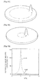
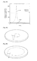
- FIG. 7 illustrates a structure of magnetic vortex and a gyrotropic field when the speed of the magnetic vortex core motion is 0
- FIG. 8 illustrates a structure of magnetic vortex and a gyrotropic field when the speed of the magnetic vortex core motion is 190 m/s
- FIG. 9 illustrates a structure of magnetic vortex and a gyrotropic field when the speed of the magnetic vortex core motion is 284 m/s
- FIG. 10 illustrates a structure of magnetic vortex and a gyrotropic field when the speed of the magnetic vortex core motion is 357 m/s.
- the x-axis indicates the size of the magnetic film and the diameter of the used magnetic film is 300 nm.
- the value '0' corresponds to a center of the magnetic film and the value ' ⁇ 150' indicates both ends of the magnetic film.
- the left scale of the y-axis indicates a ratio(M z /M s ) of the intensity of perpendicular magnetization direction component(M z ) of magnetic vortex core over the intensity of saturated perpendicular magnetization component(M s ), and the right scale of the y-axis indicates the intensity s of the gyrotropic field.
- the curves indicated by reference numerals 710a of FIG. 7 , 710b of FIG. 8 , 710c of FIG. 9 and 710d of FIG. 10 indicate components of perpendicular direction in the magnetic vortex structures.
- the curves indicated by reference numerals 720a of FIG. 7 , 720b of FIG. 8 , 720c of FIG. 9 and 720d of FIG. 10 indicate gyrotropic fields, respectively. As shown in FIG. 7 , when the speed of the magnetic vortex is 0, the gyrotropic field is near 0. However, as the speed of the magnetic vortex increases, the intensity of the gyrotropic fields 720b, 720c and 720d also increases as shown in FIGS. 8 through 10 .
- the magnetic vortex structure 710a is formed around a core of the magnetic film as shown in FIG. 7 , and then when the magnetic vortex starts to move, the magnetic vortex structure 710b is distorted due to the gyrotropic field 720b as shown in FIG. 8 .
- the magnetic vortex structure 720c having the M z component opposite to the original core orientation of the magnetic vortex as shown in FIG. 8 .
- the magnetic vortex structure 720d in which the M z component of the magnetic vortex in an opposite direction increases gradually.
- the distortion of the magnetic vortex structure around the magnetic vortex core is maximized so that a vortex-antivortex pair having a core orientation opposite to the perpendicular magnetization direction of the original core orientation of the magnetic vortex is generated.
- the generated antivortex meets with the original magnetic vortex and annihilates, so that only a newly created magnetic vortex remains. Since the newly created magnetic vortex has opposite core orientation to that of the original magnetic vortex core, a switching in the core orientation of the magnetic vortex occurs.
- the core orientation of the magnetic vortex is switched.
- the value of the gyrotropic field formed on a local area should reach the critical value.
- the critical value of the gyrotropic field causing the switching of the core orientation of the magnetic vortex corresponds to the critical speed of the magnetic vortex core. Accordingly, in order to switch the core orientation of the magnetic vortex, a predetermined current should be applied to the magnetic film in which the magnetic vortex is formed, thereby increasing the speed of the magnetic vortex core motion above the critical speed.
- a magnetic field antiparallel to the core orientation of the magnetic vortex formed in the magnetic free layer 140> i.e., a magnetic field having a direction perpendicular to the magnetic free layer.
- a current whose direction varies with time should be applied to record information in the magnetic recording element 100.
- a current whose direction is successively changed over time is applied.
- the direction of the applied current may be successively changed on a single plane, which is parallel to the top surface of the magnetic free layer 140.
- a current whose direction successively varies with time at a constant period or whose direction successively varies with time and intensity is constant is applied.
- a pulse current whose direction varies with time may be applied.
- the magnetic free layer 140 is formed in the shape of an elliptical plate or a rectangular plate, an elliptically polarized current rotating along a plane parallel to the top surface of the magnetic free layer 140 is applied. And in the case where the magnetic free layer 140 is formed in the shape of a disc or square plate, a circularly polarized current rotating along a plane parallel to the top surface of the magnetic free layer 140 is applied.
- the elliptically polarized current indicates a current whose magnitude over time and direction trace are elliptical
- a circularly polarized current is a special form of the elliptically polarized current and indicates a current whose the intensity over time and the direction trace are circular.
- the intensity of the circularly polarized current is always the same regardless of variation of time.
- the elliptically polarized current or circularly polarized current has a constant rotational period, and the elliptically polarized current or circularly polarized current applied to the magnetic free layer 140 from such a fact has a constant frequency.
- FIGS. 10 and 11 A process for applying the elliptically polarized current or circularly polarized current is shown in FIGS. 10 and 11 .
- FIG. 11 is a schematic view showing an electrode configuration of a magnetic recording element in a method for recording of information in a magnetic recording element
- FIG. 12 is a graph of voltage applied from the AC voltage source of FIG. 11 .
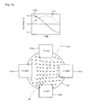
- the magnetic recording element has an electrode configuration shown in FIGS. 1 and 12 so as to apply a current to the magnetic free layer 140 thereof. That is, four electrodes 150a, 150b, 150c and 150d in ohmic contact with the magnetic free layer 140 are disposed at 90 intervals in a circumferential direction of the top surface of the magnetic free layer 140. Of four electrodes 150a, 150b, 150c and 150d, one pair of two electrodes facing each other and indicated by reference numerals 150a and 150b of FIG. 11 and another pair of two electrodes indicated by reference numerals 151a and 151b of FIG. 11 are connected to the AC voltage source. For the convenience of description, two electrodes 150a and 150b of FIG. 11 are called a first drive electrode pair and two electrodes 151a and 151b of FIG. 11 are called a second drive electrode pair.
- an elliptically polarized current flows through the magnetic free layer 140.
- sine- or cosine-wave AC voltages having the same frequency and a phase difference of 90° and having different amplitudes or sine- or cosine- wave voltages having the same frequency and amplitude and having a phase difference other than 90° are applied to the first drive electrode pair 150a and 150b and the second drive electrode pair 151a and 151b, an elliptically polarized current flows through the magnetic free layer 140.
- a circularly polarized current flows through the magnetic free layer 140.
- FIG. 12 One example for applying a circularly polarized current to the magnetic free layer 140 is shown in FIG. 12 . That is, a sine wave AC voltage indicated by reference numeral 1020 of FIG. 12 is applied to the first drive electrode pair 150a and 150b, and a cosine wave AC voltage indicated by reference numeral 1010 of FIG. 12 is applied to the second drive electrode pair 151a and 151b. As shown in FIG. 12 , the sine wave AC voltage indicated by reference numeral 1020 and the cosine wave AC voltage indicated by reference numeral 1010 have the same frequency and amplitude and have a phase difference of 90°.
- FIG. 13 is schematic views when a potential difference of +0.2 V is applied to the second drive electrode pair 151a and 151b and a potential difference of 0 V is applied to the first drive electrode pair 150a and 150b.
- +0.1 V is applied to the left electrode 151 b of the second drive electrode pair 151 a and 151 band 0.1 V is applied to the right electrode 151a.
- the direction of arrows shown in FIG. 13 indicates directions of a current at those portions.
- FIG. 14 is schematic views when a potential difference of +0.152 V is applied to the second drive electrode pair 151a and 151b and a potential difference of +0.1 V is applied to the first drive electrode pair 150a and 150b as time elapses.
- +0.086 V is applied to the left electrode 151 b of the second drive electrode pair 151 a and 151b and -0.086 V is applied to the right electrode 151a.
- +0.05 V is applied to the upper electrode 150a of the first drive electrode pair 150a and 150b and -0.05 V is applied to the lower electrode 150b.
- a direction perpendicular to the direction of a total current flowing through the magnetic free layer 140 is indicated by reference numeral 1120, which corresponds to a clockwise progression by 30° compared with the case of FIG. 13 .
- FIG. 15 is schematic views when a potential difference of +0.142 V is applied to both the first drive electrode pair 150a and 150b and the second drive electrode pair 151a and 151b over a further elapse of time.
- +0.071 V is applied to the upper electrode 150a of the first drive electrode pair 150a and 150b and -0.071 V is applied to the lower electrode 150b.
- +0.071 V is applied to the left electrode 151b of the second drive electrode pair 151a and 151b and -0.071 V is applied to the right electrode 151a.
- a direction perpendicular to the direction of a total current flowing through the magnetic free layer 140 is indicated by reference numeral 1130, which corresponds to a clockwise progression by 45° compared with the case of FIG. 13 .
- a circularly polarized current rotating clockwise at a constant frequency in a plane parallel to the top surface of the magnetic free layer 140 is called a right circularly polarized (RCP) current.
- RCP right circularly polarized
- LCP left circularly polarized
- a pulse voltage having a Gaussian distribution may be applied at a predetermined time difference to the first drive electrode pair 150a and 150b and the second drive electrode pair 151a and 151b. It is noted that the pulse voltage applied to the first drive electrode pair 150a and 150b and the second drive electrode pair 151a and 151b should be applied together for a predetermined time. If there no exists time applied together, a current whose direction is not changed over time may be applied.
- FIGS. 16 and 17 An example in which a current whose direction varies with time is applied to the magnetic free layer 140 by applying a pulse voltage having a Gaussian distribution to the first drive electrode pair 150a and 150b and the second drive electrode pair 151a and 151b is shown in FIGS. 16 and 17 .
- FIG. 16 is a schematic view of when a pulse voltage having a Gaussian distribution indicated by reference numeral 4410a is applied to the first drive electrode pair 150a and 150b and a pulse voltage having a Gaussian distribution indicated by reference numeral 4420a is applied to the second drive electrode pair 151a and 151b.
- a pulse voltage having a Gaussian distribution indicated by reference numeral 4410a is applied to the first drive electrode pair 150a and 150b
- a pulse voltage having a Gaussian distribution indicated by reference numeral 4420a is applied to the second drive electrode pair 151a and 151b.
- FIG. 17 is a schematic view of when a pulse voltage having a Gaussian distribution indicated by reference numeral 4410b is applied to the first drive electrode pair 150a and 150b and a pulse voltage having a Gaussian distribution indicated by reference numeral 4420b is applied to the second drive electrode pair 151a and 151b.
- a pulse voltage having a Gaussian distribution indicated by reference numeral 4410b is applied to the first drive electrode pair 150a and 150b and a pulse voltage having a Gaussian distribution indicated by reference numeral 4420b is applied to the second drive electrode pair 151a and 151b.
- a current having a configuration rotating clockwise is applied to the magnetic free layer 140 as shown in the right side of FIG. 17 .
- the magnitude and direction trace of current applied to the magnetic free layer 140 over time approach a circular shape when the applied pulse voltages having the same Gaussian distributions. That is, when an average value and a full width at half maximum (FWHM) of the two Gaussian distributions are the same, the magnitude and direction trace of current applied to the magnetic free layer 140 over time approach a circular shape. Also, when voltages having two Gaussian distributions are applied at time intervals 0.6671 times greater than FWHM, the magnitude and direction trace of current applied to the magnetic free layer 140 over time approach a circular shape. It is possible to apply a pulse voltage having a Gaussian distribution matched with the shape of the magnetic free layer 140 using the above characteristics.
- the magnetic free layer 140 is formed in the shape of a disk, it is preferable that a current having a trace close to a circular shape be applied to the magnetic free layer 140. Therefore, two pulse voltages having the same Gaussian distributions (the same average value and FWHM) are applied at time intervals of the 0.6671 times FWHM.
- Sine pulse or cosine pulse voltages having the same frequency and a phase difference may be applied to the first drive electrode pair 150a and 150b and the second drive electrode pair 151a and 151b.
- the voltages being applied as above results in an elliptically polarized current or a circularly polarized current being applied for a predetermined time.
- One example for applying voltages as above is shown in FIGS. 18 to 20 .
- FIG. 18 is a schematic view of when a sine pulse having a half period and indicated by reference numeral 1210a is applied to the second drive electrode pair 151a and 151b and a sine pulse having a half period and indicated by reference numeral 1220a is applied to the first drive electrode pair 150a and 150b.
- a circularly polarized current rotating counterclockwise by 90 degrees is applied to the magnetic free layer 140 as shown in the right side of FIG. 18.
- FIG. 19 is a schematic view of when a sine pulse having one period and indicated by reference numeral 1210b is applied to the second drive electrode pair 151a and 151b and a sine pulse having one period and indicated by reference numeral 1220b is applied to the first drive electrode pair 150a and 150b.
- a circularly polarized current rotating counterclockwise by 270 degrees is applied to the magnetic free layer 140 as shown in the right side of FIG. 19.
- FIG. 19 is a schematic view of when a sine pulse having one period and indicated by reference numeral 1210b is applied to the second drive electrode pair 151a and 151b and a sine pulse having one period and indicated by reference numeral 1220b is applied to the first drive electrode pair 150a and 150b.
- FIG. 20 is a schematic view of when a sine pulse having one and half period and indicated by reference numeral 1210c is applied to the second drive electrode pair 151a and 151b and a sine pulse having one and half period and indicated by reference numeral 1220c is applied to the first drive electrode pair 150a and 150b.
- a circularly polarized current rotating counterclockwise by 450 degrees is applied to the magnetic free layer 140 as shown in the right side of FIG. 20 .
- While the above arrangements show and describe a magnetic recording element having two pairs of drive electrodes in a way to apply to the magnetic free layer 140 a current chose direction varies with time, the arrangements are not limited thereto but can be similarly applied to a magnetic recording element having three or more pairs of drive electrodes. However, it is noted that frequencies of applied voltages in all the pairs of drive electrodes are preferably the same, the drive electrodes are formed along a circumference of the magnetic free layer 140 so as to apply a circularly polarized current, and a voltage having a constant phase difference should be applied to each drive electrode pair.
- FIGS. 21 and 22 are schematic views showing variations of a magnetic vortex core when a circularly polarized current is applied to a magnetic film in which the magnetic vortex core is formed upward from the top surface thereof.
- FIG. 21 is a case where an LCP current is applied
- FIG. 22 is a case where an RCP current is applied.
- frequencies and magnitudes of applied currents are the same.
- FIGS. 21 and 22 it can be seen that the case where the LCP current is applied to the magnetic film in which the magnetic vortex core is formed upward from the top surface thereof has a rotation radius much greater than the case where the RCP current is applied.
- a rotation radius of the magnetic vortex core over variation in frequency is shown in FIG. 23 .
- the diameter of the used magnetic film is 300nm.
- the x-axis corresponds to values normalizing a frequency of an applied current with an eigenfrequency of the magnetic vortex core formed in the magnetic film.
- the eigenfrequency ( ⁇ 0 ) of the magnetic vortex is defined as the following Equation:
- V 0 1 4 ⁇ ⁇ ⁇ ⁇ ⁇ M s ⁇ ⁇ 2 ⁇ 0
- M s is a saturation magnetization of the magnetic film
- ⁇ (0) is an initial susceptibility
- ⁇ is a gyromagnetic ratio
- ⁇ is a proportional constant. Since the gyromagnetic ratio and the proportional constant are constant values regardless of the forming material and shape of the magnetic film, the eigenfrequency of the magnetic vortex is inversely proportional to the initial susceptibility of the magnetic film in which the magnetic vortex is formed and is proportional to the square of saturation magnetization.
- the initial susceptibility is determined by the shape of the magnetic film
- the saturation magnetization is determined by the forming material of the magnetic film.
- the curve indicated by reference numeral 1410 of FIG. 23 corresponds to a case where an LCP current having a magnitude of 0.8mA is applied
- the curve indicated by reference numeral 1420 of FIG. 23 corresponds to a case where an RCP current having a magnitude of 0.8mA is applied.
- the case where the LCP current is applied to the magnetic film is larger in rotation radius of the magnetic vortex core than the case where the RCP current is applied. In particular, such a difference is large when the same frequency as the eigenfrequency of the magnetic vortex is applied.
- the speed of the magnetic vortex core according to variation of frequency is shown in FIG. 24 .
- the x-axis corresponds to values normalizing a frequency of an applied current with an eigenfrequency of the magnetic vortex core formed in the magnetic film.
- the curve indicated by reference numeral 1510 of FIG. 24 corresponds to a case where an LCP current having a magnitude of 0.8mA is applied, and the curve indicated by reference numeral 1520 of FIG. 24 corresponds to a case where an RCP current having a magnitude of 0.8mA is applied.
- a critical speed at which the magnetic vortex core is switched As shown in FIG.
- the case where an LCP current is applied is larger in the speed of the magnetic vortex core than the case where an RCP current is applied.
- such a difference is large when the same frequency as the eigenfrequency of the magnetic vortex is applied. Since currents having the same frequency are applied, the case (1510 of FIGS. 21 and 24 ) having a relatively large rotation radius is larger in the speed of the magnetic vortex core than the case having a relatively small rotation radius (1520 of FIGS. 22 and 24 ).
- FIG. 25 is a schematic view showing variation of the magnetic vortex core when an LCP current is applied
- FIG. 26 is a schematic view showing variation of the magnetic vortex core when an RCP current is applied
- FIG. 27 illustrates rotation radius of the magnetic vortex core according to variation of frequency
- FIG. 28 illustrates speed of the magnetic vortex core according to variation of frequency.
- the curve indicated by reference numeral 1710 of FIG. 27 and 1810 of FIG. 28 corresponds to a case of when an RCP current having a magnitude of 0.8mA is applied
- the curve indicated by reference numeral 1720 of FIG. 27 and 1820 of FIG. 28 corresponds to a case of when an LCP current having a magnitude of 0.8mA is applied.
- the case ( FIG. 25 ) where the LCP current is applied to the magnetic film has much smaller rotation radius than the case ( FIG. 26 ) where the RCP current is applied.
- the case (1710) where the LCP current is applied has a smaller rotation radius than the case (1720) where the RCP current is applied.
- the RCP current is applied to the magnetic free layer 140.
- the RCP current can easily switch the core orientation of the magnetic vortex formed downward from the top surface of the magnetic free layer 140 to an upward direction, but has a difficulty in switching the core orientation of the magnetic vortex formed in an upward direction from the top surface of the magnetic free layer 140 to a downward direction, as aforementioned.
- the core orientation of the magnetic vortex originally formed in a downward direction from the top surface of the magnetic free layer 140 is switched to an upward direction, and the core orientation of the magnetic vortex originally formed in an upward direction from the top surface of the magnetic free layer 140 is not switched but is maintained. Accordingly, it is possible to form the core orientation of the magnetic vortex in an upward direction from the top surface of the magnetic free layer 140 by applying the RCP current regardless of the core orientation of the magnetic vortex formed in the magnetic free layer 140.
- the LCP current is applied to the magnetic free layer 140.
- the core orientation of the magnetic vortex originally formed in an upward from the top surface of the magnetic free layer 140 is switched to a downward direction and the core orientation of the magnetic vortex originally formed in a downward from the top surface of the magnetic free layer 140 is not switched but is maintained. Accordingly, it is possible to form the core orientation of the magnetic vortex in a downward direction from the top surface of the magnetic free layer 140 by applying the LCP current regardless of the core orientation of the magnetic vortex formed in the magnetic free layer 140.
- FIG. 29 is a graph showing conditions of frequency and amplitude for switching the core orientation of the magnetic vortex formed in the magnetic free layer 140 from a downward direction of the top surface of the magnetic free layer 140 to an upward direction.
- the x-axis of FIG. 29 indicates a ratio of frequency (v) of an applied current over the eigenfrequency ( ⁇ 0 ) of the magnetic vortex formed in the magnetic free layer 140, and the y-axis indicates a magnitude (I) of the applied current.
- the curve indicated by reference numeral 1910 corresponds to a case where the RCP current is applied to the magnetic free layer 140
- the curve indicated by reference numeral 1920 corresponds to a case where the LCP current is applied to the magnetic free layer 140
- the curve indicated by reference numeral 1930 corresponds to a case where the linearly polarized current is applied to the magnetic free layer 140, respectively.
- the core orientation of the magnetic vortex formed in the magnetic free layer 140 is switched.
- the core orientation of the magnetic vortex formed in the magnetic free layer 140 can be switched from a downward direction of the top surface of the magnetic free layer 140 to an upward direction by applying the smallest current.
- the smallest current can be applied to switch the core orientation of the magnetic vortex formed in the magnetic free layer 140.
- the core orientation of the magnetic vortex formed in the magnetic free layer 140 can be switched from a downward direction of the top surface of the magnetic free layer 140 to an upward direction even with a current of about 0.8mA.
- the core orientation of the magnetic vortex formed in the magnetic free layer 140 can be switched from a downward direction of the top surface of the magnetic free layer 140 to an upward direction with a current of about 1.6mA.
- the case (1910) where the RCP current is applied can switch the core orientation of the magnetic vortex formed in the magnetic free layer 140 from the downward direction to the upward direction of the top surface of the magnetic free layer 140 with a current corresponding to half of the current in the case (1930).
- the magnitude of current for switching the core orientation of the magnetic vortex from the downward direction to the upward direction from the top surface of the magnetic free layer 140 has an eight-fold difference from the case (1910) where the RCP current is applied to the case (1920) where the LCP current is applied.
- a drawing showing a condition that the core orientation of the magnetic vortex formed in the magnetic free layer 140 is switched from the upward direction of the top surface of the magnetic free layer 140 to the downward direction is also similar to FIG. 29 .
- the LCP current should be applied so as to switch the core orientation of the magnetic vortex formed in the magnetic free layer 140 from the upward direction of the top surface of the magnetic free layer 140 to the downward direction with the smallest current.
- FIGS. 30 through 32 Conditions of frequency and amplitude for switching the core orientation of the magnetic vortex formed in the magnetic free layer 140 from the downward direction of the top surface of the magnetic free layer 140 to the upward direction by applying a pulse current to the magnetic free layer 140 are shown in FIGS. 30 through 32 .
- the magnetic free layer 140 used in FIGS. 30 through 32 is shaped in a disk having a radius of 150nm and a thickness of 20nm.
- FIG. 30 is a graph of when a pulse corresponding to one period of a circularly polarized current is applied
- FIG. 31 is a graph of when a pulse corresponding to half a period of a circularly polarized current is applied
- FIG. 32 is a graph of when a pulse having a Gaussian distribution is applied.
- the x-axis indicates a ratio of frequency ( ⁇ ) of an applied current over the eigenfrequency ( ⁇ 0 ) of the magnetic vortex formed in the magnetic free layer 140
- the y-axis indicates the magnitude (I) of an applied current
- the x-axis indicates a full width at half maximum (t FWHM ) and the y-axis indicates the magnitude (I) of an applied current.
- the graph indicated by reference numeral 4210 of FIG. 30 is a case where a sine pulse voltage having half a period is applied through the drive electrodes 150a, 150b, 151a and 151b and the voltage applied through the second drive electrodes 151a and 151b is delayed by 1/4 period such that a current rotating clockwise is applied to the magnetic free layer 140.
- the graph indicated by reference numeral 4220 of FIG. 30 corresponds to is a case where a sine pulse voltage having half a period is applied through the drive electrodes 150a, 150b, 151a and 151b and the voltage applied through the first drive electrodes 150a and 150b is delayed by 1/4 period such that a current rotating counterclockwise is applied to the magnetic free layer 140.
- the graph indicated by reference numeral 4230 of FIG. 30 corresponds to a case where a sine pulse voltage having half a period is applied through only the first drive electrodes 150a and 150b.
- the type of current applied to the magnetic free layer 140 corresponds to some of the RCP current as aforementioned
- the type of current applied to the magnetic free layer 140 corresponds to some of the LCP current as aforementioned
- the type of current applied to the magnetic free layer 140 corresponds to some of the linearly polarized current.
- the conditions on frequency and amplitude for switching the core orientation of the magnetic vortex formed in the magnetic free layer 140 from the downward direction of the top surface to the upward direction of the top surface are similar to those in FIG. 29 as a whole. That is, the case of reference numeral 4210 can switch the core orientation of the magnetic vortex formed in the magnetic free layer 140 from the downward direction of the top surface to the upward direction of the top surface with the smallest current, while the case of reference numeral 4220 can switch the core orientation of the magnetic vortex formed in the magnetic free layer 140 from the downward direction of the top surface to the upward direction of the top surface with the largest current.
- the case (4230) of the linearly polarized current the case of reference numeral 4210 can switch the core orientation of the magnetic vortex formed in the magnetic free layer 140 from the downward direction of the top surface to the upward direction of the top surface with a middle current between the current corresponding to the case indicated by reference numeral 4210 and the current corresponding to the case indicated by reference numeral 4220.
- a middle current between the current corresponding to the case indicated by reference numeral 4210 and the current corresponding to the case indicated by reference numeral 4220.
- ⁇ 0 the eigenfrequency of the magnetic vortex core but a frequency that has a minimum value somewhat smaller than the eigenfrequency and can switch the core orientation of the magnetic vortex formed in the magnetic free layer 140 from the downward direction of the top surface to the upward direction of the top surface is formed.
- a voltage greater than when a voltage having a continuous form is applied should be applied so as to switch the core orientation of the magnetic vortex formed in the magnetic free layer 140. Accordingly, the switching will be possible when a larger current is applied.
- the graph indicated by reference numeral 4310 of FIG. 31 is a case where a sine pulse voltage having one period is applied through the drive electrodes 150a, 150b, 151a and 151b and the voltage applied through the second drive electrodes 151a and 151b is delayed by 1/4 period such that a current rotating clockwise is applied to the magnetic free layer 140.
- the graph indicated by reference numeral 4320 of FIG. 31 corresponds to a case where a sine pulse voltage having one period is applied through the drive electrodes 150a, 150b, 151a and 151 b and the voltage applied through the first drive electrodes 150a and 150b is delayed by 1/4 period such that a current rotating counterclockwise is applied to the magnetic free layer 140.
- the graph indicated by reference numeral 4330 of FIG. 31 corresponds to a case where a sine pulse voltage having half a period is applied through only the first drive electrodes 150a and 150b.
- the resultant condition graph shown in of FIG. 31 is similar to that shown in FIG. 30 . That is, the case indicated by reference numeral 4310 and rotating clockwise can switch the core orientation of the magnetic vortex formed in the magnetic free layer 140 from the downward direction of the top surface to the upward direction of the top surface with the smallest current.
- a current much close to the circularly polarized current is applied to the magnetic free layer 140 compared with the case applying the sine pulse voltage having half a period, its magnitude becomes minimum at a frequency much close to the eigenfrequency.
- the magnitude of current switching the magnetic vortex core orientation is somewhat smaller than the case ( FIG. 30 ) where the sine pulse voltage having half a period is applied, resulting the graph of the vortex core switching condition close to that in FIG. 29 as a whole.
- the core orientation of the magnetic vortex formed in the magnetic free layer 140 can be switched by applying a small current, but a switching time increases. In consideration of this fact, it is possible to realize an optimum condition through a simulation.
- the graph indicated by reference numeral 4510 of FIG. 32 corresponds to a case where a pulse voltage having a Gaussian distribution is applied through the drive electrodes 150a, 150b, 151a and 151 b and the voltage applied through the second drive electrodes 151a and 151b is delayed by a time interval of 0.6671 times greater than FWHM such that a current 4515 rotating clockwise is applied to the magnetic free layer 140.
- the graph indicated by reference numeral 4530 of FIG. 32 corresponds to a case where a pulse voltage having a linearly polarized Gaussian distribution is applied through only the first drive electrodes 150a and 150b.
- the shape of the magnetic free layer 140 used in FIG. 32 is a circle
- two pulses applied in reference numerals 4510 and 4520 are the same and are applied at a time interval of 0.6671 times FWHM as aforementioned. This is because the current under the above conditions is the closest to a circle, power consumption is minimized and a difference between currents in the respective cases is apparent.
- the cases 4510 and 4515 where the current rotating clockwise is applied can switch the core orientation of the magnetic vortex formed in the magnetic free layer 140 from the downward direction of the top surface to the upward direction of the top surface with the smallest current.
- power consumption necessary for switching the core orientation of the magnetic vortex formed in the magnetic free layer 140 becomes minimum. That is, it is preferable that pulse voltages having two Gaussian distributions are applied at a time delay of 0.6671 times FWHM through the drive electrodes 150a, 150b, 151a and 151b having a FWHM of 0.3748 times the ⁇ 0 of the magnetic vortex formed in the magnetic free layer 140.
- the core orientation of the magnetic vortex formed in the magnetic free layer 140 may be switched not once but several times by applying a pulse voltage having a Gaussian distribution.
- a voltage having a Gaussian distribution is applied several times, the switching time increases, but it becomes possible to switch the core orientation of the magnetic vortex formed in the magnetic free layer 140 even with a small current. Accordingly, an optimal condition is realized through a simulation. At this time, in order to minimize power consumption, an interval of each pulse is designed to become the resonance period of the magnetic vortex formed in the magnetic free layer 140.
- the case where the pulse current is applied can reduce power consumption by applying the current rotating over time rather than applying the linearly polarized current. Also, it is selectable to form the core orientation of the magnetic vortex formed in the magnetic free layer 140 in the upward direction of the top surface or the downward direction of the top surface and thus the perpendicular magnetization of the magnetic vortex can be positioned in a desired direction.
- the condition for switching the core orientation of the magnetic vortex formed in the magnetic free layer 140 from the upward direction of the top surface to the downward direction in the case where the pulse current is applied is opposite. That is, when the pulse current rotating counterclockwise is applied to the magnetic free layer 140, it becomes possible to switch the core orientation of the magnetic vortex formed in the magnetic free layer 140 from the upward direction of the top surface to the downward direction with the smallest current.
- a value of "0" or "1" is assigned according to the core orientation of the magnetic vortex formed in the magnetic free layer 140.
- the core orientation of the magnetic vortex formed in the magnetic free layer 140 is formed in the upward direction or downward direction of the top surface by applying a current whose direction varies with time to the magnetic free layer 140
- a case where a magnetic field whose direction varies with time is applied to the magnetic free layer 140 also obtains a similar result.
- the direction of the magnetic field as applied may be also successively varied with time.
- a magnetic field whose direction is successively varied with one plane may be applied. This plane may be one parallel to the top surface of the magnetic free layer 140.
- a magnetic field whose direction is successively changed at a constant period over time, or whose direction is successively varied with time but magnitude is always constant may be applied.
- a pulse magnetic field whose direction varies with time may be applied.
- an elliptically polarized magnetic field rotating along a plane parallel to the top surface of the magnetic free layer 140 is applied.
- an elliptically polarized magnetic field rotating along a plane parallel to the top surface of the magnetic free layer 140 is applied.
- the configuration of the drive electrodes should be different than the configuration of the drive electrodes of when a current is applied.
- drive electrodes may be disposed to cross each other at an angle of 90 on or beneath the magnetic free layer 140.
- an elliptically polarized magnetic field is applied to the magnetic free layer 140.
- sine- or cosine- wave currents having the same frequency, a phase difference of 90 and a different amplitude are applied to two drive electrodes 450 and 451, or when sine- or cosine- wave currents having the same frequency and amplitude and having a phase difference other than 90 are applied to two drive electrodes 450 and 451, an elliptically polarized magnetic field is applied to the magnetic free layer 140.
- a circularly polarized magnetic field is applied to the magnetic free layer 140.
- a pulse magnetic field whose direction varies with time may be applied to the magnetic free layer 140.
- two pulse currents should be applied together for a predetermined duration time.
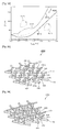
- FIG. 33 is a schematic perspective view of an MRAM 2900 used in a method for recording information.
- the MRAM 2900 includes an array of magnetic recording elements 100 of FIG. 1 arranged in rows and columns.
- the respective magnetic recording elements 100 are connected to each other through drive electrodes 150a, 150b, 151a and 151b formed on a magnetic free layer 140, and a read electrode 110 formed under a magnetic pinned layer 120.
- the drive electrodes 150a, 150b, 151a and 151b are composed of four electrodes. Of the four drive electrodes 150a, 150b, 151a and 151b, two electrodes 150a and 150b facing each other form one electrode pair 150, and the other two electrodes 151a and 151b facing each other form another electrode pair 151.
- the read electrode 110 is composed of a single electrode, and extends in a direction between the drive electrode pairs 150 and 151. That is, the read electrode 110 is disposed at an angle of 45° with respect to the two drive electrode pairs 150 and 151. At this time, the read electrodes 110 are arranged in the same direction.
- the respective magnetic recording elements form the array in a configuration that the adjacent magnetic recording elements share the drive electrode and the read electrode.
- the drive electrode indicated by reference numeral 150b of the drive electrodes 150a, 150b, 151a and 151b included in the magnetic recording element indicated by reference numeral 100 is connected to the magnetic recording element indicated by reference numeral 101. Therefore, the magnetic recording elements indicated by reference numeral 100 and 101 share the drive electrode indicated by reference numeral 150b.
- the magnetic recording elements indicated by reference numerals 100 and 102 share the drive electrode indicated by reference numeral 151b.
- the read electrode 110 included in the magnetic recording element indicated by reference numeral 100 is connected to the magnetic recording element indicated by reference numeral 103 that is the second closest magnetic recording element. That is, the magnetic recording elements indicated by reference numerals 100 and 103 share the read electrode indicated by reference numeral 110.
- FIG. 34 is a schematic perspective view of an MRAM 3200 used in a method for recording information according to an embodiment of the present invention.
- the magnetic recording element forming the MRAM 3200 of FIG. 34 is the magnetic recording element 400 of FIG. 5 . That is, in the MRAM 3200 of FIG. 34 , the magnetic recording elements 400 of FIG. 5 are arranged in rows and columns, and the respective magnetic recording elements 400 form an array so as to share the drive electrodes 450 and 451 and the read electrode 410 with the magnetic recording elements 400 adjacent thereto.
- the MRAM 3200 of FIG. 34 only differs in the drive electrode structure from the MRAM 2900 of FIG. 33 , and other parts correspond to those of the MRAM 2900 of FIG. 33 .
- the drive electrodes 450 and 451 of the MRAM 3200 of FIG. 34 are disposed on the magnetic free layer 440 in a configuration to cross each other at a right angle. As illustrated in FIG. 33 , the drive electrodes 450 and 451 connect the closet magnetic recording elements, and the read electrode 410 connects the second closest magnetic recording elements.
- the MRAM including an array of the magnetic recording elements of FIG. 5 arranged in rows and columns has not only a configuration of FIG. 34 , but also another configuration where the read electrode 410 connects the closest magnetic recording elements and the drive electrodes connect the second closest magnetic recording elements.
- Number of the drive electrodes may be three or more. Even though the number of the drive electrodes is two, both the two drive electrodes may be formed on the undersurface of the magnetic recording element 440 or formed on the top surface and the undersurface of the magnetic free layer, respectively, which differs the configuration of FIG. 34 .
- the magnetic recording elements may cross each other at an angle other than 90°.
- Each of the magnetic recording elements 100, 400 of the MRAMs 2900 and 3200 in FIGS. 32 and 33 should exhibit the same characteristics regardless of its location.
- each of the magnetic recording elements 100, 400 of the MRAMs 2900 and 3200 should exhibit the same response to a current or magnetic field applied to store, record and read information. Therefore, the magnetic recording elements 100, 400, 500 forming the MRAM 2900, 3200 should have the same shape and thickness, and be formed of the same material.
- the MRAM 2900, 3200 is configured such that the magnetic vortexes formed in the magnetic free layers 140 and 440 included in all the magnetic recording elements of the MRAM 2900, 3200 may have the same eigenfrequency. Furthermore, the MRAM 2900, 3200 should be configured such that the rotation direction of the parallel magnetization arranged in parallel with the top surface of the magnetic free layer and arranged around the magnetic vortex core formed in the magnetic free layer 140, 440 may be the same in all the magnetic recording elements.
- FIG. 35 is a flowchart illustrating a method for recording information in an MRAM according to an embodiment of the present invention. For reference, it will be described that a method for recording information in an MRAM to be described later is realized using the MRAM 2900 of FIG. 33 . However, other MRAMs are also available if they include an array of magnetic recording elements arranged in rows and columns and each of the magnetic recording element includes a magnetic free layer with a magnetic vortex formed, and a plurality of drive electrode pairs disposed to form an ohmic contact with the magnetic layer and connected to the adjacent magnetic recording elements.
- an MRAM 2900 is prepared, in which magnetic recording elements 100 are arranged in rows and columns.
- the magnetic recording element 100 includes a magnetic free layer 140 with a magnetic vortex formed, and four drive electrodes 150a, 150b, 151 a and 151b disposed to form an ohmic contact with the magnetic free layer 140.
- the MRAM 2900 form an array by sharing the drive electrodes 150a, 150b, 151 a and 151b with the adjacent magnetic recording elements 100, as illustrated in FIG. 33 .
- the magnetic free layer 140 provided in the magnetic recording element 100 is formed so as to have the diameter and thickness corresponding to the region II of FIG. 2 .
- the four drive electrodes 150a, 150b, 151 a and 151b two electrodes 150a and 150b facing each other form one drive electrode pair, and the other two electrodes 151a and 151b facing each other form another drive electrode pair.
- a voltage is applied to the two drive electrode pairs 150 and 151 included in the magnetic recording element that is selected to record information.
- the core orientation of the magnetic vortex formed in the magnetic free layer of the selected magnetic recording element is changed to a desired direction by applying a current of which a direction varies with time to the magnetic free layer of the selected magnetic recording element.
- the core orientation of the magnetic vortex formed in the magnetic free layers included in the other unselected magnetic recording elements are maintained constant.
- the magnetic vortex moves when a current is applied to the magnetic free layer 140 with the magnetic vortex formed. Then, when the moving speed of the magnetic vortex core is beyond a critical speed allowing the core orientation of the magnetic vortex to be switched, the core orientation of the magnetic vortex is switched.
- FIG. 36 illustrates a selected magnetic recording element and an unselected magnetic recording element in a method for recording information in an MRAM according to the present invention.
- a current may be applied to an unselected magnetic recording element 3520 besides a selected magnetic recording element 3510 to which information is to be recorded because MRAMs are connected by the drive electrode pair. Therefore, it is required that the core orientation of the magnetic vortex formed in the magnetic free layer of the magnetic recording element 3510 to which a user will record information should be formed in a desired direction whereas the core orientation of the magnetic vortex formed in the magnetic free layer of the unselected magnetic recording element 3520 should not be changed but maintained constant even if the current is applied.
- the curve indicated by reference numeral 1910 denotes the case of applying an RCP current to the magnetic free layer 140
- the curve indicated by reference numeral 1920 denotes the case of applying an LCP current to the magnetic free layer 140
- the curve indicated by reference numeral 1930 denotes the case of applying a linearly polarized current to the magnetic free layer 140.
- the core orientation of the magnetic vortex formed in the magnetic free layer 140 can be switched from a downward direction to an upward direction with respect to the top surface of the magnetic free layer 140 using only a current of which magnitude is half the magnitude of the current required in the case (see the curve 1920) of applying the linearly polarized current.
- sine- or cosine- wave AC voltages having a phase difference of 90° and the same amplitude and frequency are applied to the two drive electrode pairs 150 and 151 provided in the magnetic recording element indicated by reference numeral 3510. Resultantly, the circularly polarized current flows through the magnetic recording element indicated by reference numeral 3510 but the linearly polarized current flows through the magnetic recording element indicated by reference numeral 3520.
- the applied current should have the magnitude allowing the core orientation of the magnetic vortex formed in the magnetic free layer of the selected magnetic recording element 3510 to be switched from a downward direction to an upward direction with respect to the top surface of the magnetic free layer at a specific frequency.
- the magnitude of applied voltage is adjusted to the condition that the core orientation of the magnetic vortex is not switched in the case where the linearly polarized current is applied. That is, the magnitude of voltage applied through the drive electrode pairs 150 and 151 is adjusted so that a current of which magnitude ranges between the curves 1910 and 1920 of FIG. 29 is applied to the magnetic free layer.
- the core orientation of the magnetic vortex formed in the magnetic free layer of the selected magnetic recording element 3510 is switched, but the core orientation of the magnetic vortex formed in the magnetic free layer of the unselected magnetic recording element 3520 is not switched. That is, information may be recorded only in the selected magnetic recording element 3510.
- a voltage having the same frequency as the eigenfrequency of the magnetic vortex formed in the magnetic free layer is applied to the drive electrode pairs 150 and 151 in order that a frequency of the current applied to the magnetic free layer may be equal to the eigenfrequency of the magnetic vortex formed in the magnetic free layer. The reason is to reduce power consumption.
- the frequency and amplitude conditions in FIG. 29 for switching the core orientation of the magnetic vortex are similar to those of the case of switching the core orientation of the magnetic vortex formed in the magnetic free layer by applying an elliptically polarized current to the magnetic free layer. Accordingly, the application of the elliptically polarized current provides similar results to the above illustrated in FIG. 29 . Even if the applied current is not a circularly polarized current or an elliptically polarized current, it is possible to achieve the similar effect by applying a current of which a direction varies with time.
- the core orientation of the magnetic vortex formed in the magnetic free layer of the magnetic recording element 3510 that is selected to store information can be formed in a desired direction even though a pulse current of which a direction varies with time is applied to the magnetic free layer.
- the above-described conditions in FIGS. 30 through 32 are available to record information only in the selected magnetic recording element 3510 by applying the pulse current to the magnetic free layer 140.
- a current having a magnitude ranging between the curve indicated by reference numeral 4210 and the curve indicated by reference numeral 4230, a current having a magnitude ranging between the curve indicated by reference numeral 4310 and the curve indicated by reference numeral 4330, or a current having a magnitude ranging between the curve indicated by reference numeral 4510 and the curve indicated by reference numeral 4530 may be applied to record information only in the selected magnetic recording element 3510 by applying the pulse current to the magnetic free layer 140.
- the pulse current corresponding to a portion of a circularly or elliptically polarized current it should have a frequency equal to the eigenfrequency of the magnetic free layer 140.
- Only the core orientation of the magnetic vortex formed in the magnetic free layer of the selected magnetic recording element 3510 can be switched even by applying a linearly polarized current to the magnetic free layer provided in the selected magnetic recording element 3510.
- a linearly polarized current flows through both the selected magnetic recording element 35210 and the unselected magnetic recording element 3520.
- the frequency of the AC voltage applied to the drive electrode pairs 150 and 151 be equal to the eigenfrequency of the magnetic vortex.
- the current having the magnitude corresponding to the sum of the linearly in-phase currents flows through the selected magnetic recording element 3510, which is greater than the magnitude of current flowing through the unselected magnetic recording element 3520.
- the linearly current having the magnitude that can switch the core orientation of the magnetic vortex may flow through the selected magnetic recording element 3510, and the linearly current having the magnitude that cannot switch the core orientation of the magnetic vortex may flow through the unselected magnetic recording element 3520.
- FIG. 37 illustrates a variation in current density according to a position in the magnetic free layer 140 when the linearly current is applied.
- the x-axis of FIG. 37 represents the position in the magnetic free layer 140 provided in the selected magnetic recording element.
- a magnetic layer indicated by reference numeral 3610 has a diameter of 600 nm.
- the current density of the linearly polarized current applied to the magnetic free layer provided in the selected magnetic recording element 3510 is greater than the current density of the linearly polarized current applied to the magnetic free layer provided in the unselected magnetic recording element 3520.
- the magnitude of current applied to the magnetic free layer provided in the selected magnetic recording element 3510 is set to be higher than the magnitudes corresponding to the curve 1930 of FIG. 29 , the curve 4230 of FIG. 30 , the curve 4330 of FIG. 31 , and the curve 4530 of FIG. 32 . That is, the magnitude of current applied to the magnetic free layer provided in the selected magnetic recording element 3510 should be equal to or greater than the magnitude of current that can switch the magnetic vortex core during the application of the linearly current.
- the magnitude of current applied to the magnetic free layer provided in the unselected magnetic recording element 3520 is set to be smaller than the magnitudes corresponding to the curve 1930 of FIG. 29 , the curve 4230 of FIG.
- the magnitude of current applied to the magnetic free layer provided in the unselected magnetic recording element 3520 is set to be smaller than the magnitude of current allowing the magnetic vortex core to be switched during the application of the linearly polarized current.
- the current having the magnitude corresponding to the above condition flows as illustrated in FIG. 37 , and thus information can be recorded only in the selected magnetic recording element 3510 by applying this current.
- the drive electrodes provided in the magnetic recording element of the MRAM are not in ohmic contact with the magnetic free layer, but the drive electrodes 450 and 451 are formed on or beneath the magnetic free layer in a configuration to cross each other, as illustrated in FIG. 34 .
- the drive electrodes 450 and 451 may be disposed to cross each other at a right angle.
- a magnetic field is applied through the drive electrodes 450 and 451 having the above configuration, thus forming the core orientation of the magnetic vortex formed in the magnetic free layer of the selected magnetic recording element in a desired direction.
- the core orientation of the magnetic vortex formed in the magnetic free layers of the other unselected magnetic recording elements may be maintained equal to the core orientation of the magnetic vortex of the previous state before the application of the magnetic field.
- An elliptically polarized magnetic field may be applied by applying sine- or cosine-wave AC currents having a predetermined phase difference and the same frequency to the two drive electrodes 450 and 451.
- sine- or cosine-wave AC currents having a phase difference of 90° and the same amplitude and frequency are applied to the two drive electrodes 450 and 451, a circularly magnetic field is applied to the magnetic free layer.
- in-phase AC currents having the same frequency are applied to the two drive electrodes 450 and 451, a linearly polarized magnetic field is applied to the magnetic free layer.
- sine- or cosine-wave AC currents having a predetermined phase difference and the same frequency may be applied to the two drive electrodes 450 and 451.
- a tine interval between the two successive sine- or cosine-wave AC currents applied through the two drive electrodes 450 and 451 may be a quarter of a period.
- the voltage applied to the magnetic free layer has a portion of a circularly polarized magnetic field
- two pulse currents applied through the two drive electrodes 450 and 451 may have a predetermined time internal therebetween. However, the two pulse currents should be applied together for at least a predetermined duration so as to apply a pulse magnetic field to the magnetic free layer.
- the applied current may be a pulse current having a Gaussian distribution.
- the pulse currents having Gaussian distributions, which are applied through the two drive electrodes 450 and 451, are identical to each other in an average value and FWHM, and a time interval between the two pulse currents may be 0.6671 times the FWHM. If the pulse currents are applied in this manner, magnitude and direction traces of the voltage applied to the magnetic free layer over time approach a circular form.
- Frequency and amplitude conditions which allow the core orientation of the magnetic vortex to be switched when a linearly polarized magnetic field or a circularly magnetic field is applied, are similar to the conditions of FIG. 7 . Furthermore, conditions allowing the core orientation of the magnetic vortex to be switched when a pulse magnetic field is applied are similar to the conditions of FIGS. 29 through 32 . Consequently, by the use of such conditions, the core orientation of the magnetic vortex formed in the magnetic free layer of the selected magnetic recording element can be formed in a desired direction, and the core orientation of the magnetic vortex formed in the magnetic free layers included in the other unselected magnetic recording elements can be maintained constant.
Landscapes
- Engineering & Computer Science (AREA)
- Computer Hardware Design (AREA)
- Hall/Mr Elements (AREA)
Claims (11)
- Verfahren zum Aufzeichnen von Informationen in einem Magnetaufzeichnungselement (100), umfassend:Herstellen des Magnetaufzeichnungselements mit einer magnetfreien Schicht (140), in der ein Magnetwirbel (310) gebildet wird;Umschalten einer Kern- (320a; 320b) Orientierung eines Magnetwirbels, der in der magnetfreien Schicht gebildet wird, in eine Richtung nach oben oder Richtung nach unten von einer Oberseite der magnetfreien Schicht; undZuordnen von "0" oder "1" entsprechend der Richtung der Kernorientierung des Magnetwirbels, der in der magnetfreien Schicht gebildet wird,dadurch gekennzeichnet, dass der Schritt des Umschaltens einer Kernorientierung eines Magnetwirbels den Schritt des Anlegens eines Magnetfeldes an die magnetfreie Schicht umfasst, dessen Richtung im Laufe der Zeit variiert, und dass das Magnetaufzeichnungselement (400) ferner zwei Ansteuerungselektroden (450, 451) umfasst, die einander zumindest auf oder unterhalb der magnetfreien schicht senkrecht kreuzen.
- Verfahren nach Anspruch 1, wobei das Umschalten einer Kernorientierung eines Magnetwirbels (310), der in der magnetfreien Schicht (140) gebildet wird, in eine Richtung nach oben oder Richtung nach unten von einer Oberseite der magnetfreien Schicht umfasst:wenn beabsichtigt ist, die Kernorientierung des Magnetwirbels zur Richtung nach oben von der Oberseite der magnetfreien Schicht umzuschalten, Anlegen eines Magnetfeldes, dessen Richtung im Laufe der Zeit zu der magnetfreien Schicht, in der der Magnetwirbel gebildet wird, derart variiert, dass eine Geschwindigkeit des Magnetwirbelkerns mit der Kernorientierung von der Oberseite der magnetfreien Schicht nach unten über einer kritischen Geschwindigkeit liegt und eine Geschwindigkeit des Magnetwirbelkerns mit der Kernorientierung von der Oberseite der magnetfreien Schicht nach oben unter der kritischen Geschwindigkeit liegt, undwenn beabsichtigt ist, die Kernorientierung des Magnetwirbels zur Richtung nach unten von der Oberseite der magnetfreien Schicht umzuschalten, Anlegen eines Magnetfeldes, dessen Richtung im Laufe der Zeit zu der magnetfreien Schicht, in der der Magnetwirbel gebildet wird, derart variiert, dass eine Geschwindigkeit des Magnetwirbelkerns mit der Kernorientierung von der Oberseite der magnetfreien Schicht nach unten unter einer kritischen Geschwindigkeit liegt und eine Geschwindigkeit des Magnetwirbelkerns mit der Kernorientierung von der Oberseite der magnetfreien Schicht nach oben über der kritischen Geschwindigkeit liegt.
- Verfahren nach Anspruch 1, wobei die magnetfreie Schicht (140) in einer elliptischen Platte von rechteckiger Plattenform gebildet ist, wobei das Umschalten einer Kernorientierung eines Magnetwirbels (310), der in der magnetfreien Schicht (140) gebildet wird, in eine Richtung nach oben oder Richtung nach unten von einer Oberseite der magnetfreien Schicht das Anlegen eines elliptisch polarisierten Magnetfeldes an die magnetfreie Schicht umfasst, in der der Magnetwirbel gebildet ist.
- Verfahren nach Anspruch 1, wobei die magnetfreie Schicht (140) in einer Scheiben- oder Quadratplattenform gebildet ist, wobei das Umschalten einer Kernorientierung eines Magnetwirbels (310), der in der magnetfreien Schicht (140) gebildet wird, in eine Richtung nach oben oder Richtung nach unten von einer Oberseite der magnetfreien Schicht das Anlegen eines kreisförmig polarisierten Magnetfeldes an die magnetfreie Schicht umfasst, in der der Magnetwirbel gebildet ist.
- Verfahren nach Anspruch 3 oder 4, wobei das angelegte Magnetfeld eine Frequenz aufweist, die dieselbe wie eine Eigenfrequenz des Magnetwirbels (310) ist, der in der magnetfreien Schicht (140) gebildet wird.
- Verfahren nach Anspruch 1, wobei das Umschalten einer Kernorientierung eines Magnetwirbels (310), der in der magnetfreien Schicht (140) gebildet wird, in eine Richtung nach oben oder Richtung nach unten von einer Oberseite der magnetfreien Schicht umfasst:Anlegen eines Magnetfeldes, das im Uhrzeigersinn in Bezug auf die Oberseite der magnetfreien Schicht dreht, um die Kernorientierung des Magnetwirbels, der in der magnetfreien Schicht gebildet wird, in die Richtung nach oben von der Oberseite der magnetfreien Schicht umzuschalten, oderAnlegen eines Magnetfeldes, das gegen den Uhrzeigersinn in Bezug auf die Oberseite der magnetfreien Schicht dreht, um die Kernorientierung des Magnetwirbels, der in der magnetfreien Schicht gebildet wird, in die Richtung nach unten von der Oberseite der magnetfreien Schicht umzuschalten.
- Verfahren nach Anspruch 6, wobei
das Magnetfeld, das im Uhrzeigersinn dreht, ein rechts kreisförmig polarisiertes Magnetfeld oder ein rechts elliptisch polarisiertes Magnetfeld ist und
das Magnetfeld, das gegen den Uhrzeigersinn dreht, ein links kreisförmig polarisiertes Magnetfeld oder ein links elliptisch polarisiertes Magnetfeld ist. - Verfahren nach Anspruch 1, wobei das Umschalten einer Kernorientierung eines Magnetwirbels (310), der in der magnetfreien Schicht (140) gebildet wird, in eine Richtung nach oben oder Richtung nach unten von einer Oberseite der magnetfreien Schicht das Anlegen von Sinus- oder Kosinuswellen-Wechselströmen mit einer Phasendifferenz und derselben Frequenz an die zwei Ansteuerungselektroden umfasst.
- Verfahren nach Anspruch 8, wobei die angelegten Sinus- oder Kosinuswellen-Wechselströme dieselbe Amplitude und eine Phasendifferenz von 90° haben,
wobei die angelegten Sinus- oder Kosinuswellen-Wechselströme eine Frequenz haben, die dieselbe ist wie eine Eigenfrequenz des Magnetwirbels, der in der magnetfreien Schicht gebildet wird. - Verfahren nach Anspruch 1, wobei das Umschalten einer Kernorientierung eines Magnetwirbels (310), der in der magnetfreien Schicht (140) gebildet wird, in eine Richtung nach oben oder Richtung nach unten von einer Oberseite der magnetfreien Schicht das Anlegen von Pulsströmen mit zwei Gaußschen Verteilungen in einem Zeitintervall an die zwei Ansteuerungselektroden umfasst.
- Verfahren nach Anspruch 10, wobei das Umschalten einer Kernorientierung eines Magnetwirbels (310), der in der magnetfreien Schicht gebildet wird, in eine Richtung nach oben oder Richtung nach unten von einer Oberseite der magnetfreien Schicht das Anlegen von zwei oder mehr Pulsströmen in einem Zeitintervall durch die zwei Ansteuerungselektroden umfasst, wobei das Zeitintervall als ein Reziprokwert einer Eigenfrequenz des Magnetwirbels, der in der magnetfreien Schicht gebildet wird, eingestellt ist.
Applications Claiming Priority (3)
| Application Number | Priority Date | Filing Date | Title |
|---|---|---|---|
| KR1020070105590A KR100931547B1 (ko) | 2007-10-19 | 2007-10-19 | 자기기록소자의 정보기록방법 |
| KR1020070105600A KR100931555B1 (ko) | 2007-10-19 | 2007-10-19 | 자기 랜덤 액세스 메모리의 정보기록방법 |
| PCT/KR2008/006150 WO2009051441A1 (en) | 2007-10-19 | 2008-10-17 | Method for recording of information in magnetic recording element and method for recording of information in magnetic random access memory |
Publications (3)
| Publication Number | Publication Date |
|---|---|
| EP2206119A1 EP2206119A1 (de) | 2010-07-14 |
| EP2206119A4 EP2206119A4 (de) | 2010-11-10 |
| EP2206119B1 true EP2206119B1 (de) | 2012-12-05 |
Family
ID=40567582
Family Applications (1)
| Application Number | Title | Priority Date | Filing Date |
|---|---|---|---|
| EP08838620A Active EP2206119B1 (de) | 2007-10-19 | 2008-10-17 | Verfahren zum aufzeichnen von informationen in einem magnetischen aufzeichnungselement und verfahren zum aufzeichnen von informationen in einem magnetischen direktzugriffsspeicher |
Country Status (3)
| Country | Link |
|---|---|
| US (1) | US8300453B2 (de) |
| EP (1) | EP2206119B1 (de) |
| WO (1) | WO2009051441A1 (de) |
Families Citing this family (6)
| Publication number | Priority date | Publication date | Assignee | Title |
|---|---|---|---|---|
| WO2009051442A2 (en) * | 2007-10-19 | 2009-04-23 | Snu R & Db Foundation | Method for read-out of information in magnetic recording element and method for read-out of information in magnetic random access memory |
| US8324696B2 (en) | 2007-10-19 | 2012-12-04 | Snu R&Db Foundation | Ultrafast magnetic recording element and nonvolatile magnetic random access memory using the magnetic recording element |
| US8981503B2 (en) | 2012-03-16 | 2015-03-17 | Headway Technologies, Inc. | STT-MRAM reference layer having substantially reduced stray field and consisting of a single magnetic domain |
| CN106030840B (zh) * | 2014-03-25 | 2019-03-01 | 英特尔公司 | 磁畴壁逻辑器件及互连 |
| US9541605B1 (en) * | 2015-12-15 | 2017-01-10 | International Business Machines Corporation | Magnetic tunnel junction loaded ring oscillators for MRAM characterization |
| US12170162B2 (en) * | 2020-12-08 | 2024-12-17 | Jannier M. Roiz-Wilson | Warped magnetic tunnel junctions and bit-patterned media |
Family Cites Families (10)
| Publication number | Priority date | Publication date | Assignee | Title |
|---|---|---|---|---|
| JPH1196515A (ja) | 1997-09-18 | 1999-04-09 | Fujitsu Ltd | Gmr磁気センサ、その製造方法、および磁気ヘッド |
| JP2002175623A (ja) | 2000-12-07 | 2002-06-21 | Matsushita Electric Ind Co Ltd | 磁気記録媒体、マスター情報磁気記録方法、マスター情報担体、磁気記録再生装置およびハードディスクドライブ |
| JP3482469B2 (ja) * | 2001-05-21 | 2003-12-22 | 北海道大学長 | 磁気記憶素子、磁気メモリ、磁気記録方法、磁気記憶素子の製造方法、及び磁気メモリの製造方法 |
| DE10149737A1 (de) * | 2001-10-09 | 2003-04-24 | Infineon Technologies Ag | Halbleiterspeicher mit sich kreuzenden Wort- und Bitleitungen, an denen magnetoresistive Speicherzellen angeordnet sind |
| JP3987924B2 (ja) | 2002-12-13 | 2007-10-10 | 国立大学法人大阪大学 | 磁性メモリアレイ、磁性メモリアレイの書き込み方法及び磁性メモリアレイの読み出し方法 |
| US6967863B2 (en) | 2004-02-25 | 2005-11-22 | Grandis, Inc. | Perpendicular magnetization magnetic element utilizing spin transfer |
| US7072208B2 (en) * | 2004-07-28 | 2006-07-04 | Headway Technologies, Inc. | Vortex magnetic random access memory |
| US7593184B2 (en) * | 2005-10-24 | 2009-09-22 | Seagate Technology Llc | Rotating write field generated by circulating domain walls in a magnetic ring: a DC-driven high-frequency oscillator |
| US7952915B2 (en) * | 2006-03-02 | 2011-05-31 | Kyoto University | Core-rotating element of ferromagnetic dot and information memory element using the core of ferromagnetic dot |
| US7898849B2 (en) * | 2007-12-05 | 2011-03-01 | Seagate Technology, Llc | Compound cell spin-torque magnetic random access memory |
-
2008
- 2008-10-17 EP EP08838620A patent/EP2206119B1/de active Active
- 2008-10-17 US US12/738,655 patent/US8300453B2/en active Active
- 2008-10-17 WO PCT/KR2008/006150 patent/WO2009051441A1/en not_active Ceased
Also Published As
| Publication number | Publication date |
|---|---|
| EP2206119A1 (de) | 2010-07-14 |
| EP2206119A4 (de) | 2010-11-10 |
| US20100290281A1 (en) | 2010-11-18 |
| WO2009051441A1 (en) | 2009-04-23 |
| US8300453B2 (en) | 2012-10-30 |
Similar Documents
| Publication | Publication Date | Title |
|---|---|---|
| KR102317699B1 (ko) | 자기전기 랜덤 액세스 메모리 어레이 및 그 동작 방법 | |
| US9236105B2 (en) | Magnetic memory devices and methods of writing data to the same | |
| JP5514059B2 (ja) | 磁気抵抗効果素子及び磁気ランダムアクセスメモリ | |
| JP3589346B2 (ja) | 磁気抵抗効果素子および磁気抵抗効果記憶素子 | |
| US7965543B2 (en) | Method for reducing current density in a magnetoelectronic device | |
| US10224085B2 (en) | Magnetic memory cell with asymmetrical geometry programmable by application of current in the absence of a magnetic field | |
| JP2005210126A (ja) | 磁気トンネル接合型メモリセルおよびその製造方法、磁気トンネル接合型メモリセルアレイ | |
| US8300453B2 (en) | Method for recording of information in magnetic recording element and method for recording of information in magnetic random access memory | |
| EP2212885B1 (de) | Verfahren zum auslesen von informationen in einem magnetischen aufzeichnungselement und verfahren zum auslesen von informationen in einem magnetischen direktzugriffsspeicher | |
| US20060152969A1 (en) | Mram device with improved stack structure and offset field for low-power toggle mode writing | |
| EP2206120B1 (de) | Ultraschnelles magnetisches aufzeichnungselement und das magnetische aufzeichnungselement verwendender nichtflüchtiger magnetischer direktzugriffsspeicher | |
| US8519495B2 (en) | Single line MRAM | |
| KR101728508B1 (ko) | 비대칭 나노 디스크를 이용한 단위 정보 저장 장치 및 정보 저장 장치 | |
| KR100915966B1 (ko) | 자기기록소자의 정보판독방법 | |
| KR100902850B1 (ko) | 자기 랜덤 액세스 메모리의 정보판독방법 | |
| KR100931547B1 (ko) | 자기기록소자의 정보기록방법 | |
| KR100931555B1 (ko) | 자기 랜덤 액세스 메모리의 정보기록방법 | |
| KR100931553B1 (ko) | 초고속 비휘발성 자기 랜덤 액세스 메모리 | |
| JP4626149B2 (ja) | 磁気メモリの初期化方法 | |
| KR100931549B1 (ko) | 초고속 자기기록소자와 자기기록소자의 정보저장방법 | |
| JP2005142299A (ja) | 磁気メモリ | |
| JP2005135495A (ja) | 磁気メモリの記録方法 | |
| KR20090067251A (ko) | 수직자기이방성 스핀밸브 자기저항소자를 이용한 메모리소자 및 mram |
Legal Events
| Date | Code | Title | Description |
|---|---|---|---|
| PUAI | Public reference made under article 153(3) epc to a published international application that has entered the european phase |
Free format text: ORIGINAL CODE: 0009012 |
|
| 17P | Request for examination filed |
Effective date: 20100518 |
|
| AK | Designated contracting states |
Kind code of ref document: A1 Designated state(s): AT BE BG CH CY CZ DE DK EE ES FI FR GB GR HR HU IE IS IT LI LT LU LV MC MT NL NO PL PT RO SE SI SK TR |
|
| AX | Request for extension of the european patent |
Extension state: AL BA MK RS |
|
| A4 | Supplementary search report drawn up and despatched |
Effective date: 20101008 |
|
| DAX | Request for extension of the european patent (deleted) | ||
| 17Q | First examination report despatched |
Effective date: 20110531 |
|
| REG | Reference to a national code |
Ref country code: DE Ref legal event code: R079 Ref document number: 602008020672 Country of ref document: DE Free format text: PREVIOUS MAIN CLASS: G11C0011150000 Ipc: G11C0011160000 |
|
| GRAP | Despatch of communication of intention to grant a patent |
Free format text: ORIGINAL CODE: EPIDOSNIGR1 |
|
| RIC1 | Information provided on ipc code assigned before grant |
Ipc: G11C 11/15 20060101ALI20120507BHEP Ipc: G11C 11/16 20060101AFI20120507BHEP |
|
| GRAS | Grant fee paid |
Free format text: ORIGINAL CODE: EPIDOSNIGR3 |
|
| GRAA | (expected) grant |
Free format text: ORIGINAL CODE: 0009210 |
|
| AK | Designated contracting states |
Kind code of ref document: B1 Designated state(s): AT BE BG CH CY CZ DE DK EE ES FI FR GB GR HR HU IE IS IT LI LT LU LV MC MT NL NO PL PT RO SE SI SK TR |
|
| REG | Reference to a national code |
Ref country code: GB Ref legal event code: FG4D |
|
| REG | Reference to a national code |
Ref country code: CH Ref legal event code: EP |
|
| REG | Reference to a national code |
Ref country code: AT Ref legal event code: REF Ref document number: 587649 Country of ref document: AT Kind code of ref document: T Effective date: 20121215 |
|
| REG | Reference to a national code |
Ref country code: IE Ref legal event code: FG4D |
|
| REG | Reference to a national code |
Ref country code: DE Ref legal event code: R096 Ref document number: 602008020672 Country of ref document: DE Effective date: 20130131 |
|
| REG | Reference to a national code |
Ref country code: AT Ref legal event code: MK05 Ref document number: 587649 Country of ref document: AT Kind code of ref document: T Effective date: 20121205 |
|
| PG25 | Lapsed in a contracting state [announced via postgrant information from national office to epo] |
Ref country code: NO Free format text: LAPSE BECAUSE OF FAILURE TO SUBMIT A TRANSLATION OF THE DESCRIPTION OR TO PAY THE FEE WITHIN THE PRESCRIBED TIME-LIMIT Effective date: 20130305 Ref country code: SE Free format text: LAPSE BECAUSE OF FAILURE TO SUBMIT A TRANSLATION OF THE DESCRIPTION OR TO PAY THE FEE WITHIN THE PRESCRIBED TIME-LIMIT Effective date: 20121205 Ref country code: FI Free format text: LAPSE BECAUSE OF FAILURE TO SUBMIT A TRANSLATION OF THE DESCRIPTION OR TO PAY THE FEE WITHIN THE PRESCRIBED TIME-LIMIT Effective date: 20121205 Ref country code: HR Free format text: LAPSE BECAUSE OF FAILURE TO SUBMIT A TRANSLATION OF THE DESCRIPTION OR TO PAY THE FEE WITHIN THE PRESCRIBED TIME-LIMIT Effective date: 20121205 Ref country code: ES Free format text: LAPSE BECAUSE OF FAILURE TO SUBMIT A TRANSLATION OF THE DESCRIPTION OR TO PAY THE FEE WITHIN THE PRESCRIBED TIME-LIMIT Effective date: 20130316 Ref country code: LT Free format text: LAPSE BECAUSE OF FAILURE TO SUBMIT A TRANSLATION OF THE DESCRIPTION OR TO PAY THE FEE WITHIN THE PRESCRIBED TIME-LIMIT Effective date: 20121205 |
|
| REG | Reference to a national code |
Ref country code: NL Ref legal event code: VDEP Effective date: 20121205 |
|
| REG | Reference to a national code |
Ref country code: LT Ref legal event code: MG4D |
|
| PG25 | Lapsed in a contracting state [announced via postgrant information from national office to epo] |
Ref country code: PL Free format text: LAPSE BECAUSE OF FAILURE TO SUBMIT A TRANSLATION OF THE DESCRIPTION OR TO PAY THE FEE WITHIN THE PRESCRIBED TIME-LIMIT Effective date: 20121205 Ref country code: GR Free format text: LAPSE BECAUSE OF FAILURE TO SUBMIT A TRANSLATION OF THE DESCRIPTION OR TO PAY THE FEE WITHIN THE PRESCRIBED TIME-LIMIT Effective date: 20130306 Ref country code: LV Free format text: LAPSE BECAUSE OF FAILURE TO SUBMIT A TRANSLATION OF THE DESCRIPTION OR TO PAY THE FEE WITHIN THE PRESCRIBED TIME-LIMIT Effective date: 20121205 Ref country code: SI Free format text: LAPSE BECAUSE OF FAILURE TO SUBMIT A TRANSLATION OF THE DESCRIPTION OR TO PAY THE FEE WITHIN THE PRESCRIBED TIME-LIMIT Effective date: 20121205 |
|
| PG25 | Lapsed in a contracting state [announced via postgrant information from national office to epo] |
Ref country code: AT Free format text: LAPSE BECAUSE OF FAILURE TO SUBMIT A TRANSLATION OF THE DESCRIPTION OR TO PAY THE FEE WITHIN THE PRESCRIBED TIME-LIMIT Effective date: 20121205 |
|
| PG25 | Lapsed in a contracting state [announced via postgrant information from national office to epo] |
Ref country code: BE Free format text: LAPSE BECAUSE OF FAILURE TO SUBMIT A TRANSLATION OF THE DESCRIPTION OR TO PAY THE FEE WITHIN THE PRESCRIBED TIME-LIMIT Effective date: 20121205 Ref country code: SK Free format text: LAPSE BECAUSE OF FAILURE TO SUBMIT A TRANSLATION OF THE DESCRIPTION OR TO PAY THE FEE WITHIN THE PRESCRIBED TIME-LIMIT Effective date: 20121205 Ref country code: EE Free format text: LAPSE BECAUSE OF FAILURE TO SUBMIT A TRANSLATION OF THE DESCRIPTION OR TO PAY THE FEE WITHIN THE PRESCRIBED TIME-LIMIT Effective date: 20121205 Ref country code: CZ Free format text: LAPSE BECAUSE OF FAILURE TO SUBMIT A TRANSLATION OF THE DESCRIPTION OR TO PAY THE FEE WITHIN THE PRESCRIBED TIME-LIMIT Effective date: 20121205 Ref country code: IS Free format text: LAPSE BECAUSE OF FAILURE TO SUBMIT A TRANSLATION OF THE DESCRIPTION OR TO PAY THE FEE WITHIN THE PRESCRIBED TIME-LIMIT Effective date: 20130405 Ref country code: BG Free format text: LAPSE BECAUSE OF FAILURE TO SUBMIT A TRANSLATION OF THE DESCRIPTION OR TO PAY THE FEE WITHIN THE PRESCRIBED TIME-LIMIT Effective date: 20130305 |
|
| PG25 | Lapsed in a contracting state [announced via postgrant information from national office to epo] |
Ref country code: RO Free format text: LAPSE BECAUSE OF FAILURE TO SUBMIT A TRANSLATION OF THE DESCRIPTION OR TO PAY THE FEE WITHIN THE PRESCRIBED TIME-LIMIT Effective date: 20121205 Ref country code: NL Free format text: LAPSE BECAUSE OF FAILURE TO SUBMIT A TRANSLATION OF THE DESCRIPTION OR TO PAY THE FEE WITHIN THE PRESCRIBED TIME-LIMIT Effective date: 20121205 Ref country code: PT Free format text: LAPSE BECAUSE OF FAILURE TO SUBMIT A TRANSLATION OF THE DESCRIPTION OR TO PAY THE FEE WITHIN THE PRESCRIBED TIME-LIMIT Effective date: 20130405 |
|
| PLBE | No opposition filed within time limit |
Free format text: ORIGINAL CODE: 0009261 |
|
| STAA | Information on the status of an ep patent application or granted ep patent |
Free format text: STATUS: NO OPPOSITION FILED WITHIN TIME LIMIT |
|
| PG25 | Lapsed in a contracting state [announced via postgrant information from national office to epo] |
Ref country code: DK Free format text: LAPSE BECAUSE OF FAILURE TO SUBMIT A TRANSLATION OF THE DESCRIPTION OR TO PAY THE FEE WITHIN THE PRESCRIBED TIME-LIMIT Effective date: 20121205 |
|
| 26N | No opposition filed |
Effective date: 20130906 |
|
| PG25 | Lapsed in a contracting state [announced via postgrant information from national office to epo] |
Ref country code: CY Free format text: LAPSE BECAUSE OF FAILURE TO SUBMIT A TRANSLATION OF THE DESCRIPTION OR TO PAY THE FEE WITHIN THE PRESCRIBED TIME-LIMIT Effective date: 20121205 |
|
| PG25 | Lapsed in a contracting state [announced via postgrant information from national office to epo] |
Ref country code: IT Free format text: LAPSE BECAUSE OF FAILURE TO SUBMIT A TRANSLATION OF THE DESCRIPTION OR TO PAY THE FEE WITHIN THE PRESCRIBED TIME-LIMIT Effective date: 20121205 |
|
| REG | Reference to a national code |
Ref country code: DE Ref legal event code: R097 Ref document number: 602008020672 Country of ref document: DE Effective date: 20130906 |
|
| PG25 | Lapsed in a contracting state [announced via postgrant information from national office to epo] |
Ref country code: MC Free format text: LAPSE BECAUSE OF FAILURE TO SUBMIT A TRANSLATION OF THE DESCRIPTION OR TO PAY THE FEE WITHIN THE PRESCRIBED TIME-LIMIT Effective date: 20121205 |
|
| REG | Reference to a national code |
Ref country code: CH Ref legal event code: PL |
|
| REG | Reference to a national code |
Ref country code: IE Ref legal event code: MM4A |
|
| PG25 | Lapsed in a contracting state [announced via postgrant information from national office to epo] |
Ref country code: LI Free format text: LAPSE BECAUSE OF NON-PAYMENT OF DUE FEES Effective date: 20131031 Ref country code: CH Free format text: LAPSE BECAUSE OF NON-PAYMENT OF DUE FEES Effective date: 20131031 |
|
| PG25 | Lapsed in a contracting state [announced via postgrant information from national office to epo] |
Ref country code: IE Free format text: LAPSE BECAUSE OF NON-PAYMENT OF DUE FEES Effective date: 20131017 |
|
| PG25 | Lapsed in a contracting state [announced via postgrant information from national office to epo] |
Ref country code: TR Free format text: LAPSE BECAUSE OF FAILURE TO SUBMIT A TRANSLATION OF THE DESCRIPTION OR TO PAY THE FEE WITHIN THE PRESCRIBED TIME-LIMIT Effective date: 20121205 |
|
| PG25 | Lapsed in a contracting state [announced via postgrant information from national office to epo] |
Ref country code: HU Free format text: LAPSE BECAUSE OF FAILURE TO SUBMIT A TRANSLATION OF THE DESCRIPTION OR TO PAY THE FEE WITHIN THE PRESCRIBED TIME-LIMIT; INVALID AB INITIO Effective date: 20081017 Ref country code: LU Free format text: LAPSE BECAUSE OF NON-PAYMENT OF DUE FEES Effective date: 20131017 |
|
| PG25 | Lapsed in a contracting state [announced via postgrant information from national office to epo] |
Ref country code: MT Free format text: LAPSE BECAUSE OF FAILURE TO SUBMIT A TRANSLATION OF THE DESCRIPTION OR TO PAY THE FEE WITHIN THE PRESCRIBED TIME-LIMIT Effective date: 20121205 |
|
| REG | Reference to a national code |
Ref country code: FR Ref legal event code: PLFP Year of fee payment: 9 |
|
| REG | Reference to a national code |
Ref country code: FR Ref legal event code: PLFP Year of fee payment: 10 |
|
| REG | Reference to a national code |
Ref country code: FR Ref legal event code: PLFP Year of fee payment: 11 |
|
| PGFP | Annual fee paid to national office [announced via postgrant information from national office to epo] |
Ref country code: GB Payment date: 20250922 Year of fee payment: 18 |
|
| PGFP | Annual fee paid to national office [announced via postgrant information from national office to epo] |
Ref country code: FR Payment date: 20250925 Year of fee payment: 18 |
|
| PGFP | Annual fee paid to national office [announced via postgrant information from national office to epo] |
Ref country code: DE Payment date: 20250922 Year of fee payment: 18 |