EP2206468B1 - Knochenschneideanordnung - Google Patents
Knochenschneideanordnung Download PDFInfo
- Publication number
- EP2206468B1 EP2206468B1 EP10156133A EP10156133A EP2206468B1 EP 2206468 B1 EP2206468 B1 EP 2206468B1 EP 10156133 A EP10156133 A EP 10156133A EP 10156133 A EP10156133 A EP 10156133A EP 2206468 B1 EP2206468 B1 EP 2206468B1
- Authority
- EP
- European Patent Office
- Prior art keywords
- arm
- housing
- burr
- cutting
- cutting guide
- Prior art date
- Legal status (The legal status is an assumption and is not a legal conclusion. Google has not performed a legal analysis and makes no representation as to the accuracy of the status listed.)
- Active
Links
Images

Classifications
-
- A—HUMAN NECESSITIES
- A61—MEDICAL OR VETERINARY SCIENCE; HYGIENE
- A61B—DIAGNOSIS; SURGERY; IDENTIFICATION
- A61B17/00—Surgical instruments, devices or methods
- A61B17/16—Instruments for performing osteoclasis; Drills or chisels for bones; Trepans
- A61B17/17—Guides or aligning means for drills, mills, pins or wires
- A61B17/1739—Guides or aligning means for drills, mills, pins or wires specially adapted for particular parts of the body
- A61B17/1778—Guides or aligning means for drills, mills, pins or wires specially adapted for particular parts of the body for the shoulder
-
- A—HUMAN NECESSITIES
- A61—MEDICAL OR VETERINARY SCIENCE; HYGIENE
- A61B—DIAGNOSIS; SURGERY; IDENTIFICATION
- A61B17/00—Surgical instruments, devices or methods
- A61B17/16—Instruments for performing osteoclasis; Drills or chisels for bones; Trepans
- A61B17/1662—Instruments for performing osteoclasis; Drills or chisels for bones; Trepans for particular parts of the body
- A61B17/1684—Instruments for performing osteoclasis; Drills or chisels for bones; Trepans for particular parts of the body for the shoulder
-
- A—HUMAN NECESSITIES
- A61—MEDICAL OR VETERINARY SCIENCE; HYGIENE
- A61B—DIAGNOSIS; SURGERY; IDENTIFICATION
- A61B17/00—Surgical instruments, devices or methods
- A61B17/16—Instruments for performing osteoclasis; Drills or chisels for bones; Trepans
- A61B2017/1602—Mills
Definitions
- the present invention relates to a bone cutting assembly.
- Joint replacement surgery is quite common and enables many individuals to function properly when it would not be otherwise possible to do so.
- Artificial joints are usually comprised of metal, ceramic and/or plastic components that are fixed to existing bone.
- shoulder arthroplasty One type of joint replacement surgery is shoulder arthroplasty.
- the humeral head must be resected to allow for the insertion of a humeral stem into the intramedullary canal of the humerus.
- the proximal end of the humerus includes the humeral head, which articulates with the glenoid cavity of the shoulder in a ball and socket fashion.
- the humeral head is nearly hemispherical in form.
- the prostheses typically used for shoulder arthroplasty include a stem portion designed to extend into the intramedullary canal of the humerus and a head portion designed to replace the humeral head.
- the head portion of the prosthesis extends angularly from the stem portion.
- the resection of the natural humeral head must be made so that the angle of the cut corresponds to the angle between the stem and head portions of the prosthesis.
- the rotation of the cut varies to adjust to bone wear or capsulor looseness.
- humeral arthroplasty There are several variables relating to humeral arthroplasty. These include: the diameter of curvature of the prosthesis; the percentage of the sphere with this diameter that will be used as prosthetic articular surface; the superior/inferior position of the articular surface relative to the humerus; the anterior/posterior position of the articular surface relative to the humerus; the medial/lateral articular aspect of the articular surface with respect to the humerus; the anterior/posterior angulation (flexion/extension) of the articular surface relative to the prosthesis; the medial/lateral angulation (varus/valgus) of the prosthesis relative to the humerus; and, the rotational alignment of the prosthetic head with respect to the humeral axis.
- the goal of prosthetic arthroplasty is to duplicate the normal orientation of the humeral articular surface as well as its diameter of curvature and percentage of the sphere.
- the elbow of the patient is flexed to 90° with the patient's forearm aimed at the midline of the operating surgeon's trunk.
- the humerus is externally rotated to provide the recommended degree of retrotorsion in relation to the axis of elbow motion.
- the resection is directed away from the surgeon, allowing the surgeon to reproduce the desired retrotorsion in the bone cut.
- a trial prosthesis may also be placed along the proximal humeral shaft as a guide for the proper inclination of the resection. The possibility for error exists with this free hand approach. Inaccurate resection can result in an ill-fitting prosthesis which may cause complications for the patient and may eventually require replacement of the prosthetic device.
- US-A-2006/052791 discloses a cutting guide for preparing a bone surface during joint replacement surgery.
- the cutting guide includes a housing which can be fastened to the bone and defines an axis of rotation and a cutting instrument which is mounted on an arm which can be rotated relative to the housing about the axis.
- the path followed by cutting instrument during the step of cutting the bone is defined by such rotation of the arm.
- the invention provides a cutting guide for removal of bone during arthroplasty, as defined in claim 1.
- the instruments of the invention can be used in a method for resecting a portion of a bone in arthroplasty.
- the method includes providing a housing having a three-dimensional guide path.
- An arm is placed in the housing, such that the arm is movable along the three-dimensional guide path.
- the arm is coupled to the burr.
- the method also includes simultaneously resecting a portion of the bone in a plurality of planes with the burr.
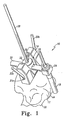
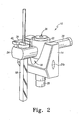
- FIGS. 1 and 2 show a cutting guide 10 which allows for the cutting of a humeral head 12.
- the cutting guide 10 is used to remove a portion of the humeral head 12 to allow for the placement of an implant (not shown).
- the cutting guide 10 includes a housing 14.
- the housing 14 includes a three-dimensional guide path, such as a slanted parabolic slot 16 for coupling to a burr 18.
- the slot 16 extends longitudinally and laterally.
- the slot 16 defines the path that the burr 18 will cut.
- the multi-directional nature of the slot 16 enables the burr 18 to move both in the proximal/distal plane and also the medial/lateral plane, thereby allowing for a multiplanar cut.
- An arm 20 extends through the slot 16 and includes a burr-attachment end and a quick-connect end.
- the burr-attachment end is coupled to the burr 18.
- the arm 20 is held in place in the slot 16 by an adjustable cylinder 22.
- the arm 20 includes a burr restraint portion 24 that is used to hold the burr 18 on its path.
- the adjustable cylinder 22 allows the surgeon to adjust the distance between the burr 18 and the housing 14, which will be described in more detail in reference to FIG. 3 below.
- the quick-connect end 20b of the arm 20 allows the surgeon to hold the burr with one hand while holding a drill portion with the other hand.
- the adjustable cylinder 22 includes an opening 26 that extends longitudinally through the adjustable cylinder 22.
- the opening 26 is adapted to receive a guide pin 28.
- the guide pin 28 extends through opening 26 and a post 29 of the housing 14 into a humerus 30 for holding the cutting guide 10 in place relative to the humeral head 12.
- the housing 14 also includes a pair of pin holes 31a, 31b on the sides to align the housing anteriorly and posteriorly on the humeral head 12. Pins 32a, 32b fit through the pin holes 31a, 31b to further affix the housing 14 to the humeral head 12. The pins 32a, 32b prevent the cutting guide 10 from sliding around on the humeral head 12.
- FIG. 3 a perspective view of the arm 20 is shown.
- An elongated slot 33 extends through the arm 20.
- the elongated slot 33 is dimensioned so as to receive the guide pin 28.
- the arm 20 also includes a plurality of notches 34 that are adapted to correspond with an adjustable pin (not shown).
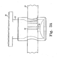
- the notches 34 extend around the arm 20 and engage a movable ridge 36 on the inside of the adjustable cylinder 22 ( FIG. 3A ).
- the ridge 36 couples with one of the notches 34, locking the arm 20 in a particular location relative to the housing 14.
- a button 38 is included on the top of the adjustable cylinder 22. As best shown in FIG.
- the arm 20 may include markings to aid the surgeon in measuring the distance between the cylinder 22 and the burr 18, which will adjust the radius of the cut area.
- the cylinder 22 may include a notch and the arm 20 may include ridges.
- other known releasable locking mechanisms may be used.
- the restraint portion 24 includes a positioning member 39.
- the positioning member 39 allows the user to adjust the burr 18 up or down. By being able to adjust the vertical location of the burr 18, the user can control the depth that the burr 18 will cut.
- the vertically adjustable piece 39 includes a screw 40 that can be adjusted to different heights, allowing the burr 18 to be adjusted.
- the burr 18 may not be vertically adjustable. Instead, there may be provided a plurality of burrs that have different depths, which would allow for different heights to be cut.
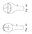
- FIGS. 4A and 4B show a top and a side view of the humerus 30.
- the humerus 30 includes a greater humeral tubercle 44 (best seen in FIG. 1 ) that needs to be either partially or wholly removed.
- the greater humeral tubercle 44 includes a radius R and a depth D.
- the cutting guide 10 of the present invention will be able to cut both the radius R and the depth D in a single step, as will be described below.
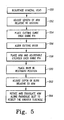
- a humeral head 12 is resurfaced using a spherical reamer over the guide pin 28.
- the reamer allows for a flat surface to be created on the top of the humeral head 12.
- the length of the arm 20 is adjusted to the desired length.
- the cutting guide 10 is placed over the guide pin 28.
- the housing 14 of the cutting guide 10 sits on the flat on the top of the humeral head 12.
- the post 29 fits into the reamed hole.
- the cutting guide 10 is aligned using the pin holes 31a, 31b on the housing 14.
- Pins 32a, 32b are placed in the pin holes 31a, 31b at step s56 to prevent rotation of the housing 14.
- the arm 20 and adjustable cylinder 22 are then placed over the guide pin 28 in the parabolic slot 16 of the housing 20.
- the burr 18 is then placed into the restraint portion 24 of the arm 20 at step s60.
- the depth of the burr 18 will be adjusted (if so desired).
- the arm 20 is then rotated and translated along the parabolic slot 16 to resect the radius R and depth D simultaneously on the humerus 30 at step s64.
- the cutting guide 10 is then removed from the guide pin 28 and the trialing and implantation of the prosthesis can occur.
- step s52 may take place after the arm 20 is placed over the guide pin 28.
- step 62 may not be included.
- multiple burrs of different sizes may be included and the surgeon selects one of the burrs depending on the depth the surgeon would like to cut.
- both the arm 20 and the burr are adjustable relative to the housing 14, both the radius and the depth to be cut can be adjusted depending upon the anatomy of the patient or the need of the surgeon.
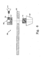
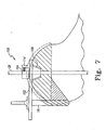
- a cutting guide 100 is provided that includes an arm 102 that couples to the burr 18.
- the cutting guide 100 further includes a housing 104.
- the housing 104 includes an opening 106 to enable the housing 104 to slide over the guide pin 28.
- the cutting guide 100 also includes a stem hole stabilizer 108 that attaches to the housing 104 via a threaded portion 110 as shown in FIG. 6 .
- the threaded portion 110 engages a threaded opening 112 in the housing 104.
- the housing 104 and stem hole stabilizer 108 can be adjusted vertically relative to the guide pin 28 via a screw 114 that locks the housing in position on the guide pin 28.
- the arm 102 swings along a curved path on the humeral head 12, guiding the burr 18.
- the swinging of the arm 102 causes the burr 18 to cut off a radius of the greater tubercle.
- the burr 18 swings along an arcuate path on the greater tubercle.
- Another cutting guide would need to be used to cut the appropriate depth.
- the burr 18 is made of a stainless steel having a hardness between about 40 and 55 on the Rockwell scale. Where the burr 18 is only intended to be used once, the burr may be made of a softer metal. The burr 18 may be made of a softer metal, but may be coated with stainless steel having the hardness described above.
- the arm 20 may be made of stainless steel or other sterilisable metals. The arm 20 itself may also be a one-time instrument made of a polymer material.
- the housing 14 may also be made of stainless steel or other sterilisable metal. The housing may also be made of a polymer material. In the above-described cutting guide, the path cut was an arcuate path that included both a radius and a depth.
- the multi-dimensional guide path could be designed so as to cut other dimensions that result in two planes being simultaneously cut.
- the path may be a parabolic slot that cuts both a radius and a width.
- the path may be of a different shape that cuts an oval or a rectangle while simultaneously cutting another dimension.
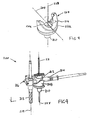
- FIG. 9 shows another embodiment of a bone cutting assembly 200 for guiding a burr cutting tool 218 which has an axis of rotation 219.
- the bone cutting assembly 200 includes a housing 208, which rotatably receives a mounting cylinder 212 having a through bore in which a burr mounting arm 214 can be received.
- the bone cutting assembly 200 may further include a clamp 216 on one end of burr mounting arm 214 for engaging burr cutting tool 218, for example as described above with reference to FIG. 2 .
- the bone cutting assembly 200 also includes a guide pin 28 defining a cutting axis 228, about which burr cutting tool 218, mounting cylinder 212 and arm 214 may pivot when the distal end of guide pin 28 is securely positioned into the bone such as the proximal humerus.
- the burr mounting arm 214 may be fixed against sliding relative to the mounting cylinder 212 as described above with reference to FIG. 3A .
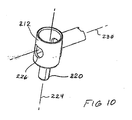
- FIG. 8 and FIG. 10 are detailed views, respectively, of the housing 208 and the mounting cylinder 212.
- the housing 208 has a bore 202 sized for slidably and rotatably receiving a boss 220 on the mounting cylinder 212 ( FIG. 10 ).
- the boss 220 has an internal bore (not visible) along axis 224 for passage of guide pin 28.
- a transverse through-hole 226 extending through the mounting cylinder 212 can receive the mounting arm 214 along an arm axis 230.
- the housing 208 defines a slot along an axis 204 which is perpendicular to the bore 202.
- the slot is defined at one end by a cam surface 206 which is generally concave, for example having a parabolic shape when viewed generally along the axis 204.
- An edge wall 222 is the portion of the housing 208 that borders the cam surface 206. When viewed from above in the direction of axis 228, the edge wall 222 may have the shape of a portion of a circle.
- the bone cutting assembly 200 may be used to mill a portion of a bone such as the proximal humerus, for example, in order to seat a humeral prosthesis as previously described.
- the milled portion of bone generally defines a portion of a cylinder having a radius determined by the adjustment of mounting arm 214 relative to cutting axis 228.
- the profile and depth of the distal edge of the removed bone, as created by the distal tip of burr cutting tool 218 as it swings about cutting axis 228, is determined by the shape of cam surface 206. This is achieved by swinging the burr mounting arm 214, while the rotating burr cutting tool 218 is retained within the clamp 216 at one end of the arm 214, around the cutting axis 228.
- the arm 214 follows the cam surface 206.
- the surgeon may grip a control handle (not shown) attached to the end of the arm 214 opposite to the cutting tool 218 to control the movement of the arm.
- the burr mounting arm 20,214 acts directly against the cam surface 206.
- the housing 14,208 includes a slot 16 defined by the cam surface and extending transverse to the cutting axis 228, and in which the burr mounting arm fits within the slot.
- the burr mounting arm can be rotated about the cutting axis through an angle of at least 10°.
- the burr mounting arm can be rotated about the cutting axis through an angle of not more than about 180°.
- the assembly includes a burr cutting tool 18,218 retained on the burr mounting arm.
- the burr cutting tool has an axis of rotation 219 that is approximately parallel to the cutting axis 228 defined by the guide pin 28.
- the assembly includes a mounting cylinder 22, 212 that fits on to the guide pin and that includes a through bore 26,226 extending transversely relative to the cutting axis, and in which the burr mounting arm can be received in the through bore.
- the spacing of one end of the burr mounting arm relative to the mounting cylinder can be adjusted.
- the cam surface when viewed in the direction of the cutting axis, is shaped like a portion of a circle.
- the cam surface has a generally concave profile when viewed in a direction transverse to the cutting axis.
Landscapes
- Health & Medical Sciences (AREA)
- Surgery (AREA)
- Life Sciences & Earth Sciences (AREA)
- Biomedical Technology (AREA)
- Medical Informatics (AREA)
- Orthopedic Medicine & Surgery (AREA)
- Oral & Maxillofacial Surgery (AREA)
- Engineering & Computer Science (AREA)
- Dentistry (AREA)
- Heart & Thoracic Surgery (AREA)
- Nuclear Medicine, Radiotherapy & Molecular Imaging (AREA)
- Molecular Biology (AREA)
- Animal Behavior & Ethology (AREA)
- General Health & Medical Sciences (AREA)
- Public Health (AREA)
- Veterinary Medicine (AREA)
- Surgical Instruments (AREA)
- Prostheses (AREA)
Claims (10)
- Schnittführung (10, 200) zur Entfernung von Knochen während einer Gelenkersatzoperation, umfassend:ein Gehäuse (14, 208), das einen darin ausgebildeten Schlitz (16, 264) aufweist, wobei der Schlitz eine Führungsbahn definiert, die sich in drei Dimensionen erstreckt, undeinen Arm (20, 214), der mit dem Gehäuse gekoppelt ist und einen Bohrer (18, 218) enthält, der von dem Gehäuse geführt wird, um simultan in zwei Ebenen zu schneiden, wenn der Arm entlang der Führungsbahn geschoben wird,dadurch gekennzeichnet, dass der in dem Gehäuse ausgebildete Schlitz an einem Ende eine Kurvenfläche (206) definiert, die bei Betrachtung entlang der Achse (204) des Schlitzes konkav ist, und sich der Arm durch den Schlitz in dem Gehäuse so erstreckt, dass der Bohrer simultan in zwei Ebenen schneiden kann, wenn der Arm entlang der Führungsbahn durch Bewegen des Arms in dem Schlitz entlang der Kurvenfläche geschoben wird.
- Schnittführung nach Anspruch 1, wobei die dreidimensionale Führungsbahn ein schräger parabolischer Schlitz (16) ist.
- Schnittführung nach Anspruch 1, wobei der Arm (20, 214) ferner einen Halteabschnitt (24, 216) zum Koppeln des Bohrers (18, 218) mit dem Arm enthält.
- Schnittführung nach Anspruch 3, wobei der Halteabschnitt (24, 216) ein vertikal einstellbares Stück (39) zum Einstellen der Tiefe des Bohrers (18, 218) relativ zum Arm (20, 214) enthält.
- Schnittführung nach Anspruch 1, wobei der Arm (20, 214) mit dem Gehäuse (14, 208) beweglich gekoppelt ist.
- Schnittführung nach Anspruch 5, wobei ein einstellbarer Zylinder (22, 212) den Arm (20, 214) mit dem Gehäuse (14, 268) beweglich koppelt, wobei der einstellbare Zylinder einen Sicherungsmechanismus (34, 36) zur lösbaren Sicherung des einstellbaren Zylinders an dem Arm enthält.
- Schnittführung nach Anspruch 6, wobei der Sicherungsmechanismus eine Vielzahl von Kerben (34) an dem Arm (20, 214) oder dem einstellbaren Zylinder (22, 212) und eine bewegliche Erhebung (36) für einen Eingriff mit einer der Vielzahl von Kerben auf dem Anderen von dem Arm und dem einstellbaren Zylinder enthält.
- Schnittführung nach Anspruch 6, wobei der Sicherungsmechanismus durch Drücken eines Knopfes (38) aktiviert wird.
- Schnittführung nach Anspruch 1, wobei der Arm (20, 214) so einstellbar ist, dass der zu schneidende Radius geändert werden kann.
- Schnittführung nach Anspruch 1, ferner umfassend eine Vielzahl von Bohrern, wobei jeder der Vielzahl von Bohrern gestaltet ist, um eine andere Tiefe zu schneiden.
Applications Claiming Priority (2)
| Application Number | Priority Date | Filing Date | Title |
|---|---|---|---|
| US12/062,952 US8114087B2 (en) | 2008-04-04 | 2008-04-04 | Humeral rotating burr guide |
| EP09157237A EP2106756B1 (de) | 2008-04-04 | 2009-04-02 | Knochenschneideanordnung |
Related Parent Applications (1)
| Application Number | Title | Priority Date | Filing Date |
|---|---|---|---|
| EP09157237.0 Division | 2009-04-02 |
Publications (2)
| Publication Number | Publication Date |
|---|---|
| EP2206468A1 EP2206468A1 (de) | 2010-07-14 |
| EP2206468B1 true EP2206468B1 (de) | 2011-12-07 |
Family
ID=40863688
Family Applications (3)
| Application Number | Title | Priority Date | Filing Date |
|---|---|---|---|
| EP09157237A Active EP2106756B1 (de) | 2008-04-04 | 2009-04-02 | Knochenschneideanordnung |
| EP10170055A Withdrawn EP2308396A1 (de) | 2008-04-04 | 2009-04-02 | Knochenschneideanordnung |
| EP10156133A Active EP2206468B1 (de) | 2008-04-04 | 2009-04-02 | Knochenschneideanordnung |
Family Applications Before (2)
| Application Number | Title | Priority Date | Filing Date |
|---|---|---|---|
| EP09157237A Active EP2106756B1 (de) | 2008-04-04 | 2009-04-02 | Knochenschneideanordnung |
| EP10170055A Withdrawn EP2308396A1 (de) | 2008-04-04 | 2009-04-02 | Knochenschneideanordnung |
Country Status (4)
| Country | Link |
|---|---|
| US (4) | US8114087B2 (de) |
| EP (3) | EP2106756B1 (de) |
| AT (2) | ATE536143T1 (de) |
| DE (1) | DE602009000114D1 (de) |
Families Citing this family (50)
| Publication number | Priority date | Publication date | Assignee | Title |
|---|---|---|---|---|
| US7896883B2 (en) | 2000-05-01 | 2011-03-01 | Arthrosurface, Inc. | Bone resurfacing system and method |
| US8177841B2 (en) | 2000-05-01 | 2012-05-15 | Arthrosurface Inc. | System and method for joint resurface repair |
| US7163541B2 (en) | 2002-12-03 | 2007-01-16 | Arthrosurface Incorporated | Tibial resurfacing system |
| US6520964B2 (en) | 2000-05-01 | 2003-02-18 | Std Manufacturing, Inc. | System and method for joint resurface repair |
| US8361159B2 (en) | 2002-12-03 | 2013-01-29 | Arthrosurface, Inc. | System for articular surface replacement |
| US6610067B2 (en) | 2000-05-01 | 2003-08-26 | Arthrosurface, Incorporated | System and method for joint resurface repair |
| US7678151B2 (en) * | 2000-05-01 | 2010-03-16 | Ek Steven W | System and method for joint resurface repair |
| US7901408B2 (en) | 2002-12-03 | 2011-03-08 | Arthrosurface, Inc. | System and method for retrograde procedure |
| US7914545B2 (en) | 2002-12-03 | 2011-03-29 | Arthrosurface, Inc | System and method for retrograde procedure |
| US8388624B2 (en) * | 2003-02-24 | 2013-03-05 | Arthrosurface Incorporated | Trochlear resurfacing system and method |
| CA2546582A1 (en) | 2003-11-20 | 2005-06-09 | Arthrosurface, Inc. | Retrograde delivery of resurfacing devices |
| US7828853B2 (en) | 2004-11-22 | 2010-11-09 | Arthrosurface, Inc. | Articular surface implant and delivery system |
| US9358029B2 (en) | 2006-12-11 | 2016-06-07 | Arthrosurface Incorporated | Retrograde resection apparatus and method |
| FR2932674B1 (fr) | 2008-06-20 | 2011-11-18 | Tornier Sa | Procede de modelisation d'une surface glenoidienne d'une omoplate, dispositif d'implantation d'un composant glenoidien d'une prothese d'epaule, et procede de fabrication d'un tel compose. |
| CA2759027C (en) | 2009-04-17 | 2020-02-25 | Arthrosurface Incorporated | Glenoid resurfacing system and method |
| WO2010121250A1 (en) | 2009-04-17 | 2010-10-21 | Arthrosurface Incorporated | Glenoid resurfacing system and method |
| US10945743B2 (en) | 2009-04-17 | 2021-03-16 | Arthrosurface Incorporated | Glenoid repair system and methods of use thereof |
| EP2542165A4 (de) * | 2010-03-05 | 2015-10-07 | Arthrosurface Inc | Schienbein-oberflächenersatzsystem und -verfahren |
| US9066716B2 (en) | 2011-03-30 | 2015-06-30 | Arthrosurface Incorporated | Suture coil and suture sheath for tissue repair |
| EP2804565B1 (de) | 2011-12-22 | 2018-03-07 | Arthrosurface Incorporated | System zur knochenfixierung |
| WO2013148229A1 (en) | 2012-03-30 | 2013-10-03 | Depuy Products, Inc. | Stemless humeral component and associated surgical instruments and methods |
| DE112013003358T5 (de) | 2012-07-03 | 2015-03-19 | Arthrosurface, Inc. | System und Verfahren für Gelenkoberflächenersatz und -reparatur |
| US9629646B2 (en) | 2012-07-11 | 2017-04-25 | Jens Kather | Curved burr surgical instrument |
| US9295488B2 (en) * | 2012-08-09 | 2016-03-29 | Wilson T. Asfora | Joint fusion |
| FR2997285B1 (fr) * | 2012-10-26 | 2014-12-26 | Aston Medical | Gabarit de pose d'un 'implant d'articulation d'une prothese d'epaule sur une tete humerale |
| US9492200B2 (en) | 2013-04-16 | 2016-11-15 | Arthrosurface Incorporated | Suture system and method |
| US11607319B2 (en) | 2014-03-07 | 2023-03-21 | Arthrosurface Incorporated | System and method for repairing articular surfaces |
| US9861492B2 (en) | 2014-03-07 | 2018-01-09 | Arthrosurface Incorporated | Anchor for an implant assembly |
| US10624748B2 (en) | 2014-03-07 | 2020-04-21 | Arthrosurface Incorporated | System and method for repairing articular surfaces |
| US10568647B2 (en) | 2015-06-25 | 2020-02-25 | Biomet Manufacturing, Llc | Patient-specific humeral guide designs |
| US10226262B2 (en) * | 2015-06-25 | 2019-03-12 | Biomet Manufacturing, Llc | Patient-specific humeral guide designs |
| US10357255B2 (en) | 2015-10-08 | 2019-07-23 | Howmedica Osteonics Corp. | Globalized total knee instrumentation |
| TWI566173B (zh) * | 2015-12-29 | 2017-01-11 | 瑞軒科技股份有限公司 | 音訊播放裝置及方法 |
| EP3685804A1 (de) | 2016-03-25 | 2020-07-29 | Tornier | Gelenkprothesenabstandhalter |
| US11166733B2 (en) | 2017-07-11 | 2021-11-09 | Howmedica Osteonics Corp. | Guides and instruments for improving accuracy of glenoid implant placement |
| WO2019014281A1 (en) * | 2017-07-11 | 2019-01-17 | Tornier, Inc. | HUMERAL CUTTING GUIDES SPECIFIC TO A PATIENT |
| CA3108761A1 (en) | 2017-08-04 | 2019-02-07 | Arthrosurface Incorporated | Multicomponent articular surface implant |
| CA3087066A1 (en) | 2017-12-29 | 2019-07-04 | Tornier, Inc. | Patient specific humeral implant components |
| GB2609338B (en) | 2019-03-12 | 2023-06-14 | Arthrosurface Inc | Humeral and glenoid articular surface implant systems and methods |
| US11986251B2 (en) | 2019-09-13 | 2024-05-21 | Treace Medical Concepts, Inc. | Patient-specific osteotomy instrumentation |
| IT201900024069A1 (it) * | 2019-12-16 | 2021-06-16 | Limacorporate Spa | Dispositivo di posizionamento glenoideo |
| CN113057712B (zh) * | 2021-02-25 | 2022-03-11 | 北京市春立正达医疗器械股份有限公司 | 一种胫骨截骨导向器 |
| US12121244B2 (en) | 2021-09-13 | 2024-10-22 | Arthrex, Inc. | Guide apparatus for surgical cutting tool |
| US12702484B2 (en) | 2022-03-31 | 2026-08-11 | Treace Medical Concepts, Inc. | Apparatus, system, and method for generating patient-specific implants and/or instrumentation |
| US12661133B2 (en) | 2022-05-12 | 2026-06-23 | Treace Medical Concepts, Inc. | Apparatus, system, and method for patient-specific methods and instrumentation |
| CN114916988B (zh) * | 2022-06-13 | 2024-12-24 | 北京大学第三医院(北京大学第三临床医学院) | 一种骨切割机构 |
| EP4539753A1 (de) | 2022-06-17 | 2025-04-23 | Treace Medical Concepts, Inc. | Vorrichtung, system und verfahren zur erzeugung patientenspezifischer implantate und/oder instrumente für osteotomien |
| US12484973B2 (en) * | 2022-07-21 | 2025-12-02 | Intellijoint Surgical Inc. | Method and apparatus for resecting bone using a planer and optionally using a robot to assist with placement and/or installation of guide pins |
| US20240148470A1 (en) * | 2022-11-03 | 2024-05-09 | Hunter Chase Fleenor | Parallel and angled dental implant placement guide |
| JP2026505040A (ja) | 2023-01-28 | 2026-02-10 | トリース メディカル コンセプツ,インコーポレイティド | 骨切り術のための装置、システム、及び方法 |
Family Cites Families (25)
| Publication number | Priority date | Publication date | Assignee | Title |
|---|---|---|---|---|
| GB8908685D0 (en) * | 1989-04-18 | 1989-06-07 | Neoligaments Ltd | Instrument for use in knee surgery |
| US5961555A (en) * | 1998-03-17 | 1999-10-05 | Huebner; Randall J. | Modular shoulder prosthesis |
| FR2721202B1 (fr) | 1994-06-16 | 1996-10-04 | Patrick Marie Crol Labourdette | Prothèse fémoro-patellaire et dispositif ancillaire pour former une empreinte trochléenne de réception de cette prothèse. |
| FR2731897B1 (fr) | 1995-03-22 | 1997-09-26 | Cedior | Dispositif de coupe tibiale pour la pose d'une prothese totale de genou |
| US6379391B1 (en) * | 1999-09-15 | 2002-04-30 | Medidea, Llc | Method and apparatus for positioning a prosthetic element relative to a bone to achieve a desired orientation |
| US5779710A (en) * | 1996-06-21 | 1998-07-14 | Matsen, Iii; Frederick A. | Joint replacement method and apparatus |
| US5779709A (en) * | 1997-02-12 | 1998-07-14 | Wright Medical Technology, Inc. | Ulnar cut guide alignment system |
| GB9707853D0 (en) * | 1997-04-18 | 1997-06-04 | Headcorn Instrumentation Ltd | Prosthesis |
| DE19802751A1 (de) | 1997-07-21 | 1999-01-28 | Sandhaus Sami Prof Dr Med Dr H | Führungsvorrichtung für Instrumente, insbesondere für kieferorthopädische und zahnmedizinische Instrumente |
| FR2773469B1 (fr) * | 1998-01-09 | 2000-03-03 | Alain Leonard | Equipement chirurgical pour l'implantation d'une prothese totale d'epaule, et prothese totale d'epaule constitutive |
| US6494913B1 (en) * | 1998-03-17 | 2002-12-17 | Acumed, Inc. | Shoulder prosthesis |
| WO2001082843A2 (en) * | 2000-05-03 | 2001-11-08 | Smith & Nephew, Inc. | Multi modular trialing system and instrumentation |
| US20020016634A1 (en) * | 2000-07-28 | 2002-02-07 | Brian Maroney | Device and method for positioning an eccentric humeral head of a humerus prothesis for a shoulder arthroplasty |
| US6620197B2 (en) * | 2001-01-23 | 2003-09-16 | Depuy Orthopaedics, Inc. | Method and apparatus for performing a shoulder replacement procedure in the treatment of cuff tear arthropathy |
| US6780190B2 (en) * | 2001-01-23 | 2004-08-24 | Depuy Orthopaedics, Inc. | Method and apparatus for resecting a greater tubercle from a humerus of a patient during performance of a shoulder replacement procedure |
| US6530957B1 (en) * | 2001-08-23 | 2003-03-11 | Howmedica Osteonics Corp. | Modular joint prosthesis with multiple offset humeral head component and method |
| US7097663B1 (en) * | 2001-12-17 | 2006-08-29 | Smith & Nephew, Inc. | Modular prosthesis system with novel locking mechanism |
| US7166133B2 (en) * | 2002-06-13 | 2007-01-23 | Kensey Nash Corporation | Devices and methods for treating defects in the tissue of a living being |
| US7083625B2 (en) * | 2002-06-28 | 2006-08-01 | Sdgi Holdings, Inc. | Instruments and techniques for spinal disc space preparation |
| DE10309987B4 (de) | 2003-02-28 | 2005-09-01 | Aesculap Ag & Co. Kg | Chirurgische Positionier- und Haltevorrichtung |
| US7517364B2 (en) * | 2003-03-31 | 2009-04-14 | Depuy Products, Inc. | Extended articulation orthopaedic implant and associated method |
| US20050043805A1 (en) * | 2003-08-11 | 2005-02-24 | Chudik Steven C. | Devices and methods used for shoulder replacement |
| US7338496B1 (en) * | 2003-08-29 | 2008-03-04 | Biomet Manufacturing Corp. | Method and apparatus for positioning an implant |
| US7585327B2 (en) * | 2003-09-24 | 2009-09-08 | Biomet Manufacturing Corp. | Extended articular surface resurfacing head |
| FR2863859B1 (fr) | 2003-12-23 | 2006-02-03 | Ct Pulse France Sa | Ancillaire destine a la mise en place d'une prothese de resurfacage d'une tete femorale. |
-
2008
- 2008-04-04 US US12/062,952 patent/US8114087B2/en active Active
-
2009
- 2009-04-02 EP EP09157237A patent/EP2106756B1/de active Active
- 2009-04-02 AT AT10156133T patent/ATE536143T1/de active
- 2009-04-02 DE DE602009000114T patent/DE602009000114D1/de active Active
- 2009-04-02 US US12/417,212 patent/US8231630B2/en active Active
- 2009-04-02 AT AT09157237T patent/ATE477753T1/de not_active IP Right Cessation
- 2009-04-02 EP EP10170055A patent/EP2308396A1/de not_active Withdrawn
- 2009-04-02 EP EP10156133A patent/EP2206468B1/de active Active
-
2012
- 2012-01-12 US US13/348,902 patent/US8657828B2/en not_active Expired - Fee Related
-
2013
- 2013-10-02 US US14/044,374 patent/US8845643B2/en active Active
Also Published As
| Publication number | Publication date |
|---|---|
| US20090264889A1 (en) | 2009-10-22 |
| US20120116405A1 (en) | 2012-05-10 |
| ATE536143T1 (de) | 2011-12-15 |
| US8845643B2 (en) | 2014-09-30 |
| DE602009000114D1 (de) | 2010-09-30 |
| US8231630B2 (en) | 2012-07-31 |
| EP2206468A1 (de) | 2010-07-14 |
| US8114087B2 (en) | 2012-02-14 |
| US20090254091A1 (en) | 2009-10-08 |
| US8657828B2 (en) | 2014-02-25 |
| EP2106756B1 (de) | 2010-08-18 |
| ATE477753T1 (de) | 2010-09-15 |
| US20140074095A1 (en) | 2014-03-13 |
| EP2106756A1 (de) | 2009-10-07 |
| EP2308396A1 (de) | 2011-04-13 |
Similar Documents
| Publication | Publication Date | Title |
|---|---|---|
| EP2106756B1 (de) | Knochenschneideanordnung | |
| US8523869B2 (en) | Patello-femoral joint implant and instrumentation | |
| US8123758B2 (en) | Femoral guide for implanting a femoral knee prosthesis | |
| AU2007200979B2 (en) | Compound offset handle | |
| US6712823B2 (en) | Humeral head resection guide | |
| AU676697B2 (en) | Orthopaedic cutting instrument and prosthetic device | |
| EP0460886B1 (de) | Führung mit intramedullärer Referenz, zur Resektion des Oberarmknochenkopfes | |
| EP1374783B1 (de) | Führungsvorrichtung zum Schneiden einer Aussparung für eine Gelenkprothese und zugehöriges Schneidwerkzeug | |
| WO1994009730A9 (en) | Orthopaedic cutting instrument and prosthetic device | |
| WO1998035620A1 (en) | Ulnar cut guide alignment system | |
| WO2014006360A1 (en) | A measuring instrument for use in orthopaedic surgery | |
| AU2011239283B2 (en) | Compound offset handle | |
| EP1836975B1 (de) | Chirurgisches Instrument zur Lokalisierung einer Schnittebene auf einem Knochen | |
| AU2012261710A1 (en) | Patello-femoral joint implant and instrumentation |
Legal Events
| Date | Code | Title | Description |
|---|---|---|---|
| PUAI | Public reference made under article 153(3) epc to a published international application that has entered the european phase |
Free format text: ORIGINAL CODE: 0009012 |
|
| 17P | Request for examination filed |
Effective date: 20100310 |
|
| AC | Divisional application: reference to earlier application |
Ref document number: 2106756 Country of ref document: EP Kind code of ref document: P |
|
| AK | Designated contracting states |
Kind code of ref document: A1 Designated state(s): AT BE BG CH CY CZ DE DK EE ES FI FR GB GR HR HU IE IS IT LI LT LU LV MC MK MT NL NO PL PT RO SE SI SK TR |
|
| AX | Request for extension of the european patent |
Extension state: AL BA RS |
|
| 17Q | First examination report despatched |
Effective date: 20101217 |
|
| GRAP | Despatch of communication of intention to grant a patent |
Free format text: ORIGINAL CODE: EPIDOSNIGR1 |
|
| RIC1 | Information provided on ipc code assigned before grant |
Ipc: A61B 17/15 20060101ALN20110628BHEP Ipc: A61B 17/17 20060101AFI20110628BHEP |
|
| GRAS | Grant fee paid |
Free format text: ORIGINAL CODE: EPIDOSNIGR3 |
|
| GRAA | (expected) grant |
Free format text: ORIGINAL CODE: 0009210 |
|
| AC | Divisional application: reference to earlier application |
Ref document number: 2106756 Country of ref document: EP Kind code of ref document: P |
|
| AK | Designated contracting states |
Kind code of ref document: B1 Designated state(s): AT BE BG CH CY CZ DE DK EE ES FI FR GB GR HR HU IE IS IT LI LT LU LV MC MK MT NL NO PL PT RO SE SI SK TR |
|
| REG | Reference to a national code |
Ref country code: GB Ref legal event code: FG4D |
|
| REG | Reference to a national code |
Ref country code: CH Ref legal event code: EP |
|
| REG | Reference to a national code |
Ref country code: IE Ref legal event code: FG4D |
|
| REG | Reference to a national code |
Ref country code: CH Ref legal event code: NV Representative=s name: E. BLUM & CO. AG PATENT- UND MARKENANWAELTE VSP |
|
| REG | Reference to a national code |
Ref country code: DE Ref legal event code: R096 Ref document number: 602009004106 Country of ref document: DE Effective date: 20120209 |
|
| REG | Reference to a national code |
Ref country code: NL Ref legal event code: VDEP Effective date: 20111207 |
|
| PG25 | Lapsed in a contracting state [announced via postgrant information from national office to epo] |
Ref country code: NO Free format text: LAPSE BECAUSE OF FAILURE TO SUBMIT A TRANSLATION OF THE DESCRIPTION OR TO PAY THE FEE WITHIN THE PRESCRIBED TIME-LIMIT Effective date: 20120307 Ref country code: LT Free format text: LAPSE BECAUSE OF FAILURE TO SUBMIT A TRANSLATION OF THE DESCRIPTION OR TO PAY THE FEE WITHIN THE PRESCRIBED TIME-LIMIT Effective date: 20111207 |
|
| LTIE | Lt: invalidation of european patent or patent extension |
Effective date: 20111207 |
|
| PG25 | Lapsed in a contracting state [announced via postgrant information from national office to epo] |
Ref country code: HR Free format text: LAPSE BECAUSE OF FAILURE TO SUBMIT A TRANSLATION OF THE DESCRIPTION OR TO PAY THE FEE WITHIN THE PRESCRIBED TIME-LIMIT Effective date: 20111207 Ref country code: LV Free format text: LAPSE BECAUSE OF FAILURE TO SUBMIT A TRANSLATION OF THE DESCRIPTION OR TO PAY THE FEE WITHIN THE PRESCRIBED TIME-LIMIT Effective date: 20111207 Ref country code: SE Free format text: LAPSE BECAUSE OF FAILURE TO SUBMIT A TRANSLATION OF THE DESCRIPTION OR TO PAY THE FEE WITHIN THE PRESCRIBED TIME-LIMIT Effective date: 20111207 Ref country code: SI Free format text: LAPSE BECAUSE OF FAILURE TO SUBMIT A TRANSLATION OF THE DESCRIPTION OR TO PAY THE FEE WITHIN THE PRESCRIBED TIME-LIMIT Effective date: 20111207 Ref country code: GR Free format text: LAPSE BECAUSE OF FAILURE TO SUBMIT A TRANSLATION OF THE DESCRIPTION OR TO PAY THE FEE WITHIN THE PRESCRIBED TIME-LIMIT Effective date: 20120308 Ref country code: NL Free format text: LAPSE BECAUSE OF FAILURE TO SUBMIT A TRANSLATION OF THE DESCRIPTION OR TO PAY THE FEE WITHIN THE PRESCRIBED TIME-LIMIT Effective date: 20111207 |
|
| PG25 | Lapsed in a contracting state [announced via postgrant information from national office to epo] |
Ref country code: CY Free format text: LAPSE BECAUSE OF FAILURE TO SUBMIT A TRANSLATION OF THE DESCRIPTION OR TO PAY THE FEE WITHIN THE PRESCRIBED TIME-LIMIT Effective date: 20111207 Ref country code: BE Free format text: LAPSE BECAUSE OF FAILURE TO SUBMIT A TRANSLATION OF THE DESCRIPTION OR TO PAY THE FEE WITHIN THE PRESCRIBED TIME-LIMIT Effective date: 20111207 |
|
| PG25 | Lapsed in a contracting state [announced via postgrant information from national office to epo] |
Ref country code: IS Free format text: LAPSE BECAUSE OF FAILURE TO SUBMIT A TRANSLATION OF THE DESCRIPTION OR TO PAY THE FEE WITHIN THE PRESCRIBED TIME-LIMIT Effective date: 20120407 Ref country code: SK Free format text: LAPSE BECAUSE OF FAILURE TO SUBMIT A TRANSLATION OF THE DESCRIPTION OR TO PAY THE FEE WITHIN THE PRESCRIBED TIME-LIMIT Effective date: 20111207 Ref country code: CZ Free format text: LAPSE BECAUSE OF FAILURE TO SUBMIT A TRANSLATION OF THE DESCRIPTION OR TO PAY THE FEE WITHIN THE PRESCRIBED TIME-LIMIT Effective date: 20111207 Ref country code: EE Free format text: LAPSE BECAUSE OF FAILURE TO SUBMIT A TRANSLATION OF THE DESCRIPTION OR TO PAY THE FEE WITHIN THE PRESCRIBED TIME-LIMIT Effective date: 20111207 Ref country code: BG Free format text: LAPSE BECAUSE OF FAILURE TO SUBMIT A TRANSLATION OF THE DESCRIPTION OR TO PAY THE FEE WITHIN THE PRESCRIBED TIME-LIMIT Effective date: 20120307 |
|
| PG25 | Lapsed in a contracting state [announced via postgrant information from national office to epo] |
Ref country code: PL Free format text: LAPSE BECAUSE OF FAILURE TO SUBMIT A TRANSLATION OF THE DESCRIPTION OR TO PAY THE FEE WITHIN THE PRESCRIBED TIME-LIMIT Effective date: 20111207 Ref country code: PT Free format text: LAPSE BECAUSE OF FAILURE TO SUBMIT A TRANSLATION OF THE DESCRIPTION OR TO PAY THE FEE WITHIN THE PRESCRIBED TIME-LIMIT Effective date: 20120409 Ref country code: RO Free format text: LAPSE BECAUSE OF FAILURE TO SUBMIT A TRANSLATION OF THE DESCRIPTION OR TO PAY THE FEE WITHIN THE PRESCRIBED TIME-LIMIT Effective date: 20111207 |
|
| REG | Reference to a national code |
Ref country code: AT Ref legal event code: MK05 Ref document number: 536143 Country of ref document: AT Kind code of ref document: T Effective date: 20111207 |
|
| PLBE | No opposition filed within time limit |
Free format text: ORIGINAL CODE: 0009261 |
|
| STAA | Information on the status of an ep patent application or granted ep patent |
Free format text: STATUS: NO OPPOSITION FILED WITHIN TIME LIMIT |
|
| PG25 | Lapsed in a contracting state [announced via postgrant information from national office to epo] |
Ref country code: DK Free format text: LAPSE BECAUSE OF FAILURE TO SUBMIT A TRANSLATION OF THE DESCRIPTION OR TO PAY THE FEE WITHIN THE PRESCRIBED TIME-LIMIT Effective date: 20111207 |
|
| 26N | No opposition filed |
Effective date: 20120910 |
|
| PG25 | Lapsed in a contracting state [announced via postgrant information from national office to epo] |
Ref country code: MC Free format text: LAPSE BECAUSE OF NON-PAYMENT OF DUE FEES Effective date: 20120430 Ref country code: IT Free format text: LAPSE BECAUSE OF FAILURE TO SUBMIT A TRANSLATION OF THE DESCRIPTION OR TO PAY THE FEE WITHIN THE PRESCRIBED TIME-LIMIT Effective date: 20111207 |
|
| REG | Reference to a national code |
Ref country code: DE Ref legal event code: R097 Ref document number: 602009004106 Country of ref document: DE Effective date: 20120910 |
|
| PG25 | Lapsed in a contracting state [announced via postgrant information from national office to epo] |
Ref country code: AT Free format text: LAPSE BECAUSE OF FAILURE TO SUBMIT A TRANSLATION OF THE DESCRIPTION OR TO PAY THE FEE WITHIN THE PRESCRIBED TIME-LIMIT Effective date: 20111207 |
|
| PG25 | Lapsed in a contracting state [announced via postgrant information from national office to epo] |
Ref country code: MK Free format text: LAPSE BECAUSE OF FAILURE TO SUBMIT A TRANSLATION OF THE DESCRIPTION OR TO PAY THE FEE WITHIN THE PRESCRIBED TIME-LIMIT Effective date: 20111207 |
|
| PG25 | Lapsed in a contracting state [announced via postgrant information from national office to epo] |
Ref country code: ES Free format text: LAPSE BECAUSE OF FAILURE TO SUBMIT A TRANSLATION OF THE DESCRIPTION OR TO PAY THE FEE WITHIN THE PRESCRIBED TIME-LIMIT Effective date: 20120318 |
|
| PG25 | Lapsed in a contracting state [announced via postgrant information from national office to epo] |
Ref country code: FI Free format text: LAPSE BECAUSE OF FAILURE TO SUBMIT A TRANSLATION OF THE DESCRIPTION OR TO PAY THE FEE WITHIN THE PRESCRIBED TIME-LIMIT Effective date: 20111207 |
|
| PG25 | Lapsed in a contracting state [announced via postgrant information from national office to epo] |
Ref country code: MT Free format text: LAPSE BECAUSE OF FAILURE TO SUBMIT A TRANSLATION OF THE DESCRIPTION OR TO PAY THE FEE WITHIN THE PRESCRIBED TIME-LIMIT Effective date: 20111207 |
|
| PG25 | Lapsed in a contracting state [announced via postgrant information from national office to epo] |
Ref country code: TR Free format text: LAPSE BECAUSE OF FAILURE TO SUBMIT A TRANSLATION OF THE DESCRIPTION OR TO PAY THE FEE WITHIN THE PRESCRIBED TIME-LIMIT Effective date: 20111207 |
|
| PG25 | Lapsed in a contracting state [announced via postgrant information from national office to epo] |
Ref country code: LU Free format text: LAPSE BECAUSE OF NON-PAYMENT OF DUE FEES Effective date: 20120402 |
|
| PG25 | Lapsed in a contracting state [announced via postgrant information from national office to epo] |
Ref country code: HU Free format text: LAPSE BECAUSE OF FAILURE TO SUBMIT A TRANSLATION OF THE DESCRIPTION OR TO PAY THE FEE WITHIN THE PRESCRIBED TIME-LIMIT Effective date: 20090402 |
|
| REG | Reference to a national code |
Ref country code: FR Ref legal event code: PLFP Year of fee payment: 8 |
|
| REG | Reference to a national code |
Ref country code: FR Ref legal event code: PLFP Year of fee payment: 9 |
|
| REG | Reference to a national code |
Ref country code: FR Ref legal event code: PLFP Year of fee payment: 10 |
|
| PGFP | Annual fee paid to national office [announced via postgrant information from national office to epo] |
Ref country code: IE Payment date: 20240312 Year of fee payment: 16 |
|
| PGFP | Annual fee paid to national office [announced via postgrant information from national office to epo] |
Ref country code: GB Payment date: 20240229 Year of fee payment: 16 |
|
| PGFP | Annual fee paid to national office [announced via postgrant information from national office to epo] |
Ref country code: FR Payment date: 20240311 Year of fee payment: 16 |
|
| PGFP | Annual fee paid to national office [announced via postgrant information from national office to epo] |
Ref country code: DE Payment date: 20240306 Year of fee payment: 16 |
|
| PGFP | Annual fee paid to national office [announced via postgrant information from national office to epo] |
Ref country code: CH Payment date: 20240501 Year of fee payment: 16 |
|
| REG | Reference to a national code |
Ref country code: DE Ref legal event code: R119 Ref document number: 602009004106 Country of ref document: DE |
|
| REG | Reference to a national code |
Ref country code: CH Ref legal event code: H13 Free format text: ST27 STATUS EVENT CODE: U-0-0-H10-H13 (AS PROVIDED BY THE NATIONAL OFFICE) Effective date: 20251125 |
|
| GBPC | Gb: european patent ceased through non-payment of renewal fee |
Effective date: 20250402 |
|
| PG25 | Lapsed in a contracting state [announced via postgrant information from national office to epo] |
Ref country code: DE Free format text: LAPSE BECAUSE OF NON-PAYMENT OF DUE FEES Effective date: 20251104 |
|
| PG25 | Lapsed in a contracting state [announced via postgrant information from national office to epo] |
Ref country code: GB Free format text: LAPSE BECAUSE OF NON-PAYMENT OF DUE FEES Effective date: 20250402 |
|
| PG25 | Lapsed in a contracting state [announced via postgrant information from national office to epo] |
Ref country code: FR Free format text: LAPSE BECAUSE OF NON-PAYMENT OF DUE FEES Effective date: 20250430 |
|
| PG25 | Lapsed in a contracting state [announced via postgrant information from national office to epo] |
Ref country code: CH Free format text: LAPSE BECAUSE OF NON-PAYMENT OF DUE FEES Effective date: 20250430 |
|
| PG25 | Lapsed in a contracting state [announced via postgrant information from national office to epo] |
Ref country code: IE Free format text: LAPSE BECAUSE OF NON-PAYMENT OF DUE FEES Effective date: 20250402 |