EP2206580A2 - Dispositif destiné au traitement de surfaces de sol - Google Patents
Dispositif destiné au traitement de surfaces de sol Download PDFInfo
- Publication number
- EP2206580A2 EP2206580A2 EP10150528A EP10150528A EP2206580A2 EP 2206580 A2 EP2206580 A2 EP 2206580A2 EP 10150528 A EP10150528 A EP 10150528A EP 10150528 A EP10150528 A EP 10150528A EP 2206580 A2 EP2206580 A2 EP 2206580A2
- Authority
- EP
- European Patent Office
- Prior art keywords
- brush
- fluid
- dispensing
- processing
- application
- Prior art date
- Legal status (The legal status is an assumption and is not a legal conclusion. Google has not performed a legal analysis and makes no representation as to the accuracy of the status listed.)
- Granted
Links
- 239000012530 fluid Substances 0.000 claims abstract description 70
- 238000000227 grinding Methods 0.000 claims abstract description 13
- 238000003754 machining Methods 0.000 claims abstract description 11
- 239000000428 dust Substances 0.000 claims description 7
- 238000003860 storage Methods 0.000 claims description 6
- 238000004140 cleaning Methods 0.000 claims description 4
- 238000005498 polishing Methods 0.000 claims description 4
- 239000004677 Nylon Substances 0.000 claims description 3
- 238000009826 distribution Methods 0.000 claims description 3
- 229920001778 nylon Polymers 0.000 claims description 3
- 238000009408 flooring Methods 0.000 claims description 2
- 239000003599 detergent Substances 0.000 claims 1
- 238000003892 spreading Methods 0.000 description 5
- 230000008901 benefit Effects 0.000 description 4
- 239000003921 oil Substances 0.000 description 3
- 239000012459 cleaning agent Substances 0.000 description 2
- 239000007787 solid Substances 0.000 description 2
- 239000007921 spray Substances 0.000 description 2
- 239000002023 wood Substances 0.000 description 2
- 208000027418 Wounds and injury Diseases 0.000 description 1
- 230000002745 absorbent Effects 0.000 description 1
- 239000002250 absorbent Substances 0.000 description 1
- 230000035508 accumulation Effects 0.000 description 1
- 238000009825 accumulation Methods 0.000 description 1
- 230000006978 adaptation Effects 0.000 description 1
- 230000009286 beneficial effect Effects 0.000 description 1
- 239000011248 coating agent Substances 0.000 description 1
- 238000000576 coating method Methods 0.000 description 1
- 239000012141 concentrate Substances 0.000 description 1
- 238000010276 construction Methods 0.000 description 1
- 238000011109 contamination Methods 0.000 description 1
- 230000006378 damage Effects 0.000 description 1
- 239000004744 fabric Substances 0.000 description 1
- 239000006260 foam Substances 0.000 description 1
- 208000014674 injury Diseases 0.000 description 1
- 239000000463 material Substances 0.000 description 1
- HBMJWWWQQXIZIP-UHFFFAOYSA-N silicon carbide Chemical compound [Si+]#[C-] HBMJWWWQQXIZIP-UHFFFAOYSA-N 0.000 description 1
- 229910010271 silicon carbide Inorganic materials 0.000 description 1
- 239000002689 soil Substances 0.000 description 1
- 238000005507 spraying Methods 0.000 description 1
Images

Classifications
-
- B—PERFORMING OPERATIONS; TRANSPORTING
- B24—GRINDING; POLISHING
- B24B—MACHINES, DEVICES, OR PROCESSES FOR GRINDING OR POLISHING; DRESSING OR CONDITIONING OF ABRADING SURFACES; FEEDING OF GRINDING, POLISHING, OR LAPPING AGENTS
- B24B7/00—Machines or devices designed for grinding plane surfaces on work, including polishing plane glass surfaces; Accessories therefor
- B24B7/10—Single-purpose machines or devices
- B24B7/18—Single-purpose machines or devices for grinding floorings, walls, ceilings or the like
- B24B7/188—Single-purpose machines or devices for grinding floorings, walls, ceilings or the like with cylinder- or belt-type tools
-
- B—PERFORMING OPERATIONS; TRANSPORTING
- B24—GRINDING; POLISHING
- B24B—MACHINES, DEVICES, OR PROCESSES FOR GRINDING OR POLISHING; DRESSING OR CONDITIONING OF ABRADING SURFACES; FEEDING OF GRINDING, POLISHING, OR LAPPING AGENTS
- B24B29/00—Machines or devices for polishing surfaces on work by means of tools made of soft or flexible material with or without the application of solid or liquid polishing agents
- B24B29/005—Machines or devices for polishing surfaces on work by means of tools made of soft or flexible material with or without the application of solid or liquid polishing agents using brushes
Definitions
- the invention relates to a device for processing of floor surfaces, in particular for grinding ground surfaces.
- a floor sander known with wheels and a carriage-like chassis.
- a drive motor mounted on the chassis drives a sanding belt running over two rollers to abrade a floor surface.
- wooden floor can be sanded.
- the invention has for its object to provide an aforementioned device, can be avoided with the problems of the prior art and in particular a comfortable for an operator editing a floor surface is possible.
- the device has a rotating processing device for the bottom surface, wherein said at least one brush, advantageously exactly one brush, has for soil cultivation.
- the device has a drive and a bearing for the processing device or the brush.
- the processing device for a good handling, it is designed in the manner of a car, so it has at least one wheel, preferably at least two.
- the processing device on the one hand, has a grinding brush for the abrading processing of the bottom surface, that is to say for grinding.
- an application brush is provided as an alternative to the abrasive brush to advantageously apply a fluid to the bottom surface thereafter.
- the two brushes are mounted in use on the same storage and are replaced with each other. For this they are advantageously the same size or have the same external dimensions.
- the device according to the invention has a supply for the fluid as well as a dispensing device to apply the fluid close to the brush on the floor or directly on the brush or the order brush.
- the term brush is to be understood here above all as functional, so above all a brush can be provided with a large number of protruding abrasive bristles, for example made of stable nylon with an abrasive coating.
- the term brush but also an abrasive roller should be understood, which thus has a kind of rough or sandpaper-related and substantially continuous surface.
- the application brush can be similarly varied, so either with individual bristles or as an area, which will be discussed in more detail below.
- An abrasive brush may have a structure adapted to a grooved wooden floor, that is, solid bristles having a high-low structure.
- an abrasive brush bristles of silicon carbide have, for example, with grain sizes in the range below 200, advantageously 60 and / or 120, depending on the type of flooring and degree of contamination.
- a bottom surface can be machined or cleaned or abraded.
- a fluid such as a care oil or the like. be applied to the ground ground surface.
- the circulating application brush not only distributes the fluid on the floor surface, but also works or pushes it in, which is especially beneficial for wooden floor surfaces.
- the device is thus either used only with the brush or only with the order brush for the purpose.
- a replaceability of the brushes on the storage can be as simple and fast as possible, so not too much time is needed, advantageously by means of quick release.
- the aforementioned brushes with individual bristles are particularly well suited because of the engagement in the grooves.
- the device is particularly good for exterior surfaces with wooden planks, which can be grooved longitudinally, as they are often used for outdoor terraces, for example. So they can be cleaned, ground or sanded down and then oiled again.
- a cleaning brush which has, for example made of nylon solid bristles. This is more likely to remove loose dirt and above all a cleaning agent can be processed with which the floor covering can be cleaned before or after sanding.
- the cleaning agent can be applied in a manner similar to the fluid or care oil, ie with a dispensing device or even the same dispensing device as the fluid, or by hand or separately on the floor covering. Such cleaning can also be done several times between two grinding operations, as it is easier and faster.
- the brushes can both be formed in the manner of a cylinder and extend horizontally and transversely to a machining direction of the device. They may be narrower than the device, for example, have a width which is 10% to 30% below the maximum width of the device. Although the widest possible width is advantageous for a larger, simultaneously machined floor area. At the same time, however, a necessary contact pressure is reduced.
- a named application brush with which fluid is applied to the bottom surface can have a plurality of brush strips which are distributed at a distance from each other in the circumferential direction and which extend across the width of the application brush.
- Such individual brush strips have the advantage that they can be replaced individually with appropriate wear and not the entire application brush needs to be replaced.
- integral or one-piece brushes can be used, also as abrasive brushes.
- a job brush can be formed in a further embodiment of the invention not only for applying the fluid to the bottom surface, but also for subsequent polishing. This is especially true Oiling wooden floor surfaces is an advantage. During polishing, no more fluid is applied, but merely polished by the rotating application brush the fluidized bottom surface. For this purpose, it may advantageously have bristles made of horsehair.
- the brushes are arranged at an end region of the device, namely at a front or rear end along the machining direction. Particularly preferably, they are arranged at a front end, wherein then at the other end a hand guide device is provided. This serves to move and guide the device. It can be advantageous as a kind of push rod or the like. be educated.
- At least one impeller may be provided at the end of the device, which comprises the aforementioned hand guide device or no brushes.
- the aforementioned hand guide device or no brushes there are two each arranged on the outside wheels. This improves the guidance of the device and can also serve to ensure that it or a brush always has a constant distance to the bottom surface.
- the wheels and the brush can be arranged on the device such that at least a portion of the weight rests on the processing device or brush and thus on the floor surface. So an operator does not have to exert extra contact pressure on it.
- a weight distribution can be such that at least half the weight of the device rests on the brush.
- a drive motor for the aforementioned drive can also be arranged in an area above the brush, so that its weight increases the contact pressure.
- a reservoir for the fluid can be arranged in this area.
- the dispensing device for the fluid may have dispensing openings, advantageously a plurality of distributed over the width of the applicator brush Discharge openings. These can also be designed as dispensing nozzles, when the fluid is applied with pressure. You can advantageously have a distance of a few millimeters to each other, so that over the width evenly distributed spreading is possible.
- the discharge openings are directed to a region or a surface relatively close in front of the application brush, and seen in the machining direction. This allows a splash-free and direct application to the floor surface.
- the discharge openings may be at least partially aligned with the application brush, so that the fluid is applied directly to the application brush and from this in turn to the floor surface. It can be provided that the fluid is applied to an upper and in the direction of rotation front region of the order brush. So this is an area that hits the ground shortly thereafter so that the fluid does not have to dwell on the application brush for too long, otherwise it could be thrown off again.
- Such application of the fluid first to the application brush has the advantage that a fluid supply or dosage may vary slightly over time and need not be as accurate. Furthermore, this ensures that no puddles or accumulations of fluid form on the bottom surface, which have not been properly distributed or incorporated.
- said dispensing device with the discharge openings be adjustable in their position, ie both distance to the ground and especially at an angle to it. It can also be set whether the application brush should be sprayed.
- the applicator advantageously before the application brush on a housing or the like. be appropriate for it.
- the dispensing device may be adjustable in its spreading width, for example to cover a complete width of a single board of a wooden floor.
- the fluid is applied with pressure.
- the dispensing device can be pressurized, advantageously by means of a pressure accumulator.
- a pressure accumulator can be manually actuated or activated.
- the pressure vessel is connected to a separate fluid container and pressurizes it.
- it is possible that it is applied at high pressure and discharge nozzles as a fine spray, and not just dripped out when spreading.
- a metering device for the dispensing device can be provided. It can for example have a valve that can be adjusted by hand.
- a valve that can be adjusted by hand.
- an adaptation of the application rate of the fluid to different conditions can be achieved, in particular if the metering device can be operated or actuated, for example, by the aforementioned hand-held device.
- a Bowden cable or the like be provided from the metering device to a handle or a handle on the hand guide device.
- the application rate of the fluid can be adjusted.
- the discharge device for the fluid has a connection for a fluid container.
- This can advantageously be a threaded connection or other quick connection.
- an adapter may be provided to fluid containers or fluid containers with different To connect thread sizes to the connection.
- a fluid container can either be a fixed tank, which is advantageously filled from above.
- finished fluid containers can be attached, for example, screwed to the said connection and held so.
- a guide wheel may be provided on the device, for example in the area close to the processing device or brush. This can not only set a height above the floor surface, but also provide a longitudinal guide.
- a guide wheel can advantageously be made so narrow that it engages in grooves or joints of a floor covering laid in the manner of floorboards and is thus guided. As a result, an exact longitudinal guidance can be achieved without an operator having to concentrate exclusively on it.
- the rotating brush can be used, so to speak, as a drive for a preferred machining direction. Its direction of rotation can be designed to drive the device in this direction.
- the grinding dust is removed from the brush by means of a suction.
- suction openings should be provided close to the processing device or the brush and the bottom surface. So should be able to be achieved that dust is sucked almost directly at the point of origin.
- a cover may be provided around the processing device or the brush around. It can reach at the free end of the device until shortly before the bottom surface to be processed and a large part of the circumference of the brush surround. This serves on the one hand as a collecting device for grinding dust during grinding as well as splash protection during application of the fluid.
- the cover may be removable to facilitate either the replacement of the brush or depending on the processing step to install an optimally adapted cover can.
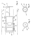
- a machine 11 according to the invention is shown as a device described above for processing a floor surface in the form of a wooden floor 12, which consists of individual plank-like wooden floorboards with joints 13 therebetween, especially at an outdoor terrace.
- the machine 11 as can also be seen from the top view Fig. 2 however, constituting only a part of the machine 11, a left side support 15a and a right side support 15b forming part of a frame.
- a housing 16 is arranged, which occupies the rear two thirds of the machine 11.
- a power electronics can be arranged.
- an impeller 17a or 17b is provided on each of which the machine 11 runs. They are not driven.
- the abrasive brush 19 is mounted on a non-illustrated, for the skilled person, however, easily realized storage, in particular a continuous, connected to the side members 15 axis. To replace the brush 19 against another brush or the order brush, this storage can be quickly and easily detachable.
- a drive motor 25 on top of the housing 16 and a belt drive 26 the brush 19 is driven or rotated in a manner known per se, namely, in Fig. 1 counterclockwise. Thus, it can support a movement of the machine 11 in the machining direction R.
- the machine 11 has a stem 27, which extends in the illustrated embodiment of the housing 16 from the front. It may alternatively be attached to the side rails 15. It can be designed, for example, in the manner of a transverse traverse. At this stem 27 is located above a connecting thread 29, on which a fluid container 31 is screwed. Instead of such a connection thread 29, a different connection may be provided, possibly also as elastically formed plug or the like.
- the fluid container 31 may be a substantially permanently installed container or tank, which is then refilled in each case with fluid.
- he carries on his top a pressure pump 33 with a handle 34, which is optional. By moving the handle 34, for example, up and down as shown by the arrow, the pressure pump 33 can generate an overpressure in the fluid container 31.
- a manually operated pressure pump 33 and an electrically driven pump may be provided.
- a conventional fluid container can be connected and attached to the connecting thread 29, for example a can as a fluid container, as can be purchased normally.
- a prescribed pressure pump can be used for pressurized discharge of the fluid.
- the fluid passes from the fluid container 31 via a metering valve 36 and a fluid line 37 to a Ausbringdüsenology 38. This extends according to Fig. 2 approximately over the width of the brush 19.
- the metering valve 36 By means of the metering valve 36, the discharge of the fluid can be started and the application rate set, as will be explained below.
- the Ausbringdüsenance 38 may be a tube with a plurality of holes in a simple embodiment, which may be advantageous either directly down or slightly obliquely aligned, so that the fluid at least partially reaches or drips on aumpssbürste. This has already been described at the beginning.
- nozzles or spray nozzles may be provided for the fluid when pressurized application occurs. By spraying the fluid above all, a better and more planar distribution can be achieved, in particular directly on the floor surface.
- the machine 11 has a push rod 40 secured to the housing 16, alternatively to a frame. This can be adjustable in height and has at its end a transverse handle 41. Thus, the machine 11 can be moved, in particular pushed in the machine direction R and pulled against this direction. Usually, such a processing of the wooden floor 12 by forward and backward movement of the machine 11.
- On the handle 41 is a metering lever 42 which is connected by means of a Bowden cable 43 with the metering valve 36.
- the amount of fluid dispensed during the processing of the wooden floor 12 can be set permanently and as needed.
- the fluid container 31 may also be arranged on the push rod. So it is also easy to reach, and does not disturb the view of the area in front of the machine 11. Also, a pressure vessel can be arranged here.
- a guide wheel 45 is provided in the plan view Fig. 2 in the right front area.
- This is very narrow or on his Outer edge very narrow, advantageously a few mm, so that it can intervene in the joints 13 of the wooden floor 12, so to speak, and ensures a safe and accurate longitudinal guidance of the machine 11.
- the guide wheel 45 is not driven in a simple embodiment of the invention, but it could be, similar to the wheels 17.
- the weight of the machine 11 in the front not only rests on the brush wheel 19, but in addition a support by the guide wheel 45 takes place. This is less of a benefit during sanding than after application or application of the fluid.
- the guide wheel 45 can be raised or lowered with an adjusting device, not shown, in relation to the brush 19 or its storage. Such adjustment of the guide wheel 45 is advantageously designed manually and continuously.
- abrasive brush 19 around a splash guard 28 is provided as a cover, which also serves as protection against injury from the brush. It may advantageously also be attached to the stem 27 and be designed to be easily replaceable.
- the fluid line 37 passes through it, as well as the Ausbringdüsenance 38 is provided below the splash guard 28.
- it is outside of the splash guard or front of it, so it can be better adjusted from the outside.
- a suction unit for this can be provided either in addition to the machine 11 in the usual way, especially with a kind of dust bag, for example, generally attached to the guide rod.
- it may be provided a suction tube supplied by an external suction.
- An industrial vacuum cleaner or the like for an external suction can remain stationary or be dragged while editing or grinding.
- an application brush 20 is shown having a brush body 21 having a continuous surface 24, such as absorbent material such as foam or fabric. It can also be provided that the surface 24 is removable from the brush body 21 for easier replacement when worn or to adapt to different processing steps.
- Fig. 4 an embodiment of an abrasive brush 19 is shown.
- brush strips 23 are placed in a brush body 21, for example screwed.
- the individual bristles 22 are the individual bristles 22 side by side.
Landscapes
- Engineering & Computer Science (AREA)
- Mechanical Engineering (AREA)
- Finish Polishing, Edge Sharpening, And Grinding By Specific Grinding Devices (AREA)
- Grinding Of Cylindrical And Plane Surfaces (AREA)
- Coating Apparatus (AREA)
- Cleaning In General (AREA)
Applications Claiming Priority (1)
| Application Number | Priority Date | Filing Date | Title |
|---|---|---|---|
| DE200920000444 DE202009000444U1 (de) | 2009-01-12 | 2009-01-12 | Vorrichtung zur Bearbeitung von Bodenflächen |
Publications (3)
| Publication Number | Publication Date |
|---|---|
| EP2206580A2 true EP2206580A2 (fr) | 2010-07-14 |
| EP2206580A3 EP2206580A3 (fr) | 2012-05-16 |
| EP2206580B1 EP2206580B1 (fr) | 2014-04-23 |
Family
ID=40514897
Family Applications (1)
| Application Number | Title | Priority Date | Filing Date |
|---|---|---|---|
| EP20100150528 Not-in-force EP2206580B1 (fr) | 2009-01-12 | 2010-01-12 | Dispositif destiné au traitement de surfaces de sol |
Country Status (2)
| Country | Link |
|---|---|
| EP (1) | EP2206580B1 (fr) |
| DE (1) | DE202009000444U1 (fr) |
Cited By (3)
| Publication number | Priority date | Publication date | Assignee | Title |
|---|---|---|---|---|
| CN112894549A (zh) * | 2021-01-16 | 2021-06-04 | 北京新兴达信建筑工程有限公司 | 一种房屋精装修施工布线管道敷设装置 |
| CN113857957A (zh) * | 2021-06-04 | 2021-12-31 | 北京太和永道商贸有限公司 | 一种用于石材地面的养护装置 |
| EP4046749A1 (fr) | 2021-02-19 | 2022-08-24 | Tyrolit - Schleifmittelwerke Swarovski K.G. | Agencement de distance pour un rouleau de ponçage |
Families Citing this family (1)
| Publication number | Priority date | Publication date | Assignee | Title |
|---|---|---|---|---|
| DE102019104621A1 (de) * | 2019-02-22 | 2020-08-27 | Monti-Werkzeuge Gmbh | Bürstenaggregat |
Citations (1)
| Publication number | Priority date | Publication date | Assignee | Title |
|---|---|---|---|---|
| DE3523903A1 (de) | 1985-07-04 | 1987-01-08 | Karl Hettich | Fussbodenschleifmaschine |
Family Cites Families (2)
| Publication number | Priority date | Publication date | Assignee | Title |
|---|---|---|---|---|
| GB9515334D0 (en) * | 1995-07-26 | 1995-09-20 | Robertshaw Dawn | Abrasive roller |
| US20080014843A1 (en) * | 2005-04-07 | 2008-01-17 | Alto U.S. Inc. | Method and apparatus for refinishing wooden floors |
-
2009
- 2009-01-12 DE DE200920000444 patent/DE202009000444U1/de not_active Expired - Lifetime
-
2010
- 2010-01-12 EP EP20100150528 patent/EP2206580B1/fr not_active Not-in-force
Patent Citations (1)
| Publication number | Priority date | Publication date | Assignee | Title |
|---|---|---|---|---|
| DE3523903A1 (de) | 1985-07-04 | 1987-01-08 | Karl Hettich | Fussbodenschleifmaschine |
Cited By (4)
| Publication number | Priority date | Publication date | Assignee | Title |
|---|---|---|---|---|
| CN112894549A (zh) * | 2021-01-16 | 2021-06-04 | 北京新兴达信建筑工程有限公司 | 一种房屋精装修施工布线管道敷设装置 |
| EP4046749A1 (fr) | 2021-02-19 | 2022-08-24 | Tyrolit - Schleifmittelwerke Swarovski K.G. | Agencement de distance pour un rouleau de ponçage |
| CN114952615A (zh) * | 2021-02-19 | 2022-08-30 | 蒂罗利特磨料机械斯沃罗夫斯基两合公司 | 间隔装置、带间隔装置和磨削辊的系统、磨削机及其应用 |
| CN113857957A (zh) * | 2021-06-04 | 2021-12-31 | 北京太和永道商贸有限公司 | 一种用于石材地面的养护装置 |
Also Published As
| Publication number | Publication date |
|---|---|
| DE202009000444U1 (de) | 2009-04-02 |
| EP2206580A3 (fr) | 2012-05-16 |
| EP2206580B1 (fr) | 2014-04-23 |
Similar Documents
| Publication | Publication Date | Title |
|---|---|---|
| EP2925930B1 (fr) | Procédé et dispositif de meulage d'un rail | |
| DE2624816A1 (de) | Vorrichtung zum behandeln einer flaeche | |
| EP2206580B1 (fr) | Dispositif destiné au traitement de surfaces de sol | |
| DE69501670T2 (de) | Maschine zum Behandeln von Skisohlen, insbesondere durch Schleifen | |
| DE19539586C2 (de) | Gerät zum Reinigen von Oberflächen | |
| DE3145151C2 (de) | Antreibbare Walze zum Überschleifen oder Polieren der Oberfläche einer Fahrzeugkarosserie oder dergleichen | |
| DE2710140A1 (de) | Einrichtung zur mechanischen oberflaechenbehandlung von fahrbahnoberflaechen | |
| DE29504598U1 (de) | Vorrichtung zum Entfernen von einragenden Gegenständen im Innern eines Rohres | |
| DE19632143A1 (de) | Maschine zum Schleifen von Holzrahmen | |
| EP2387933B1 (fr) | Procédé de nettoyage d'une surface au sol et appareil de nettoyage de sol destiné à l'exécution du procédé | |
| DE4009581A1 (de) | Vorrichtung zum aufbereiten feinkoerniger belaege, insbesondere von tennisplaetzen | |
| DE102015102333A1 (de) | Kehrmaschine und Verfahren zum Nachstellen einer Kehrwalze einer Kehrmaschine | |
| EP1838198B1 (fr) | Dispositif de type serpilliere humide a support plat | |
| DE20012140U1 (de) | Vorrichtung zum Herausziehen und Reinigen von Schaberklingen | |
| DE3913378C1 (en) | Grinding dust removal system - uses rotating flexible roller pressed against workpiece | |
| DE4100905A1 (de) | Parkettschleifmaschine | |
| WO1985001457A1 (fr) | Installation de traitement de grandes surfaces verticales, en particulier, de surfaces exterieures de recipients cylindriques verticaux | |
| DE1961409A1 (de) | Vorrichtung zum Behandeln von Druckplatten,Ein- und Mehrschichtenplatten,beispielsweise Offsetplatten mit Fluessigkeiten | |
| DE8712855U1 (de) | Vorrichtung zum Benetzen einer Schleifscheibe einer Brillenglasrandschleifmaschine mit einer Schleifflüssigkeit, insbesondere einer Handschleifmaschine | |
| DE20304089U1 (de) | Reinigungsvorrichtung | |
| DE499756C (de) | Poliergeraet, insbesondere fuer Fussboeden | |
| DE2057466A1 (de) | Einrichtung zur Hoehenverstellung und zum Auswechseln der Reinigungswalze einer Fussbodenreinigungsmaschine | |
| DE2642011A1 (de) | Vorrichtung zum spachteln von ebenen werkstuecken | |
| DE2555308A1 (de) | Vorrichtung zum abschaelen und neubeschichten von strassendecken | |
| CH692137A5 (de) | Feinabsenkbare Bodenschleifmaschine. |
Legal Events
| Date | Code | Title | Description |
|---|---|---|---|
| PUAI | Public reference made under article 153(3) epc to a published international application that has entered the european phase |
Free format text: ORIGINAL CODE: 0009012 |
|
| AK | Designated contracting states |
Kind code of ref document: A2 Designated state(s): AT BE BG CH CY CZ DE DK EE ES FI FR GB GR HR HU IE IS IT LI LT LU LV MC MK MT NL NO PL PT RO SE SI SK SM TR |
|
| AX | Request for extension of the european patent |
Extension state: AL BA RS |
|
| PUAL | Search report despatched |
Free format text: ORIGINAL CODE: 0009013 |
|
| AK | Designated contracting states |
Kind code of ref document: A3 Designated state(s): AT BE BG CH CY CZ DE DK EE ES FI FR GB GR HR HU IE IS IT LI LT LU LV MC MK MT NL NO PL PT RO SE SI SK SM TR |
|
| AX | Request for extension of the european patent |
Extension state: AL BA RS |
|
| RIC1 | Information provided on ipc code assigned before grant |
Ipc: B24B 7/18 20060101AFI20120412BHEP Ipc: A47L 11/18 20060101ALI20120412BHEP |
|
| 17P | Request for examination filed |
Effective date: 20121108 |
|
| GRAP | Despatch of communication of intention to grant a patent |
Free format text: ORIGINAL CODE: EPIDOSNIGR1 |
|
| RIC1 | Information provided on ipc code assigned before grant |
Ipc: A47L 11/18 20060101ALI20131016BHEP Ipc: B24B 7/18 20060101AFI20131016BHEP |
|
| INTG | Intention to grant announced |
Effective date: 20131106 |
|
| GRAS | Grant fee paid |
Free format text: ORIGINAL CODE: EPIDOSNIGR3 |
|
| GRAA | (expected) grant |
Free format text: ORIGINAL CODE: 0009210 |
|
| AK | Designated contracting states |
Kind code of ref document: B1 Designated state(s): AT BE BG CH CY CZ DE DK EE ES FI FR GB GR HR HU IE IS IT LI LT LU LV MC MK MT NL NO PL PT RO SE SI SK SM TR |
|
| REG | Reference to a national code |
Ref country code: GB Ref legal event code: FG4D Free format text: NOT ENGLISH |
|
| REG | Reference to a national code |
Ref country code: CH Ref legal event code: EP |
|
| REG | Reference to a national code |
Ref country code: AT Ref legal event code: REF Ref document number: 663509 Country of ref document: AT Kind code of ref document: T Effective date: 20140515 |
|
| REG | Reference to a national code |
Ref country code: IE Ref legal event code: FG4D Free format text: LANGUAGE OF EP DOCUMENT: GERMAN |
|
| REG | Reference to a national code |
Ref country code: DE Ref legal event code: R096 Ref document number: 502010006722 Country of ref document: DE Effective date: 20140612 |
|
| REG | Reference to a national code |
Ref country code: NL Ref legal event code: VDEP Effective date: 20140423 |
|
| REG | Reference to a national code |
Ref country code: LT Ref legal event code: MG4D |
|
| PG25 | Lapsed in a contracting state [announced via postgrant information from national office to epo] |
Ref country code: NO Free format text: LAPSE BECAUSE OF FAILURE TO SUBMIT A TRANSLATION OF THE DESCRIPTION OR TO PAY THE FEE WITHIN THE PRESCRIBED TIME-LIMIT Effective date: 20140723 Ref country code: FI Free format text: LAPSE BECAUSE OF FAILURE TO SUBMIT A TRANSLATION OF THE DESCRIPTION OR TO PAY THE FEE WITHIN THE PRESCRIBED TIME-LIMIT Effective date: 20140423 Ref country code: NL Free format text: LAPSE BECAUSE OF FAILURE TO SUBMIT A TRANSLATION OF THE DESCRIPTION OR TO PAY THE FEE WITHIN THE PRESCRIBED TIME-LIMIT Effective date: 20140423 Ref country code: IS Free format text: LAPSE BECAUSE OF FAILURE TO SUBMIT A TRANSLATION OF THE DESCRIPTION OR TO PAY THE FEE WITHIN THE PRESCRIBED TIME-LIMIT Effective date: 20140823 Ref country code: GR Free format text: LAPSE BECAUSE OF FAILURE TO SUBMIT A TRANSLATION OF THE DESCRIPTION OR TO PAY THE FEE WITHIN THE PRESCRIBED TIME-LIMIT Effective date: 20140724 Ref country code: BG Free format text: LAPSE BECAUSE OF FAILURE TO SUBMIT A TRANSLATION OF THE DESCRIPTION OR TO PAY THE FEE WITHIN THE PRESCRIBED TIME-LIMIT Effective date: 20140723 Ref country code: CY Free format text: LAPSE BECAUSE OF FAILURE TO SUBMIT A TRANSLATION OF THE DESCRIPTION OR TO PAY THE FEE WITHIN THE PRESCRIBED TIME-LIMIT Effective date: 20140423 Ref country code: LT Free format text: LAPSE BECAUSE OF FAILURE TO SUBMIT A TRANSLATION OF THE DESCRIPTION OR TO PAY THE FEE WITHIN THE PRESCRIBED TIME-LIMIT Effective date: 20140423 |
|
| PG25 | Lapsed in a contracting state [announced via postgrant information from national office to epo] |
Ref country code: ES Free format text: LAPSE BECAUSE OF FAILURE TO SUBMIT A TRANSLATION OF THE DESCRIPTION OR TO PAY THE FEE WITHIN THE PRESCRIBED TIME-LIMIT Effective date: 20140423 Ref country code: HR Free format text: LAPSE BECAUSE OF FAILURE TO SUBMIT A TRANSLATION OF THE DESCRIPTION OR TO PAY THE FEE WITHIN THE PRESCRIBED TIME-LIMIT Effective date: 20140423 Ref country code: SE Free format text: LAPSE BECAUSE OF FAILURE TO SUBMIT A TRANSLATION OF THE DESCRIPTION OR TO PAY THE FEE WITHIN THE PRESCRIBED TIME-LIMIT Effective date: 20140423 Ref country code: PL Free format text: LAPSE BECAUSE OF FAILURE TO SUBMIT A TRANSLATION OF THE DESCRIPTION OR TO PAY THE FEE WITHIN THE PRESCRIBED TIME-LIMIT Effective date: 20140423 Ref country code: LV Free format text: LAPSE BECAUSE OF FAILURE TO SUBMIT A TRANSLATION OF THE DESCRIPTION OR TO PAY THE FEE WITHIN THE PRESCRIBED TIME-LIMIT Effective date: 20140423 |
|
| PG25 | Lapsed in a contracting state [announced via postgrant information from national office to epo] |
Ref country code: PT Free format text: LAPSE BECAUSE OF FAILURE TO SUBMIT A TRANSLATION OF THE DESCRIPTION OR TO PAY THE FEE WITHIN THE PRESCRIBED TIME-LIMIT Effective date: 20140825 |
|
| REG | Reference to a national code |
Ref country code: DE Ref legal event code: R097 Ref document number: 502010006722 Country of ref document: DE |
|
| PG25 | Lapsed in a contracting state [announced via postgrant information from national office to epo] |
Ref country code: EE Free format text: LAPSE BECAUSE OF FAILURE TO SUBMIT A TRANSLATION OF THE DESCRIPTION OR TO PAY THE FEE WITHIN THE PRESCRIBED TIME-LIMIT Effective date: 20140423 Ref country code: DK Free format text: LAPSE BECAUSE OF FAILURE TO SUBMIT A TRANSLATION OF THE DESCRIPTION OR TO PAY THE FEE WITHIN THE PRESCRIBED TIME-LIMIT Effective date: 20140423 Ref country code: RO Free format text: LAPSE BECAUSE OF FAILURE TO SUBMIT A TRANSLATION OF THE DESCRIPTION OR TO PAY THE FEE WITHIN THE PRESCRIBED TIME-LIMIT Effective date: 20140423 Ref country code: CZ Free format text: LAPSE BECAUSE OF FAILURE TO SUBMIT A TRANSLATION OF THE DESCRIPTION OR TO PAY THE FEE WITHIN THE PRESCRIBED TIME-LIMIT Effective date: 20140423 Ref country code: SK Free format text: LAPSE BECAUSE OF FAILURE TO SUBMIT A TRANSLATION OF THE DESCRIPTION OR TO PAY THE FEE WITHIN THE PRESCRIBED TIME-LIMIT Effective date: 20140423 |
|
| PLBE | No opposition filed within time limit |
Free format text: ORIGINAL CODE: 0009261 |
|
| STAA | Information on the status of an ep patent application or granted ep patent |
Free format text: STATUS: NO OPPOSITION FILED WITHIN TIME LIMIT |
|
| PG25 | Lapsed in a contracting state [announced via postgrant information from national office to epo] |
Ref country code: IT Free format text: LAPSE BECAUSE OF FAILURE TO SUBMIT A TRANSLATION OF THE DESCRIPTION OR TO PAY THE FEE WITHIN THE PRESCRIBED TIME-LIMIT Effective date: 20140423 |
|
| 26N | No opposition filed |
Effective date: 20150126 |
|
| REG | Reference to a national code |
Ref country code: DE Ref legal event code: R097 Ref document number: 502010006722 Country of ref document: DE Effective date: 20150126 |
|
| PG25 | Lapsed in a contracting state [announced via postgrant information from national office to epo] |
Ref country code: BE Free format text: LAPSE BECAUSE OF NON-PAYMENT OF DUE FEES Effective date: 20150131 |
|
| PG25 | Lapsed in a contracting state [announced via postgrant information from national office to epo] |
Ref country code: SI Free format text: LAPSE BECAUSE OF FAILURE TO SUBMIT A TRANSLATION OF THE DESCRIPTION OR TO PAY THE FEE WITHIN THE PRESCRIBED TIME-LIMIT Effective date: 20140423 |
|
| REG | Reference to a national code |
Ref country code: DE Ref legal event code: R119 Ref document number: 502010006722 Country of ref document: DE |
|
| REG | Reference to a national code |
Ref country code: CH Ref legal event code: PL |
|
| PG25 | Lapsed in a contracting state [announced via postgrant information from national office to epo] |
Ref country code: LU Free format text: LAPSE BECAUSE OF FAILURE TO SUBMIT A TRANSLATION OF THE DESCRIPTION OR TO PAY THE FEE WITHIN THE PRESCRIBED TIME-LIMIT Effective date: 20150112 |
|
| GBPC | Gb: european patent ceased through non-payment of renewal fee |
Effective date: 20150112 |
|
| PG25 | Lapsed in a contracting state [announced via postgrant information from national office to epo] |
Ref country code: MC Free format text: LAPSE BECAUSE OF FAILURE TO SUBMIT A TRANSLATION OF THE DESCRIPTION OR TO PAY THE FEE WITHIN THE PRESCRIBED TIME-LIMIT Effective date: 20140423 |
|
| PG25 | Lapsed in a contracting state [announced via postgrant information from national office to epo] |
Ref country code: GB Free format text: LAPSE BECAUSE OF NON-PAYMENT OF DUE FEES Effective date: 20150112 Ref country code: LI Free format text: LAPSE BECAUSE OF NON-PAYMENT OF DUE FEES Effective date: 20150131 Ref country code: CH Free format text: LAPSE BECAUSE OF NON-PAYMENT OF DUE FEES Effective date: 20150131 Ref country code: DE Free format text: LAPSE BECAUSE OF NON-PAYMENT OF DUE FEES Effective date: 20150801 |
|
| REG | Reference to a national code |
Ref country code: IE Ref legal event code: MM4A |
|
| REG | Reference to a national code |
Ref country code: FR Ref legal event code: PLFP Year of fee payment: 7 |
|
| PG25 | Lapsed in a contracting state [announced via postgrant information from national office to epo] |
Ref country code: IE Free format text: LAPSE BECAUSE OF NON-PAYMENT OF DUE FEES Effective date: 20150112 |
|
| REG | Reference to a national code |
Ref country code: AT Ref legal event code: MM01 Ref document number: 663509 Country of ref document: AT Kind code of ref document: T Effective date: 20150112 |
|
| PG25 | Lapsed in a contracting state [announced via postgrant information from national office to epo] |
Ref country code: AT Free format text: LAPSE BECAUSE OF NON-PAYMENT OF DUE FEES Effective date: 20150112 |
|
| PG25 | Lapsed in a contracting state [announced via postgrant information from national office to epo] |
Ref country code: MT Free format text: LAPSE BECAUSE OF FAILURE TO SUBMIT A TRANSLATION OF THE DESCRIPTION OR TO PAY THE FEE WITHIN THE PRESCRIBED TIME-LIMIT Effective date: 20140423 |
|
| REG | Reference to a national code |
Ref country code: FR Ref legal event code: PLFP Year of fee payment: 8 |
|
| PG25 | Lapsed in a contracting state [announced via postgrant information from national office to epo] |
Ref country code: SM Free format text: LAPSE BECAUSE OF FAILURE TO SUBMIT A TRANSLATION OF THE DESCRIPTION OR TO PAY THE FEE WITHIN THE PRESCRIBED TIME-LIMIT Effective date: 20140423 Ref country code: HU Free format text: LAPSE BECAUSE OF FAILURE TO SUBMIT A TRANSLATION OF THE DESCRIPTION OR TO PAY THE FEE WITHIN THE PRESCRIBED TIME-LIMIT; INVALID AB INITIO Effective date: 20100112 |
|
| PG25 | Lapsed in a contracting state [announced via postgrant information from national office to epo] |
Ref country code: TR Free format text: LAPSE BECAUSE OF FAILURE TO SUBMIT A TRANSLATION OF THE DESCRIPTION OR TO PAY THE FEE WITHIN THE PRESCRIBED TIME-LIMIT Effective date: 20140423 |
|
| REG | Reference to a national code |
Ref country code: FR Ref legal event code: PLFP Year of fee payment: 9 |
|
| PGFP | Annual fee paid to national office [announced via postgrant information from national office to epo] |
Ref country code: FR Payment date: 20180124 Year of fee payment: 9 |
|
| PG25 | Lapsed in a contracting state [announced via postgrant information from national office to epo] |
Ref country code: MK Free format text: LAPSE BECAUSE OF FAILURE TO SUBMIT A TRANSLATION OF THE DESCRIPTION OR TO PAY THE FEE WITHIN THE PRESCRIBED TIME-LIMIT Effective date: 20140423 |
|
| PG25 | Lapsed in a contracting state [announced via postgrant information from national office to epo] |
Ref country code: FR Free format text: LAPSE BECAUSE OF NON-PAYMENT OF DUE FEES Effective date: 20190131 |