EP2206643A1 - Einbaustruktur für Fahrradbatterie und Steuersystem - Google Patents
Einbaustruktur für Fahrradbatterie und Steuersystem Download PDFInfo
- Publication number
- EP2206643A1 EP2206643A1 EP09150297A EP09150297A EP2206643A1 EP 2206643 A1 EP2206643 A1 EP 2206643A1 EP 09150297 A EP09150297 A EP 09150297A EP 09150297 A EP09150297 A EP 09150297A EP 2206643 A1 EP2206643 A1 EP 2206643A1
- Authority
- EP
- European Patent Office
- Prior art keywords
- battery
- tube
- main frame
- control system
- frame tube
- Prior art date
- Legal status (The legal status is an assumption and is not a legal conclusion. Google has not performed a legal analysis and makes no representation as to the accuracy of the status listed.)
- Withdrawn
Links
Images


Classifications
-
- B—PERFORMING OPERATIONS; TRANSPORTING
- B62—LAND VEHICLES FOR TRAVELLING OTHERWISE THAN ON RAILS
- B62M—RIDER PROPULSION OF WHEELED VEHICLES OR SLEDGES; POWERED PROPULSION OF SLEDGES OR SINGLE-TRACK CYCLES; TRANSMISSIONS SPECIALLY ADAPTED FOR SUCH VEHICLES
- B62M6/00—Rider propulsion of wheeled vehicles with additional source of power, e.g. combustion engine or electric motor
- B62M6/80—Accessories, e.g. power sources; Arrangements thereof
- B62M6/90—Batteries
-
- B—PERFORMING OPERATIONS; TRANSPORTING
- B62—LAND VEHICLES FOR TRAVELLING OTHERWISE THAN ON RAILS
- B62K—CYCLES; CYCLE FRAMES; CYCLE STEERING DEVICES; RIDER-OPERATED TERMINAL CONTROLS SPECIALLY ADAPTED FOR CYCLES; CYCLE AXLE SUSPENSIONS; CYCLE SIDECARS, FORECARS, OR THE LIKE
- B62K19/00—Cycle frames
- B62K19/30—Frame parts shaped to receive other cycle parts or accessories
- B62K19/40—Frame parts shaped to receive other cycle parts or accessories for attaching accessories, e.g. article carriers, lamps
Definitions
- the present invention generally relates to bike battery and control system mounting structures and more particularly relates to a main frame tube located between head tube and stem, having a folder attached to the main frame tube which enables the tube to be folded, where the battery and the control system can be placed into the tube from the tube openings at folding location, and the battery and the control system are mounted therein out of sight.
- the objective of the present invention is to provide a bike battery and control system mounting structure where the battery and the control system are mounted in concealment adequately.
- the main traits of the present invention lie in: the main frame tube is provided with a folder in between the head tube and the stem, which enables the frame tube to be folded, where the battery and the control system can be placed into the tube from the tube opening at folding location, and the battery and the control system are mounted therein out of sight.
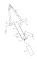
- the present invention is provided with a folder 14 which is attached to the main frame tube 13 located in between head tube 11 and stem 12 of the frame 10, where the folder 14 enables the main frame tube 13 to be folded, shown in FIGS. 2 & 3 .
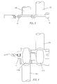
- the first segment of the main frame tube 130, the portion of the main frame tube 130 between the folder 14 and the stem 12, is longer than the second segment of the main frame tube 131, the portion between the folder 14 and the head tube 11. This enables the first segment of the main frame tube 130 to accommodate the battery 20 (shown in FIGS. 6 ), where its outer diameter is fitted well with the inner diameter of the main frame tube 13, provided that the folder 14 is open (shown in FIGS. 4 & 5 ).
- the battery is being tightly mounted in the first segment of the main frame tube 130 and the battery 20 is further barricaded fixedly by a locking pin 15.
- the control system 30 (for instance a printed circuit control board) is placed in the second segment of the main frame tube 131 for a mount through the tube opening 1310. Since the battery 20 and the control system 30 are hided in the main frame tube 13, the overall looks wouldn't be influenced.
- the battery 20 is placed in the first segment of the main frame tube 130 and is close to 5-way pipe 16 which nears the attachment of the motor and the gears that enables the power cord 21 of the battery 20 goes through the shortest distance to connect the motor through the first segment of the main frame tube 130;
- the control system 30 is placed in the second segment of the main frame tube 131, and the power cord 31 of the control system 30 goes through the shortest distance to connect the control unit at the handle through the head tube 11, which simplifies the power control wiring and hides all in the tube.
- the present invention is provided with a folder 14 attached to the main frame tube 13, which enables the battery 20 and the control system 30 to be placed in the main frame tube 13 that makes them mounted in a complete hiding.
- the power control wiring is the minimum connected to the motor and the control unit, which substantially boosts the handiness of the wiring and the elegance of the looks, and is no doubt useful and creative than the prior art.
Landscapes
- Engineering & Computer Science (AREA)
- Chemical & Material Sciences (AREA)
- Combustion & Propulsion (AREA)
- Mechanical Engineering (AREA)
- Transportation (AREA)
- Battery Mounting, Suspending (AREA)
Priority Applications (1)
| Application Number | Priority Date | Filing Date | Title |
|---|---|---|---|
| EP09150297A EP2206643A1 (de) | 2009-01-09 | 2009-01-09 | Einbaustruktur für Fahrradbatterie und Steuersystem |
Applications Claiming Priority (1)
| Application Number | Priority Date | Filing Date | Title |
|---|---|---|---|
| EP09150297A EP2206643A1 (de) | 2009-01-09 | 2009-01-09 | Einbaustruktur für Fahrradbatterie und Steuersystem |
Publications (1)
| Publication Number | Publication Date |
|---|---|
| EP2206643A1 true EP2206643A1 (de) | 2010-07-14 |
Family
ID=40651646
Family Applications (1)
| Application Number | Title | Priority Date | Filing Date |
|---|---|---|---|
| EP09150297A Withdrawn EP2206643A1 (de) | 2009-01-09 | 2009-01-09 | Einbaustruktur für Fahrradbatterie und Steuersystem |
Country Status (1)
| Country | Link |
|---|---|
| EP (1) | EP2206643A1 (de) |
Cited By (2)
| Publication number | Priority date | Publication date | Assignee | Title |
|---|---|---|---|---|
| WO2019037323A1 (zh) * | 2017-08-25 | 2019-02-28 | 金萍 | 一种电动车车架与控制器的连接结构 |
| CN109866626A (zh) * | 2019-04-01 | 2019-06-11 | 南通天缘自动车有限公司 | 一种用于放置电机控制器的管料 |
Citations (2)
| Publication number | Priority date | Publication date | Assignee | Title |
|---|---|---|---|---|
| EP0741441A2 (de) * | 1995-04-28 | 1996-11-06 | Yamaha Hatsudoki Kabushiki Kaisha | Ladeeinheit für eine Batterie |
| EP0905014A2 (de) * | 1997-09-30 | 1999-03-31 | Honda Giken Kogyo Kabushiki Kaisha | Batteriekasten- Montageanordnung für Fahrrad |
-
2009
- 2009-01-09 EP EP09150297A patent/EP2206643A1/de not_active Withdrawn
Patent Citations (2)
| Publication number | Priority date | Publication date | Assignee | Title |
|---|---|---|---|---|
| EP0741441A2 (de) * | 1995-04-28 | 1996-11-06 | Yamaha Hatsudoki Kabushiki Kaisha | Ladeeinheit für eine Batterie |
| EP0905014A2 (de) * | 1997-09-30 | 1999-03-31 | Honda Giken Kogyo Kabushiki Kaisha | Batteriekasten- Montageanordnung für Fahrrad |
Cited By (2)
| Publication number | Priority date | Publication date | Assignee | Title |
|---|---|---|---|---|
| WO2019037323A1 (zh) * | 2017-08-25 | 2019-02-28 | 金萍 | 一种电动车车架与控制器的连接结构 |
| CN109866626A (zh) * | 2019-04-01 | 2019-06-11 | 南通天缘自动车有限公司 | 一种用于放置电机控制器的管料 |
Similar Documents
| Publication | Publication Date | Title |
|---|---|---|
| US20100175939A1 (en) | Bike battery and control system mounting structure | |
| JP5674123B2 (ja) | コネクタ固定構造 | |
| EP2206643A1 (de) | Einbaustruktur für Fahrradbatterie und Steuersystem | |
| JP5045169B2 (ja) | 換気装置 | |
| JP5752395B2 (ja) | 操作ユニット | |
| EP1973203A3 (de) | Elektrischer Verbinder mit Hebel und Hebelschutzmantel | |
| CN201737098U (zh) | 摩托车点火器在车架上的安装结构 | |
| JP5100957B2 (ja) | ガスバッグモジュール | |
| CN104787224A (zh) | 一种中置电机系统与吊架的装配结构 | |
| CN208576514U (zh) | 线束安装支架和车辆 | |
| CN103148364A (zh) | 直管形led灯用照明系统 | |
| JP6361087B2 (ja) | ケーブル保持構造およびそれを備えた電気機器およびケーブル保持構造を用いたケーブル配線システム | |
| CN210123922U (zh) | 一种马达 | |
| EP2381047B1 (de) | Lampe für ein rohrförmiges Oberlicht | |
| CN201517759U (zh) | 一种led灯管电极 | |
| CN207579780U (zh) | 一种改进的车尾摄像头 | |
| CN202889838U (zh) | 一种控制器线束安装结构 | |
| JP4949954B2 (ja) | 給電装置のハーネス配索構造 | |
| CN215579237U (zh) | 一种集成控制电路内藏于枪头内部的电动汽车充电枪 | |
| CN222422479U (zh) | 一种用于连接器的护线壳 | |
| CN221293962U (zh) | 车头腕组及车辆 | |
| CN204775755U (zh) | 一种智能自行车线缆 | |
| CN212085440U (zh) | 一种便于内部排线的照明配电箱 | |
| CN205202913U (zh) | 一种发动机上的防火墙护套 | |
| CN210083439U (zh) | 一种隐藏线路的车把组件 |
Legal Events
| Date | Code | Title | Description |
|---|---|---|---|
| PUAI | Public reference made under article 153(3) epc to a published international application that has entered the european phase |
Free format text: ORIGINAL CODE: 0009012 |
|
| 17P | Request for examination filed |
Effective date: 20100326 |
|
| AK | Designated contracting states |
Kind code of ref document: A1 Designated state(s): AT BE BG CH CY CZ DE DK EE ES FI FR GB GR HR HU IE IS IT LI LT LU LV MC MK MT NL NO PL PT RO SE SI SK TR |
|
| AX | Request for extension of the european patent |
Extension state: AL BA RS |
|
| 17Q | First examination report despatched |
Effective date: 20101223 |
|
| STAA | Information on the status of an ep patent application or granted ep patent |
Free format text: STATUS: THE APPLICATION HAS BEEN WITHDRAWN |
|
| AKX | Designation fees paid |
Designated state(s): AT BE BG CH CY CZ DE DK EE ES FI FR GB GR HR HU IE IS IT LI LT LU LV MC MK MT NL NO PL PT RO SE SI SK TR |
|
| 18W | Application withdrawn |
Effective date: 20110303 |