EP2206686A2 - Appareil de désionisation et son procédé de commande - Google Patents
Appareil de désionisation et son procédé de commande Download PDFInfo
- Publication number
- EP2206686A2 EP2206686A2 EP09167123A EP09167123A EP2206686A2 EP 2206686 A2 EP2206686 A2 EP 2206686A2 EP 09167123 A EP09167123 A EP 09167123A EP 09167123 A EP09167123 A EP 09167123A EP 2206686 A2 EP2206686 A2 EP 2206686A2
- Authority
- EP
- European Patent Office
- Prior art keywords
- electrodes
- piezoelectric element
- deionization apparatus
- ions
- porous carbon
- Prior art date
- Legal status (The legal status is an assumption and is not a legal conclusion. Google has not performed a legal analysis and makes no representation as to the accuracy of the status listed.)
- Granted
Links
Images



Classifications
-
- C—CHEMISTRY; METALLURGY
- C02—TREATMENT OF WATER, WASTE WATER, SEWAGE, OR SLUDGE
- C02F—TREATMENT OF WATER, WASTE WATER, SEWAGE, OR SLUDGE
- C02F1/00—Treatment of water, waste water, or sewage
- C02F1/46—Treatment of water, waste water, or sewage by electrochemical methods
- C02F1/469—Treatment of water, waste water, or sewage by electrochemical methods by electrochemical separation, e.g. by electro-osmosis, electrodialysis, electrophoresis
- C02F1/4691—Capacitive deionisation
-
- C—CHEMISTRY; METALLURGY
- C02—TREATMENT OF WATER, WASTE WATER, SEWAGE, OR SLUDGE
- C02F—TREATMENT OF WATER, WASTE WATER, SEWAGE, OR SLUDGE
- C02F1/00—Treatment of water, waste water, or sewage
- C02F1/46—Treatment of water, waste water, or sewage by electrochemical methods
- C02F1/469—Treatment of water, waste water, or sewage by electrochemical methods by electrochemical separation, e.g. by electro-osmosis, electrodialysis, electrophoresis
-
- C—CHEMISTRY; METALLURGY
- C02—TREATMENT OF WATER, WASTE WATER, SEWAGE, OR SLUDGE
- C02F—TREATMENT OF WATER, WASTE WATER, SEWAGE, OR SLUDGE
- C02F1/00—Treatment of water, waste water, or sewage
- C02F1/46—Treatment of water, waste water, or sewage by electrochemical methods
-
- C—CHEMISTRY; METALLURGY
- C02—TREATMENT OF WATER, WASTE WATER, SEWAGE, OR SLUDGE
- C02F—TREATMENT OF WATER, WASTE WATER, SEWAGE, OR SLUDGE
- C02F1/00—Treatment of water, waste water, or sewage
- C02F1/34—Treatment of water, waste water, or sewage with mechanical oscillations
- C02F1/36—Treatment of water, waste water, or sewage with mechanical oscillations ultrasonic vibrations
-
- C—CHEMISTRY; METALLURGY
- C02—TREATMENT OF WATER, WASTE WATER, SEWAGE, OR SLUDGE
- C02F—TREATMENT OF WATER, WASTE WATER, SEWAGE, OR SLUDGE
- C02F1/00—Treatment of water, waste water, or sewage
- C02F1/46—Treatment of water, waste water, or sewage by electrochemical methods
- C02F1/461—Treatment of water, waste water, or sewage by electrochemical methods by electrolysis
- C02F1/46104—Devices therefor; Their operating or servicing
- C02F1/46109—Electrodes
- C02F2001/46119—Cleaning the electrodes
-
- C—CHEMISTRY; METALLURGY
- C02—TREATMENT OF WATER, WASTE WATER, SEWAGE, OR SLUDGE
- C02F—TREATMENT OF WATER, WASTE WATER, SEWAGE, OR SLUDGE
- C02F1/00—Treatment of water, waste water, or sewage
- C02F1/46—Treatment of water, waste water, or sewage by electrochemical methods
- C02F1/461—Treatment of water, waste water, or sewage by electrochemical methods by electrolysis
- C02F1/46104—Devices therefor; Their operating or servicing
- C02F1/46109—Electrodes
- C02F2001/46133—Electrodes characterised by the material
-
- C—CHEMISTRY; METALLURGY
- C02—TREATMENT OF WATER, WASTE WATER, SEWAGE, OR SLUDGE
- C02F—TREATMENT OF WATER, WASTE WATER, SEWAGE, OR SLUDGE
- C02F1/00—Treatment of water, waste water, or sewage
- C02F1/46—Treatment of water, waste water, or sewage by electrochemical methods
- C02F1/461—Treatment of water, waste water, or sewage by electrochemical methods by electrolysis
- C02F1/46104—Devices therefor; Their operating or servicing
- C02F1/46109—Electrodes
- C02F2001/46152—Electrodes characterised by the shape or form
- C02F2001/46157—Perforated or foraminous electrodes
- C02F2001/46161—Porous electrodes
-
- C—CHEMISTRY; METALLURGY
- C02—TREATMENT OF WATER, WASTE WATER, SEWAGE, OR SLUDGE
- C02F—TREATMENT OF WATER, WASTE WATER, SEWAGE, OR SLUDGE
- C02F2101/00—Nature of the contaminant
- C02F2101/10—Inorganic compounds
- C02F2101/12—Halogens or halogen-containing compounds
- C02F2101/14—Fluorine or fluorine-containing compounds
-
- C—CHEMISTRY; METALLURGY
- C02—TREATMENT OF WATER, WASTE WATER, SEWAGE, OR SLUDGE
- C02F—TREATMENT OF WATER, WASTE WATER, SEWAGE, OR SLUDGE
- C02F2101/00—Nature of the contaminant
- C02F2101/10—Inorganic compounds
- C02F2101/20—Heavy metals or heavy metal compounds
-
- C—CHEMISTRY; METALLURGY
- C02—TREATMENT OF WATER, WASTE WATER, SEWAGE, OR SLUDGE
- C02F—TREATMENT OF WATER, WASTE WATER, SEWAGE, OR SLUDGE
- C02F2101/00—Nature of the contaminant
- C02F2101/10—Inorganic compounds
- C02F2101/20—Heavy metals or heavy metal compounds
- C02F2101/203—Iron or iron compound
-
- C—CHEMISTRY; METALLURGY
- C02—TREATMENT OF WATER, WASTE WATER, SEWAGE, OR SLUDGE
- C02F—TREATMENT OF WATER, WASTE WATER, SEWAGE, OR SLUDGE
- C02F2101/00—Nature of the contaminant
- C02F2101/30—Organic compounds
-
- C—CHEMISTRY; METALLURGY
- C02—TREATMENT OF WATER, WASTE WATER, SEWAGE, OR SLUDGE
- C02F—TREATMENT OF WATER, WASTE WATER, SEWAGE, OR SLUDGE
- C02F2103/00—Nature of the water, waste water, sewage or sludge to be treated
- C02F2103/08—Seawater, e.g. for desalination
-
- C—CHEMISTRY; METALLURGY
- C02—TREATMENT OF WATER, WASTE WATER, SEWAGE, OR SLUDGE
- C02F—TREATMENT OF WATER, WASTE WATER, SEWAGE, OR SLUDGE
- C02F2201/00—Apparatus for treatment of water, waste water or sewage
- C02F2201/46—Apparatus for electrochemical processes
- C02F2201/461—Electrolysis apparatus
- C02F2201/46105—Details relating to the electrolytic devices
- C02F2201/4616—Power supply
- C02F2201/4617—DC only
-
- C—CHEMISTRY; METALLURGY
- C02—TREATMENT OF WATER, WASTE WATER, SEWAGE, OR SLUDGE
- C02F—TREATMENT OF WATER, WASTE WATER, SEWAGE, OR SLUDGE
- C02F2303/00—Specific treatment goals
- C02F2303/16—Regeneration of sorbents, filters
Definitions
- One or more embodiments relate to a deionization apparatus to regenerate an electrode using vibration and a method of controlling the same.
- Water and, more particularly, subterranean water contains large amounts of minerals such as calcium, magnesium and so on.
- concentration of calcium or magnesium is called hardness
- water having a high mineral concentration is called hard water
- water having a relatively low mineral concentration is called soft water.
- hard water that is water having high hardness
- electric home appliances such as a washing machine or a dish washer
- the water reacts with a detergent and thus detergency is deteriorated.
- a large amount of scales accumulate on a channel in which the water flows, and thus product reliability is deteriorated.
- the soft water machine using the ion exchange resin softens water by exchanging Ca2+ and Mg2+ ions of hard water components included in water with Na+ of NaCl injected into the ion exchange resin.
- NaCl is periodically injected, and the ion exchange resin is replaced with a new one due to impurities contained in the water.
- the method using the ion exchange resin is uneconomical, because an acidic or basic solution is used when the resin is regenerated and a large amount of polymer resin and chemicals are used in order to treat a large amount of water.
- CDI capacitive deionization
- a CDI technique is based on a simple principle that power is applied to two porous electrodes such that negative ions are electrically absorbed to a positive electrode and positive ions are electrically absorbed to a negative electrode so as to eliminate ions dissolved in a fluid such as water.
- the electrodes are saturated with absorbed ions, the polarities of the electrodes are reversed or the power is turned off so as to separate (desorb) the ions absorbed to the electrodes. Therefore, the regeneration of the electrodes is simply performed.
- a deionization apparatus including electrodes to which ions contained in a fluid are absorbed, and a piezoelectric element to separate the ions absorbed by the electrodes by vibration.
- the piezoelectric element may be a polyvinylidene fluoride (PVDF) piezoelectric plate to generate the vibration by electricity.
- PVDF polyvinylidene fluoride
- the electrodes may include a positive electrode and a negative electrode, and the piezoelectric element may be disposed between the positive electrode and the negative electrode.
- the piezoelectric element may have a porous structure to allow passage of the fluid.
- the electrodes may include a current collector and a porous carbon electrode, and the piezoelectric element may be disposed between the current collector and the porous carbon electrode.
- a spacer may be filled between a porous carbon electrode of one of the electrodes, and a porous carbon electrode of another one of the electrodes.
- the electrodes may include a current collector and a porous carbon electrode, and the current collector may be disposed between the piezoelectric element and the porous carbon electrode.
- the deionization apparatus may further include a generator to apply a sine wave signal to the electrodes so as to generate the vibration of the piezoelectric element.
- the deionization apparatus may further include a power amplifier to amplify the sine wave signal to a predetermined voltage to operate the piezoelectric element.
- the deionization apparatus may further include a DC power source to apply a DC voltage to the electrodes in order to absorb the ions of the fluid, and a capacitor disposed between the DC power source and the power amplifier so as not to apply the DC voltage to the power amplifier.
- a deionization apparatus including an ion sensor to detect an amount of ions absorbed by electrodes, and a controller to compare the amount of ions with a reference value and control the ions absorbed by the electrodes to be separated by a vibration of a piezoelectric element.
- the piezoelectric element may be a polyvinylidene fluoride (PVDF) piezoelectric plate to generate the vibration by electricity.
- PVDF polyvinylidene fluoride
- the electrodes may include a positive electrode and a negative electrode, and the piezoelectric element may be disposed between the positive electrode and the negative electrode.
- the piezoelectric element may have a porous structure to allow passage of the fluid.
- the electrodes may include a current collector and a porous carbon electrode, and the piezoelectric element may be disposed between the current collector and the porous carbon electrode.
- the electrodes may include a current collector and a porous carbon electrode, and the current collector may be disposed between the piezoelectric element and the porous carbon electrode.
- the deionization apparatus may further include a generator to apply a sine wave signal to the electrodes so as to generate the vibration of the piezoelectric element, and a power amplifier to amplify the sine wave signal to a predetermined voltage to operate the piezoelectric element.
- the deionization apparatus may further include a DC power source to apply a DC voltage to the electrodes in order to absorb the ions of the fluid, and a capacitor disposed between the DC power source and the power amplifier so as not to apply the DC voltage to the power amplifier.
- a method of controlling a deionization apparatus including detecting the amount of ions absorbed by electrodes, and separating the ions absorbed to the electrodes by the vibration of a piezoelectric element.
- the separating the ions may occur upon detecting that the amount of ions is in excess of the reference value.
- the separating of the ions by the vibration may include applying a sine wave signal to the electrodes such that the piezoelectric element vibrates.
- the separating of the ions by the vibration may include amplifying the sine wave signal to a predetermined level and applying the amplified sine wave signal to the electrodes such that the piezoelectric element vibrates.
- the separating of the ions may be by an amplifying of the sine wave signal to provide electrical impedance matching.
- the separating of the ions may use ultrasonic waves.
- the separated ions may be removed from a deionization apparatus by fluid moving between the electrodes.
- the ions absorbed to the electrodes are desorbed using the ultrasonic wave, it may be possible to more rapidly perform the regeneration of the deionization apparatus.
- FIG. 1 is a schematic view showing the configuration of a deionization apparatus according to one or more embodiments.
- the deionization apparatus may include current collectors 13 to which power is applied, electrodes 11 and 12 formed of porous carbon, a DC power source 20 to apply a voltage having a predetermined level to the electrodes 11 and 12, a piezoelectric element 21 disposed between the positive electrode 11 and the negative electrode 12 of the carbon electrodes 11 and 12 to generate vibration, a generator 23 to apply a sine wave signal in a predetermined range to the current collectors 13, a power amplifier 22 to amplify the sine wave signal applied by the generator 23, and a plurality of capacitors C1 and C2 disposed between the DC power source 20 and the power amplifier 22 in order to prevent the DC voltage from being applied to the power amplifier 22.
- the current collectors 13 may be formed of conductive rubber or a metal foam material such as nickel (Ni), aluminum (Al) or titanium (Ti).
- Capacitor electrodes 11 and 12 may be manufactured by pressing porous carbon using a high-pressure press. In addition, a potential difference may be generated between the positive electrode 11 and the negative electrode 12 of the capacitor electrodes, by applying power to the current collectors 13.
- the electrodes 11 and 12 formed of the porous carbon may be manufactured using a monolithic carbon aerogel composite (CAC) electrode material manufactured by sol-gel polymerization of resorcinol and formaldehyde.
- CAC monolithic carbon aerogel composite
- the gaps of the porous carbon electrodes 11 and 12 do not have a micropore form, but have a mesopore form such that ions are rapidly penetrated and spread.
- an electrolyzer to improve the durability of the porous carbon electrodes 11 and 12 may be manufactured, and the durability may be improved by utilizing the carbon electrodes together with the current collectors.
- the DC power 20 applies a voltage having a predetermined level to the current collectors 13 so as to generate a potential difference between the electrodes 11 and 12. Meanwhile, the level of the DC voltage applied to the electrodes 11 and 12 has an influence on the ion mass transfer of a fluid. As the voltage is increased, the ion mass transfer is increased, and, as the voltage is decreased, the ion mass transfer is decreased. Accordingly, the DC voltage is adjusted in order to adjust the properties of the treated fluid. For example, a DC voltage having a voltage level which is generally selectable in a range from about 0V to 330 V or in a range from 30 V to 300 V is generated.
- negative ions are electrically absorbed to the positive electrode 11 and positive ions are electrically absorbed to the negative electrode 12, thereby eliminating the ions from the fluid (liquid and gas).
- an electrolyte (seawater or waste water) having various negative ions and positive ions passes between the two positive and negative electrodes 11 and 12 using a porous Activated Carbon Powder (ACP) sheet having a high specific surface area and electric double layer capacitor characteristics, a monolithic CAC sheet or a conductive polymer having pseudo capacitor characteristics and metal oxide or a composite material thereof as an electrode material, ionic impurities, that is, non-oxidation/reduction organic or inorganic negative and positive ions, such as OH-, Cl-, F-, and HCO3- and Li+, Na+, and K+, are eliminated by a difference between the voltages applied to the two electrode sheets of about 0.6 to 1.2 V, and reduced positive ions such as Cu2+, Fe2+, Pb2+, and Cd2+ are separated from the electrolyte so as to be ionically absorbed to the surfaces of the fine pores of the porous carbon electrodes of the two electrochemical capacitor electrodes 11 and 12 by an electric double layer or
- the piezoelectric element 21 generates mechanical force when electricity is applied thereto.
- a polyvinylidene fluoride (PVDF) piezoelectric plate which allows a fluid to pass between the two carbon electrodes 11 and 12 may be used as the piezoelectric element 21.
- the PVDF piezoelectric plate is formed of polyvinylidene fluoride and may be disposed between the positive electrode 11 and the negative electrode 12 of the carbon electrodes 11 and 12.
- the PVDF piezoelectric plate 21 vibrates due to a piezoelectric effect.
- the vibration is supplied to the carbon electrodes 11 and 12 via the fluid in the ultrasonic form. That is, the PVDF piezoelectric plate 21 generates an ultrasonic wave as an ultrasonic actuator.
- the PVDF piezoelectric plate 21 may be formed of a porous material, which is described in detail in U.S. Patent No. 6,146,747 .
- the generator 23 applies a sine wave signal having a predetermined frequency to the current collectors 13.
- the generator 23 applies a sine wave signal having a frequency of 20 kHz to 40 kHz and an effective value of 10 V to the current collectors 13, which are conditions to generate an ultrasonic wave having adequate intensity of about 0.5 watt/m2 by the PVDF piezoelectric plate 21.
- the conditions may be changed according to the deionization apparatus.
- the power amplifier 22 amplifies the amplitude of the sine wave signal applied by the generator 23.
- the amplitude of the sine wave signal generated by the generator 23 and having the frequency of 20 kHz to 40 kHz and the effective value of 10 V is increased so as to provide electrical impedance matching.
- the capacitors C1 and C2 are disposed between the DC power 20 and the power amplifier 22 such that a DC voltage is not applied to the generator 23 and the power amplifier 22.
- FIG. 2 is a schematic view showing the configuration of a deionization apparatus according to one or more embodiments. The same portions as FIG. 1 will be denoted by the same reference numerals.
- the deionization apparatus includes current collectors 13 to which power is applied, porous carbon electrodes 11 and 12, a DC power source 20 to apply a voltage having a predetermined level to the electrodes, a piezoelectric element 21 disposed between the positive electrode 11 and the negative electrode 12 of the carbon electrodes 11 and 12 to generate vibration, a generator 23 to apply a sine wave signal in a predetermined range to the current collectors 13, a power amplifier 22 to amplify the sine wave signal applied by the generator 23, and a plurality of capacitors C1 and C2 disposed between the DC power source 20 and the power amplifier 22 in order to prevent the DC voltage from being applied to the power amplifier 22.
- FIG. 2 The configuration of FIG. 2 is different from that of FIG. 1 in a position where the piezoelectric element 21 is disposed. That is, the PVDF piezoelectric plate which may be used as the piezoelectric element 21 is disposed between the current collectors 13 and the carbon electrodes 11 and 12 so as to desorb the ions absorbed to the carbon electrodes 11 and 12.
- the piezoelectric element 21 disposed between the current collectors 13 and the carbon electrodes 11 and 12, that is, the PVDF piezoelectric plate generates mechanical vibration. Such vibration directly travels to the carbon electrodes 11 and 12 so as to separate the ions.
- a spacer 30 having an average gap or opening having a diameter of about 10 ⁇ m or more may be filled between the positive electrode 11 and the negative electrode 12, in order to provide uniform fluid flow.
- FIG. 3 is a schematic view showing the configuration of a deionization apparatus according to one or more embodiments.
- the same portions as FIG. 1 or FIG. 2 will be denoted by the same reference numerals.
- FIG. 3 The configuration of FIG. 3 is different from those of FIGS. 1 and 2 in a position where the piezoelectric element 21 is disposed. That is, the PVDF piezoelectric plate which may be used as the piezoelectric element 21 is provided on each of the outer surfaces of the electrodes 11 and 12, that is, each of the outer surfaces of the current collectors 13, so as to desorb the ions absorbed to the carbon electrodes 11 and 12.
- the piezoelectric element 21 provided on each of the outer surfaces of the current collectors 13, that is, the PVDF piezoelectric plate, generates mechanical vibration. Such vibration travels to the carbon electrodes 11 and 12 via the current collectors 13 so as to separate the ions.
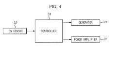
- FIG. 4 is a control block diagram of a deionization apparatus according to one or more embodiments.
- the deionization apparatus includes an ion sensor 32 to sense the amount of ions which are present in a fluid, a generator 23 to apply a sine wave signal to the current collectors 13, and a power amplifier 22 to amplify the sine wave signal applied by the generator 23.
- the ion sensor 32 senses the amount of ions absorbed to the electrodes 11 and 12 ( FIGS. 1 , 2 , and 3 ) of the deionization apparatus and transmits information on the amount of ions to a controller 31.
- the generator 23 applies a sine wave signal having a predetermined frequency to the current collectors 13 ( FIGS. 1 , 2 , and 3 ).
- the generator 23 may apply a sine wave signal having a frequency of 20 kHz to about 40 kHz and an effective value of 10 V to the current collectors 13 ( FIGS. 1 , 2 , and 3 ), which are conditions to generate an ultrasonic wave having adequate intensity of about 0.5 watt/m2 in the PVDF piezoelectric plate of the piezoelectric element of an embodiment of the present invention.
- the power amplifier 22 amplifies the sine wave signal applied to the generator 23.
- the amplitude of the sine wave signal generated by the generator 23 and having the frequency of 20 kHz to 40 kHz and the effective value of 10 V is increased so as to provide electrical impedance matching.
- the controller 31 controls a signal to be transmitted to the DC power source 20 ( FIGS. 1 , 2 , and 3 ) such that the voltage having the predetermined level is applied to the current collectors 13 ( FIGS. 1 , 2 , and 3 ), and controls a potential difference to be generated between the positive electrode and the negative electrode of the carbon electrodes 11 and 12 ( FIGS. 1 , 2 , and 3 ), thereby controlling the ions of the fluid to be absorbed.
- the controller 31 compares the amount of ions transmitted from the ion sensor 32 with a reference value and begins regeneration of the deionization apparatus if the amount of ions of the fluid is greater than the reference value. That is, in order to eliminate the ions absorbed to the carbon electrodes 11 and 12 ( FIGS. 1 , 2 , and 3 ), the signal is transmitted such that the generator 23 applies a sine wave signal having the predetermined frequency and the effective value, and a sine wave amplification signal is transmitted to the power amplifier 22 such that sufficient mechanical energy is emitted from the piezoelectric element 21 ( FIGS. 1 , 2 , and 3 ).
- the method of starting the operation to separate the ions with which the electrodes of the deionization apparatus are saturated is not limited to the above-described method.
- Various methods including a method of deciding a regeneration start operation using a current sensor or starting an ion separating operation in a predetermined period may be used.
- FIG. 5 is a flowchart illustrating a method of controlling a deionization apparatus according to one or more embodiments.
- the ion sensor 32 senses the amount of ions absorbed to the electrodes of the deionization apparatus.
- the fluid passes between the carbon electrodes 11 and 12 such that ionic impurities, that is, non-oxidation/reduction organic or inorganic negative ions and positive ions, such as OH-, Cl-, F-, and HCO3- and Li+, Na+, and K+, are eliminated and reduced positive ions such as Cu2+, Fe2+, Pb2+, and Cd2+ are separated from the electrolyte so as to be ionically absorbed to the surfaces of the fine pores of the porous carbon electrodes of the two electrochemical capacitor electrodes 11 and 12 by the electric double layer.
- ionic impurities that is, non-oxidation/reduction organic or inorganic negative ions and positive ions, such as OH-, Cl-, F-, and HCO3- and Li+, Na+, and K+
- reduced positive ions such as Cu2+, Fe2+, Pb2+, and Cd2+ are separated from the electrolyte so as to be ionically absorbed to the surfaces of the
- the controller 31 compares the sensed amount of ions with the reference value.
- the reference value is arbitrarily determined by a designer as necessary and may be changed according to the use of the deionization apparatus. If is it determined that the sensed amount of ions is greater than or equal to the reference value, the method advances to operation S30. If it is determined that the sensed amount of ions is not greater than or equal to the reference value, the method returns to operation S10.
- the generator 23 applies the sine wave signal to the electrodes 11 and 12. That is, when the regeneration operation of the deionization apparatus is started, the generator 23 may apply the sine wave signal having the frequency of 20 kHz to 40 kHz and the effective value of 10 V to the current collectors 13 .
- the power amplifier 22 amplifies the sine wave signal applied by the generator 23 and applies the amplified sine wave signal to the electrodes 11 and 12.
- the power amplifier 22 amplifies the sine wave signal output from the generator 23 to a predetermined voltage to generate sufficient mechanical energy to provide electrical impedance matching.
- the piezoelectric element 21 when the sine wave signal is applied to the electrodes 11 and 12, the piezoelectric element 21 generates mechanical energy by a piezoelectric effect.
- the mechanical energy generates the ultrasonic wave via the fluid, and the ultrasonic wave is supplied to the electrodes so as to separate the ions. That is, the piezoelectric element 21, which may be the PVDF piezoelectric plate 21, generates the ultrasonic wave as the ultrasonic actuator.
- the piezoelectric element 21 in an arrangement where the piezoelectric element 21 is provided between the carbon electrodes 11 and 12 and the current collectors 13 or is provided outside the current collectors 13, the mechanical energy of the piezoelectric element 21 directly travels to the carbon electrodes 11 and 12 so as to separate the ions.
- the ions separated by the above-described method are washed out by the fluid which moves between the carbon electrodes 11 and 12.
Landscapes
- Chemical & Material Sciences (AREA)
- Chemical Kinetics & Catalysis (AREA)
- Life Sciences & Earth Sciences (AREA)
- Engineering & Computer Science (AREA)
- Electrochemistry (AREA)
- General Chemical & Material Sciences (AREA)
- Hydrology & Water Resources (AREA)
- Environmental & Geological Engineering (AREA)
- Water Supply & Treatment (AREA)
- Organic Chemistry (AREA)
- Analytical Chemistry (AREA)
- Molecular Biology (AREA)
- Health & Medical Sciences (AREA)
- Water Treatment By Electricity Or Magnetism (AREA)
- Separation Using Semi-Permeable Membranes (AREA)
Applications Claiming Priority (1)
| Application Number | Priority Date | Filing Date | Title |
|---|---|---|---|
| KR1020080131499A KR101714535B1 (ko) | 2008-12-22 | 2008-12-22 | 탈이온화 장치 및 그 제어방법 |
Publications (3)
| Publication Number | Publication Date |
|---|---|
| EP2206686A2 true EP2206686A2 (fr) | 2010-07-14 |
| EP2206686A3 EP2206686A3 (fr) | 2011-03-09 |
| EP2206686B1 EP2206686B1 (fr) | 2020-06-24 |
Family
ID=42084490
Family Applications (1)
| Application Number | Title | Priority Date | Filing Date |
|---|---|---|---|
| EP09167123.0A Active EP2206686B1 (fr) | 2008-12-22 | 2009-08-04 | Appareil de désionisation |
Country Status (4)
| Country | Link |
|---|---|
| US (1) | US8753499B2 (fr) |
| EP (1) | EP2206686B1 (fr) |
| KR (1) | KR101714535B1 (fr) |
| CN (1) | CN101759254B (fr) |
Cited By (2)
| Publication number | Priority date | Publication date | Assignee | Title |
|---|---|---|---|---|
| EP2857086A4 (fr) * | 2012-06-04 | 2015-07-29 | Coway Co Ltd | Filtre de déionisation, appareil de traitement de l'eau comprenant un filtre de déionisation et procédé de régénération d'un filtre de déionisation |
| US9289107B2 (en) | 2011-12-13 | 2016-03-22 | Ecolab Usa Inc. | Dishmachine |
Families Citing this family (13)
| Publication number | Priority date | Publication date | Assignee | Title |
|---|---|---|---|---|
| KR20130061366A (ko) * | 2011-12-01 | 2013-06-11 | 삼성전자주식회사 | 축전식탈염장치 |
| CN102603039A (zh) * | 2012-01-19 | 2012-07-25 | 清华大学 | 耦合脱盐方法及装置 |
| US20130277305A1 (en) * | 2012-04-19 | 2013-10-24 | Lockheed Martin Corporation | Selectively perforated graphene membranes for compound harvest, capture and retention |
| CN102690004B (zh) * | 2012-06-12 | 2013-09-04 | 爱思特水务科技有限公司 | 一种电吸附模块改性系统及工艺 |
| KR20150061323A (ko) * | 2013-11-27 | 2015-06-04 | 삼성전자주식회사 | 전기 흡착 탈이온 전극 재생 방법 |
| JP6342838B2 (ja) * | 2014-06-25 | 2018-06-13 | 東京エレクトロン株式会社 | 処理液供給方法、処理液供給装置及びコンピュータ読み取り可能な記録媒体 |
| CN104132467B (zh) * | 2014-08-05 | 2018-05-08 | 海信集团有限公司 | 一种防触电式电热水器 |
| EP3045431A1 (fr) * | 2015-01-16 | 2016-07-20 | DWI - Leibniz-Institut für Interaktive Materialien e.V. | Appareil et procédé de dessalement d'eau continu et séparation d'ions par désionisation capacitive d'électrode d'écoulement |
| CN107523705B (zh) * | 2017-08-09 | 2019-07-02 | 中南大学 | 一种利用两段电容去离子法选择性分离高铼酸根的方法 |
| CN108483591B (zh) * | 2018-04-24 | 2021-07-30 | 浙江工业大学 | 一种提取锂离子的方法 |
| DE102019217482A1 (de) * | 2019-11-13 | 2021-05-20 | Robert Bosch Gmbh | Verfahren zum kapazitiven Deionisieren von Wasser |
| CN112875945A (zh) * | 2021-04-15 | 2021-06-01 | 浙江安耐杰科技股份有限公司 | 一种电化学循环水处理系统及其工艺 |
| AU2022382441B2 (en) | 2021-11-05 | 2025-02-27 | Mitsubishi Kakoki Kaisha,Ltd. | Filtration device, and filtration system |
Citations (1)
| Publication number | Priority date | Publication date | Assignee | Title |
|---|---|---|---|---|
| US6146747A (en) | 1997-01-22 | 2000-11-14 | Usf Filtration And Separations Group Inc. | Highly porous polyvinylidene difluoride membranes |
Family Cites Families (27)
| Publication number | Priority date | Publication date | Assignee | Title |
|---|---|---|---|---|
| SU1095065A2 (ru) * | 1979-11-05 | 1984-05-30 | Вильнюсский Филиал Экспериментального Научно-Исследовательского Института Металлорежущих Станков | Измерительна головка |
| US4569728A (en) * | 1984-11-01 | 1986-02-11 | The United States Of America As Represented By The Secretary Of The Air Force | Selective anodic oxidation of semiconductors for pattern generation |
| US5425858A (en) * | 1994-05-20 | 1995-06-20 | The Regents Of The University Of California | Method and apparatus for capacitive deionization, electrochemical purification, and regeneration of electrodes |
| DE19618217A1 (de) | 1996-05-07 | 1997-11-13 | Rainer Dr Ing Imhof | Verfahren und Vorrichtung zur elektrochemischen Behandlung |
| JPH1018073A (ja) | 1996-06-28 | 1998-01-20 | Akira Yoshikawa | 超音波振動を加えた電解方法 |
| US6792120B1 (en) * | 1999-02-25 | 2004-09-14 | Jonathan M. Szenics | Audio signal enhancement and amplification system |
| DE10015144A1 (de) | 2000-03-29 | 2001-10-04 | Henry Bergmann | Verfahren und Einheit zur Desinfektion und Reaktion |
| JP2001295087A (ja) | 2000-04-14 | 2001-10-26 | Atlas:Kk | 電解方法 |
| AU2001264761A1 (en) | 2000-05-22 | 2001-12-03 | Abb Power T And D Company Inc. | Integrated electrode for electrolytic capacitor applications |
| JP2002101676A (ja) * | 2000-09-25 | 2002-04-05 | Minolta Co Ltd | アクチュエータ |
| US6709560B2 (en) * | 2001-04-18 | 2004-03-23 | Biosource, Inc. | Charge barrier flow-through capacitor |
| JP2003024943A (ja) * | 2001-07-11 | 2003-01-28 | Sanyo Electric Co Ltd | 水処理装置 |
| FR2832703B1 (fr) | 2001-11-29 | 2005-01-14 | Electricite De France | Dispositif sono-electrochimique et procede sono-electrochimique de degradation de molecules organiques |
| US6780306B2 (en) * | 2002-02-12 | 2004-08-24 | Bioelectromagnetics, Inc. | Electroionic water disinfection apparatus |
| KR100460531B1 (ko) * | 2003-04-14 | 2004-12-08 | 한국전력공사 | 고효율 재생기능형 전기흡탈착식 물 정화장치 및 방법 |
| US7344629B2 (en) * | 2003-08-08 | 2008-03-18 | Pionetics Corporation | Selectable ion concentrations with electrolytic ion exchange |
| JP2005103351A (ja) | 2003-09-29 | 2005-04-21 | Kurita Water Ind Ltd | 水処理方法およびその水処理装置 |
| US7291271B2 (en) * | 2003-12-09 | 2007-11-06 | Separation Design Group, Llc | Meso-frequency traveling wave electro-kinetic continuous adsorption system |
| JP4074592B2 (ja) * | 2004-02-03 | 2008-04-09 | 株式会社山本鍍金試験器 | 電極カートリッジ及びめっき内部応力測定システム |
| US7658828B2 (en) * | 2005-04-13 | 2010-02-09 | Siemens Water Technologies Holding Corp. | Regeneration of adsorption media within electrical purification apparatuses |
| US20080035548A1 (en) | 2006-08-01 | 2008-02-14 | Quos, Inc. | Multi-functional filtration and ultra-pure water generator |
| GB0609926D0 (en) * | 2006-05-19 | 2006-06-28 | Univ Liverpool | Electrochemical cell |
| KR100818257B1 (ko) | 2006-09-07 | 2008-04-01 | 삼성에스디아이 주식회사 | 다공성 탄소 및 그 제조방법 |
| US20080185294A1 (en) * | 2007-02-01 | 2008-08-07 | General Electric Company | Liquid management method and system |
| EP1995367B1 (fr) * | 2007-05-16 | 2012-03-14 | Samsung Electronics Co., Ltd. | Machine à laver disposant d'un dispositif d'adoucissement de l'eau |
| KR101168955B1 (ko) | 2007-05-16 | 2012-07-27 | 삼성전자주식회사 | 연수장치 및 이를 포함하는 가전제품 |
| US20090054116A1 (en) * | 2007-08-23 | 2009-02-26 | Nokia Corporation | Method and apparatus for scent dispensing |
-
2008
- 2008-12-22 KR KR1020080131499A patent/KR101714535B1/ko active Active
-
2009
- 2009-07-30 US US12/461,079 patent/US8753499B2/en active Active
- 2009-08-04 EP EP09167123.0A patent/EP2206686B1/fr active Active
- 2009-08-26 CN CN200910163523.7A patent/CN101759254B/zh not_active Expired - Fee Related
Patent Citations (1)
| Publication number | Priority date | Publication date | Assignee | Title |
|---|---|---|---|---|
| US6146747A (en) | 1997-01-22 | 2000-11-14 | Usf Filtration And Separations Group Inc. | Highly porous polyvinylidene difluoride membranes |
Cited By (5)
| Publication number | Priority date | Publication date | Assignee | Title |
|---|---|---|---|---|
| US9289107B2 (en) | 2011-12-13 | 2016-03-22 | Ecolab Usa Inc. | Dishmachine |
| US10314461B2 (en) | 2011-12-13 | 2019-06-11 | Ecolab Usa Inc. | Dishmachine |
| US10349803B2 (en) | 2011-12-13 | 2019-07-16 | Ecolab Usa Inc. | Dishmachine |
| US11191419B2 (en) | 2011-12-13 | 2021-12-07 | Ecolab Usa Inc. | Dishmachine |
| EP2857086A4 (fr) * | 2012-06-04 | 2015-07-29 | Coway Co Ltd | Filtre de déionisation, appareil de traitement de l'eau comprenant un filtre de déionisation et procédé de régénération d'un filtre de déionisation |
Also Published As
| Publication number | Publication date |
|---|---|
| CN101759254B (zh) | 2014-12-03 |
| KR101714535B1 (ko) | 2017-03-09 |
| US8753499B2 (en) | 2014-06-17 |
| EP2206686B1 (fr) | 2020-06-24 |
| US20100155261A1 (en) | 2010-06-24 |
| KR20100072942A (ko) | 2010-07-01 |
| CN101759254A (zh) | 2010-06-30 |
| EP2206686A3 (fr) | 2011-03-09 |
Similar Documents
| Publication | Publication Date | Title |
|---|---|---|
| US8753499B2 (en) | Deionization apparatus and method of controlling the same | |
| Farmer et al. | Electrosorption of chromium ions on carbon aerogel electrodes as a means of remediating ground water | |
| US8685255B2 (en) | Method of regenerating a capacitive deionization cell | |
| KR101650137B1 (ko) | 축전식 탈염장치 및 그 제어방법 | |
| CN107624106A (zh) | 通过电容去离子进行连续的水脱盐和离子分离的方法及其单模块流动电极装置 | |
| WO2010030385A1 (fr) | Cellule de désionisation capacitive à électrodes équilibrées | |
| Liu et al. | Relation between operating parameters and desalination performance of capacitive deionization with activated carbon electrodes | |
| CN103561841A (zh) | 用于去离子模块的活性再生方法和使用该方法的水处理设备 | |
| US8470152B2 (en) | Method of operating a capacitive deionization cell using gentle charge | |
| US20100065439A1 (en) | Method of Operating a Capacitive Deionization Cell Using a Relatively Slow Discharge Flow Rate | |
| KR101299735B1 (ko) | Cdi를 이용한 상수처리방법 및 이의 장치 | |
| Atoufi et al. | Performance of activated carbon coated graphite bipolar electrodes on capacitive deionization method for salinity reduction | |
| KR20130061366A (ko) | 축전식탈염장치 | |
| KR20180016092A (ko) | 에너지를 절약하기 위한 수처리 장치 및 이를 이용한 수처리 방법 | |
| KR20120030834A (ko) | 전기흡착식 수처리장치 | |
| KR20130031973A (ko) | 전기 흡착식 수처리 셀, 이를 이용한 전기 흡착식 수처리 장치 및 방법. | |
| KR102053774B1 (ko) | 에너지를 절약하기 위한 수처리 장치 및 이를 이용한 수처리 방법 | |
| US20130240362A1 (en) | Flow-through condenser cell for purifying a fluid | |
| US20110162960A1 (en) | Method of preparing an electrode for a capacitive deionization device, an electrode for a capacitive deionization device, and a capacitive deionization device having the electrode | |
| CN112110578B (zh) | 能量可回收的混合电容去离子智能设备 | |
| KR20160010904A (ko) | 미생물 감지 장치, 이를 갖는 수처리 장치 및 그 방법 | |
| Hawks et al. | Capacitive deionization | |
| Pernia et al. | Improving energy recovery in CDI systems | |
| CN102690004A (zh) | 一种电吸附模块改性系统及工艺 | |
| KR20190057933A (ko) | 탈이온 필터를 구비하는 수처리기 |
Legal Events
| Date | Code | Title | Description |
|---|---|---|---|
| PUAI | Public reference made under article 153(3) epc to a published international application that has entered the european phase |
Free format text: ORIGINAL CODE: 0009012 |
|
| AK | Designated contracting states |
Kind code of ref document: A2 Designated state(s): AT BE BG CH CY CZ DE DK EE ES FI FR GB GR HR HU IE IS IT LI LT LU LV MC MK MT NL NO PL PT RO SE SI SK SM TR |
|
| AX | Request for extension of the european patent |
Extension state: AL BA RS |
|
| PUAL | Search report despatched |
Free format text: ORIGINAL CODE: 0009013 |
|
| PUAF | Information related to the publication of a search report (a3 document) modified or deleted |
Free format text: ORIGINAL CODE: 0009199SEPU |
|
| AK | Designated contracting states |
Kind code of ref document: A3 Designated state(s): AT BE BG CH CY CZ DE DK EE ES FI FR GB GR HR HU IE IS IT LI LT LU LV MC MK MT NL NO PL PT RO SE SI SK SM TR |
|
| AX | Request for extension of the european patent |
Extension state: AL BA RS |
|
| PUAL | Search report despatched |
Free format text: ORIGINAL CODE: 0009013 |
|
| D17D | Deferred search report published (deleted) | ||
| AK | Designated contracting states |
Kind code of ref document: A3 Designated state(s): AT BE BG CH CY CZ DE DK EE ES FI FR GB GR HR HU IE IS IT LI LT LU LV MC MK MT NL NO PL PT RO SE SI SK SM TR |
|
| AX | Request for extension of the european patent |
Extension state: AL BA RS |
|
| 17P | Request for examination filed |
Effective date: 20110908 |
|
| RAP1 | Party data changed (applicant data changed or rights of an application transferred) |
Owner name: SAMSUNG ELECTRONICS CO., LTD. |
|
| 17Q | First examination report despatched |
Effective date: 20150729 |
|
| STAA | Information on the status of an ep patent application or granted ep patent |
Free format text: STATUS: EXAMINATION IS IN PROGRESS |
|
| GRAP | Despatch of communication of intention to grant a patent |
Free format text: ORIGINAL CODE: EPIDOSNIGR1 |
|
| STAA | Information on the status of an ep patent application or granted ep patent |
Free format text: STATUS: GRANT OF PATENT IS INTENDED |
|
| RIC1 | Information provided on ipc code assigned before grant |
Ipc: C02F 101/20 20060101ALN20191217BHEP Ipc: C02F 1/461 20060101ALN20191217BHEP Ipc: C02F 101/14 20060101ALN20191217BHEP Ipc: C02F 1/469 20060101AFI20191217BHEP Ipc: C02F 103/08 20060101ALN20191217BHEP Ipc: C02F 101/30 20060101ALN20191217BHEP |
|
| INTG | Intention to grant announced |
Effective date: 20200120 |
|
| GRAS | Grant fee paid |
Free format text: ORIGINAL CODE: EPIDOSNIGR3 |
|
| GRAA | (expected) grant |
Free format text: ORIGINAL CODE: 0009210 |
|
| STAA | Information on the status of an ep patent application or granted ep patent |
Free format text: STATUS: THE PATENT HAS BEEN GRANTED |
|
| AK | Designated contracting states |
Kind code of ref document: B1 Designated state(s): AT BE BG CH CY CZ DE DK EE ES FI FR GB GR HR HU IE IS IT LI LT LU LV MC MK MT NL NO PL PT RO SE SI SK SM TR |
|
| REG | Reference to a national code |
Ref country code: GB Ref legal event code: FG4D |
|
| REG | Reference to a national code |
Ref country code: CH Ref legal event code: EP |
|
| REG | Reference to a national code |
Ref country code: AT Ref legal event code: REF Ref document number: 1283738 Country of ref document: AT Kind code of ref document: T Effective date: 20200715 |
|
| REG | Reference to a national code |
Ref country code: DE Ref legal event code: R096 Ref document number: 602009062291 Country of ref document: DE |
|
| REG | Reference to a national code |
Ref country code: IE Ref legal event code: FG4D |
|
| PG25 | Lapsed in a contracting state [announced via postgrant information from national office to epo] |
Ref country code: NO Free format text: LAPSE BECAUSE OF FAILURE TO SUBMIT A TRANSLATION OF THE DESCRIPTION OR TO PAY THE FEE WITHIN THE PRESCRIBED TIME-LIMIT Effective date: 20200924 Ref country code: FI Free format text: LAPSE BECAUSE OF FAILURE TO SUBMIT A TRANSLATION OF THE DESCRIPTION OR TO PAY THE FEE WITHIN THE PRESCRIBED TIME-LIMIT Effective date: 20200624 Ref country code: LT Free format text: LAPSE BECAUSE OF FAILURE TO SUBMIT A TRANSLATION OF THE DESCRIPTION OR TO PAY THE FEE WITHIN THE PRESCRIBED TIME-LIMIT Effective date: 20200624 Ref country code: GR Free format text: LAPSE BECAUSE OF FAILURE TO SUBMIT A TRANSLATION OF THE DESCRIPTION OR TO PAY THE FEE WITHIN THE PRESCRIBED TIME-LIMIT Effective date: 20200925 Ref country code: SE Free format text: LAPSE BECAUSE OF FAILURE TO SUBMIT A TRANSLATION OF THE DESCRIPTION OR TO PAY THE FEE WITHIN THE PRESCRIBED TIME-LIMIT Effective date: 20200624 |
|
| PGFP | Annual fee paid to national office [announced via postgrant information from national office to epo] |
Ref country code: GB Payment date: 20200827 Year of fee payment: 12 |
|
| REG | Reference to a national code |
Ref country code: LT Ref legal event code: MG4D |
|
| PG25 | Lapsed in a contracting state [announced via postgrant information from national office to epo] |
Ref country code: BG Free format text: LAPSE BECAUSE OF FAILURE TO SUBMIT A TRANSLATION OF THE DESCRIPTION OR TO PAY THE FEE WITHIN THE PRESCRIBED TIME-LIMIT Effective date: 20200924 Ref country code: HR Free format text: LAPSE BECAUSE OF FAILURE TO SUBMIT A TRANSLATION OF THE DESCRIPTION OR TO PAY THE FEE WITHIN THE PRESCRIBED TIME-LIMIT Effective date: 20200624 Ref country code: LV Free format text: LAPSE BECAUSE OF FAILURE TO SUBMIT A TRANSLATION OF THE DESCRIPTION OR TO PAY THE FEE WITHIN THE PRESCRIBED TIME-LIMIT Effective date: 20200624 |
|
| REG | Reference to a national code |
Ref country code: NL Ref legal event code: MP Effective date: 20200624 |
|
| REG | Reference to a national code |
Ref country code: AT Ref legal event code: MK05 Ref document number: 1283738 Country of ref document: AT Kind code of ref document: T Effective date: 20200624 |
|
| PG25 | Lapsed in a contracting state [announced via postgrant information from national office to epo] |
Ref country code: NL Free format text: LAPSE BECAUSE OF FAILURE TO SUBMIT A TRANSLATION OF THE DESCRIPTION OR TO PAY THE FEE WITHIN THE PRESCRIBED TIME-LIMIT Effective date: 20200624 |
|
| PG25 | Lapsed in a contracting state [announced via postgrant information from national office to epo] |
Ref country code: AT Free format text: LAPSE BECAUSE OF FAILURE TO SUBMIT A TRANSLATION OF THE DESCRIPTION OR TO PAY THE FEE WITHIN THE PRESCRIBED TIME-LIMIT Effective date: 20200624 Ref country code: EE Free format text: LAPSE BECAUSE OF FAILURE TO SUBMIT A TRANSLATION OF THE DESCRIPTION OR TO PAY THE FEE WITHIN THE PRESCRIBED TIME-LIMIT Effective date: 20200624 Ref country code: SM Free format text: LAPSE BECAUSE OF FAILURE TO SUBMIT A TRANSLATION OF THE DESCRIPTION OR TO PAY THE FEE WITHIN THE PRESCRIBED TIME-LIMIT Effective date: 20200624 Ref country code: ES Free format text: LAPSE BECAUSE OF FAILURE TO SUBMIT A TRANSLATION OF THE DESCRIPTION OR TO PAY THE FEE WITHIN THE PRESCRIBED TIME-LIMIT Effective date: 20200624 Ref country code: PT Free format text: LAPSE BECAUSE OF FAILURE TO SUBMIT A TRANSLATION OF THE DESCRIPTION OR TO PAY THE FEE WITHIN THE PRESCRIBED TIME-LIMIT Effective date: 20201026 Ref country code: CZ Free format text: LAPSE BECAUSE OF FAILURE TO SUBMIT A TRANSLATION OF THE DESCRIPTION OR TO PAY THE FEE WITHIN THE PRESCRIBED TIME-LIMIT Effective date: 20200624 Ref country code: RO Free format text: LAPSE BECAUSE OF FAILURE TO SUBMIT A TRANSLATION OF THE DESCRIPTION OR TO PAY THE FEE WITHIN THE PRESCRIBED TIME-LIMIT Effective date: 20200624 Ref country code: IT Free format text: LAPSE BECAUSE OF FAILURE TO SUBMIT A TRANSLATION OF THE DESCRIPTION OR TO PAY THE FEE WITHIN THE PRESCRIBED TIME-LIMIT Effective date: 20200624 |
|
| PG25 | Lapsed in a contracting state [announced via postgrant information from national office to epo] |
Ref country code: IS Free format text: LAPSE BECAUSE OF FAILURE TO SUBMIT A TRANSLATION OF THE DESCRIPTION OR TO PAY THE FEE WITHIN THE PRESCRIBED TIME-LIMIT Effective date: 20201024 Ref country code: PL Free format text: LAPSE BECAUSE OF FAILURE TO SUBMIT A TRANSLATION OF THE DESCRIPTION OR TO PAY THE FEE WITHIN THE PRESCRIBED TIME-LIMIT Effective date: 20200624 Ref country code: SK Free format text: LAPSE BECAUSE OF FAILURE TO SUBMIT A TRANSLATION OF THE DESCRIPTION OR TO PAY THE FEE WITHIN THE PRESCRIBED TIME-LIMIT Effective date: 20200624 |
|
| REG | Reference to a national code |
Ref country code: DE Ref legal event code: R097 Ref document number: 602009062291 Country of ref document: DE |
|
| PG25 | Lapsed in a contracting state [announced via postgrant information from national office to epo] |
Ref country code: MC Free format text: LAPSE BECAUSE OF FAILURE TO SUBMIT A TRANSLATION OF THE DESCRIPTION OR TO PAY THE FEE WITHIN THE PRESCRIBED TIME-LIMIT Effective date: 20200624 |
|
| REG | Reference to a national code |
Ref country code: CH Ref legal event code: PL |
|
| PG25 | Lapsed in a contracting state [announced via postgrant information from national office to epo] |
Ref country code: LI Free format text: LAPSE BECAUSE OF NON-PAYMENT OF DUE FEES Effective date: 20200831 Ref country code: DK Free format text: LAPSE BECAUSE OF FAILURE TO SUBMIT A TRANSLATION OF THE DESCRIPTION OR TO PAY THE FEE WITHIN THE PRESCRIBED TIME-LIMIT Effective date: 20200624 Ref country code: CH Free format text: LAPSE BECAUSE OF NON-PAYMENT OF DUE FEES Effective date: 20200831 Ref country code: LU Free format text: LAPSE BECAUSE OF NON-PAYMENT OF DUE FEES Effective date: 20200804 |
|
| PLBE | No opposition filed within time limit |
Free format text: ORIGINAL CODE: 0009261 |
|
| STAA | Information on the status of an ep patent application or granted ep patent |
Free format text: STATUS: NO OPPOSITION FILED WITHIN TIME LIMIT |
|
| REG | Reference to a national code |
Ref country code: BE Ref legal event code: MM Effective date: 20200831 |
|
| 26N | No opposition filed |
Effective date: 20210325 |
|
| PG25 | Lapsed in a contracting state [announced via postgrant information from national office to epo] |
Ref country code: FR Free format text: LAPSE BECAUSE OF NON-PAYMENT OF DUE FEES Effective date: 20200824 |
|
| PG25 | Lapsed in a contracting state [announced via postgrant information from national office to epo] |
Ref country code: BE Free format text: LAPSE BECAUSE OF NON-PAYMENT OF DUE FEES Effective date: 20200831 Ref country code: IE Free format text: LAPSE BECAUSE OF NON-PAYMENT OF DUE FEES Effective date: 20200804 Ref country code: SI Free format text: LAPSE BECAUSE OF FAILURE TO SUBMIT A TRANSLATION OF THE DESCRIPTION OR TO PAY THE FEE WITHIN THE PRESCRIBED TIME-LIMIT Effective date: 20200624 |
|
| GBPC | Gb: european patent ceased through non-payment of renewal fee |
Effective date: 20210804 |
|
| PG25 | Lapsed in a contracting state [announced via postgrant information from national office to epo] |
Ref country code: TR Free format text: LAPSE BECAUSE OF FAILURE TO SUBMIT A TRANSLATION OF THE DESCRIPTION OR TO PAY THE FEE WITHIN THE PRESCRIBED TIME-LIMIT Effective date: 20200624 Ref country code: MT Free format text: LAPSE BECAUSE OF FAILURE TO SUBMIT A TRANSLATION OF THE DESCRIPTION OR TO PAY THE FEE WITHIN THE PRESCRIBED TIME-LIMIT Effective date: 20200624 Ref country code: CY Free format text: LAPSE BECAUSE OF FAILURE TO SUBMIT A TRANSLATION OF THE DESCRIPTION OR TO PAY THE FEE WITHIN THE PRESCRIBED TIME-LIMIT Effective date: 20200624 |
|
| PG25 | Lapsed in a contracting state [announced via postgrant information from national office to epo] |
Ref country code: MK Free format text: LAPSE BECAUSE OF FAILURE TO SUBMIT A TRANSLATION OF THE DESCRIPTION OR TO PAY THE FEE WITHIN THE PRESCRIBED TIME-LIMIT Effective date: 20200624 |
|
| PG25 | Lapsed in a contracting state [announced via postgrant information from national office to epo] |
Ref country code: GB Free format text: LAPSE BECAUSE OF NON-PAYMENT OF DUE FEES Effective date: 20210804 |
|
| PGFP | Annual fee paid to national office [announced via postgrant information from national office to epo] |
Ref country code: DE Payment date: 20250721 Year of fee payment: 17 |