EP2206847A1 - Schalungsplatte mit gesicherter Bördelung - Google Patents
Schalungsplatte mit gesicherter Bördelung Download PDFInfo
- Publication number
- EP2206847A1 EP2206847A1 EP09150171A EP09150171A EP2206847A1 EP 2206847 A1 EP2206847 A1 EP 2206847A1 EP 09150171 A EP09150171 A EP 09150171A EP 09150171 A EP09150171 A EP 09150171A EP 2206847 A1 EP2206847 A1 EP 2206847A1
- Authority
- EP
- European Patent Office
- Prior art keywords
- stiffener
- rib
- orifice
- stiffeners
- tongue
- Prior art date
- Legal status (The legal status is an assumption and is not a legal conclusion. Google has not performed a legal analysis and makes no representation as to the accuracy of the status listed.)
- Withdrawn
Links
- 239000003351 stiffener Substances 0.000 claims abstract description 128
- 238000009415 formwork Methods 0.000 claims abstract description 43
- 239000002184 metal Substances 0.000 claims abstract description 19
- 230000000694 effects Effects 0.000 claims abstract description 8
- 230000002787 reinforcement Effects 0.000 claims abstract description 4
- 210000002105 tongue Anatomy 0.000 claims description 64
- 238000002788 crimping Methods 0.000 claims description 38
- 239000000463 material Substances 0.000 claims description 10
- 238000009416 shuttering Methods 0.000 claims description 3
- 238000003860 storage Methods 0.000 claims description 3
- 230000003014 reinforcing effect Effects 0.000 claims description 2
- 238000012550 audit Methods 0.000 claims 1
- 238000004519 manufacturing process Methods 0.000 description 9
- 238000010276 construction Methods 0.000 description 6
- 229910000831 Steel Inorganic materials 0.000 description 5
- 239000010959 steel Substances 0.000 description 5
- 238000005520 cutting process Methods 0.000 description 3
- 238000000034 method Methods 0.000 description 3
- 238000003466 welding Methods 0.000 description 3
- 239000011248 coating agent Substances 0.000 description 2
- 238000000576 coating method Methods 0.000 description 2
- 238000007254 oxidation reaction Methods 0.000 description 2
- 238000004381 surface treatment Methods 0.000 description 2
- 230000002411 adverse Effects 0.000 description 1
- 238000005452 bending Methods 0.000 description 1
- 230000007547 defect Effects 0.000 description 1
- 230000003647 oxidation Effects 0.000 description 1
- 238000004080 punching Methods 0.000 description 1
- 238000011084 recovery Methods 0.000 description 1
- 230000000717 retained effect Effects 0.000 description 1
- 239000007787 solid Substances 0.000 description 1
Images

Classifications
-
- E—FIXED CONSTRUCTIONS
- E04—BUILDING
- E04B—GENERAL BUILDING CONSTRUCTIONS; WALLS, e.g. PARTITIONS; ROOFS; FLOORS; CEILINGS; INSULATION OR OTHER PROTECTION OF BUILDINGS
- E04B2/00—Walls, e.g. partitions, for buildings; Wall construction with regard to insulation; Connections specially adapted to walls
- E04B2/84—Walls made by casting, pouring, or tamping in situ
- E04B2/86—Walls made by casting, pouring, or tamping in situ made in permanent forms
- E04B2/8658—Walls made by casting, pouring, or tamping in situ made in permanent forms using wire netting, a lattice or the like as form leaves
-
- E—FIXED CONSTRUCTIONS
- E04—BUILDING
- E04G—SCAFFOLDING; FORMS; SHUTTERING; BUILDING IMPLEMENTS OR AIDS, OR THEIR USE; HANDLING BUILDING MATERIALS ON THE SITE; REPAIRING, BREAKING-UP OR OTHER WORK ON EXISTING BUILDINGS
- E04G9/00—Forming or shuttering elements for general use
- E04G9/02—Forming boards or similar elements
- E04G9/06—Forming boards or similar elements the form surface being of metal
-
- E—FIXED CONSTRUCTIONS
- E04—BUILDING
- E04G—SCAFFOLDING; FORMS; SHUTTERING; BUILDING IMPLEMENTS OR AIDS, OR THEIR USE; HANDLING BUILDING MATERIALS ON THE SITE; REPAIRING, BREAKING-UP OR OTHER WORK ON EXISTING BUILDINGS
- E04G9/00—Forming or shuttering elements for general use
- E04G9/02—Forming boards or similar elements
- E04G9/06—Forming boards or similar elements the form surface being of metal
- E04G9/065—Forming boards or similar elements the form surface being of metal the form surface being of wire mesh
Definitions
- the present invention relates to the field of formwork for the construction of a wall or slab of concrete or similar material. More specifically, it refers to the formwork walls or shuttering panels that constitute the formwork itself.
- a panel comprises a screen sheet extending over vertical bars called stiffeners spaced at predefined intervals attached to the screen sheet.
- the formwork is formed by panels arranged vertically and parallel to each other opposite. They can be connected by a connecting device creating a space to be filled with a material such as concrete.
- Such a formwork system is generally used as a formwork lost or integrated that is to say that it remains as an integral part of the wall after pouring the concrete in the space between the two panels.
- the document WO2005042864 describes a high-strength formwork for a concrete wall comprising two parallel formwork walls placed facing each other and provided with profiled bars forming vertical stiffeners.
- the walls are connected by an articulated connection device for maintaining the formwork walls at a spacing defining a space for receiving a filling material such as concrete.
- the articulation of the connecting device makes it possible to fold the formwork for storage and transport.
- the connecting device comprises a pair of horizontal straight bars parallel to the formwork walls. The bars placed one opposite the other through the stiffeners of the respective walls.
- the connecting device also comprises a plurality of connecting bars perpendicularly connecting the two horizontal bars around which they articulate.
- the formwork with its two formwork walls equipped with stiffeners and assembled with the connecting devices are prefabricated at the factory. It is transported to the construction site in folded form thanks to the joints of the elements of links on the stiffeners.
- the advantage of such a formwork is its maneuverability and speed of assembly on site with a minimum of tools and manpower.
- each step of the formwork manufacture must be optimized both in speed of execution and reliability of the components or the finished product.
- An important component here is the formwork wall or the formwork panel designed to withstand the deformations due to the pressure and weight of concrete poured into the formwork formed by these panels.
- the document FR2712016 discloses a method of manufacturing formwork walls comprising an expanded metal plate provided with V-shaped parallel ribs.
- This mesh plate is attached to a plurality of stiffeners spaced at regular intervals and arranged perpendicularly to the ribs of the plate.
- the method comprises a stapling operation of the stiffeners on the plate, a first step consists in punching off tabs on one of the faces of the stiffeners. In a second step, these tabs are folded over the ribs of the plate after passing through the mesh on each side of the ribs.
- the document FR2497857 discloses a prefabricated panel comprising a frame formed of profiled stiffeners covered by a perforated metal sheet and at least one layer of coating material such as concrete.
- the stiffeners comprise tabs, issuing from one of the faces of the profile, passing through the perforated sheet to be folded on the outer face thereof so as to hook said sheet to the stiffeners.
- the document W02007 / 079989 discloses a panel for formwork of concrete walls or slabs comprising a mesh metal sheet reinforced on the one hand by a plurality of stiffeners formed of rigid profiled metal bars integral with one side of said sheet arranged parallel to each other and spaced apart at predefined intervals, and secondly by ribs integrated in the mesh of the sheet. These ribs are spaced at predefined intervals and crossing the stiffeners preferably at right angles.
- the mesh sheet is attached to the stiffeners by crimping at at least one intersection between the ribs and the stiffeners. The crimping is performed so that at least one tongue coming from the metal of the rib maintains the stiffener through a corresponding orifice of said stiffener. The tongue is folded against the inner face of the stiffener around the edge of the orifice so as to press the mesh sheet against the stiffener.
- the orifice is stamped in the form of a rectangle so as to create tabs both in the metal of the rib and in that of the stiffener attached to the two small opposite sides of the rectangle.
- the tabs directed towards the inner face of the stiffener profile are then folded against this face in an area adjacent to the short sides of the rectangle.
- the pressure of the concrete can also cause a recovery of the tongues.
- the latter by disengaging mesh of the mesh, cause the stall of the formwork wall and deformations on the surface of the realized wall.
- the attachment of the formwork wall to the stiffeners as presented in the document FR2497857 Moreover, there is a similar disadvantage of straightening the hook under the pressure of the concrete.
- the object of the present invention is to significantly improve the strength of the crimping of the prior art while retaining the advantages of crimping with respect to the fixing of the mesh by welding and other fastening means.
- crimping reduces production costs and streamlines the mass production of factory formwork panels while ensuring maximum strength for walls built with this type of formwork.
- a panel for formwork of walls or concrete slabs comprising a mesh metal sheet reinforced on the one hand by a plurality of stiffeners formed of profiled rigid metal bars arranged parallel to each other and spaced at predetermined intervals and on the other hand ribs integrated in the mesh of the sheet spaced at predetermined intervals and crossing the stiffeners, the mesh sheet being fixed on the stiffeners by means of a crimping performed at at least one intersection between a rib and a stiffener so that at least one metal portion of the rib, forming a tongue having one end attached to the rib and a free end, holds the stiffener through an orifice of said stiffener, the orifice having a shape corresponding to the shape of the tongue, said panel is characterized in that the tongue comprises, at sinage of the end attached to the rib, a first portion of width less than the width of a second portion in the vicinity of the free end, the contour of the two parts forming at their junction at least one recess at a pre
- the formwork is placed on a substantially horizontal surface (floor or floor slab) so that the stiffeners of the panels are arranged in the vertical direction.
- the ribs of the grid sheet perpendicularly cross the stiffeners and are therefore arranged horizontally and preferably at regular intervals over the entire height of the panel.
- the notions of vertical and horizontal are relative because the entire formwork can be rotated at an angle of 90 °. Thus the vertical elements at the beginning become horizontal and vice versa.
- a panel can be used as a single wall and placed either vertically against a wall to form a simple formwork, or horizontally for the realization of slabs.
- the form is formed by two panels arranged vertically and parallel to each other. They can be connected by a connecting device creating a space to be filled with a material such as concrete.
- a panel can be arranged vertically against a wall to form a simple formwork. It can also be used as a basis for the construction of various civil engineering works such as a slab of floor or roof, poles, beams, pillars etc.
- a panel can be arranged vertically against a wall to form a simple formwork. It can also be used as a base for the construction of a slab or roof, poles, beams, pillars and various civil engineering works can be built using the panel
- the ribs are profiled V-shaped or U-shaped solid metal parts integrated into the mesh of the sheet for stiffening stiffening manner.
- the grid sheet is preferably attached at each intersection of a rib with a stiffener to minimize deformations caused by the weight of concrete poured into the formwork using these panels.
- This fixing is performed by crimping in which at least one tongue of the metal of the rib is cut by stamping and bent in a corresponding hole of the stiffener.
- the recess forms a stop which prevents the exit of the tongue out of the orifice under the effect of pressure forces exerted by the concrete on the mesh. This stop bears against the stiffener on one side of the narrow part of the corresponding orifice.
- a preferred form of the tongue comprises two recesses forming two symmetrical abutments facing one another. These abutments bear against the stiffener on each side of the narrow portion of the orifice under the effect of pressure forces on the grid sheet.
- a formwork panel (1) comprises a mesh metal sheet (2) extending over a plurality of stiffeners (3) arranged parallel to one another at regular intervals preferably.
- the grid sheet (2) has a plurality of parallel ribs (4) crossing the stiffeners (3), perpendicular preferably, and also arranged at regular intervals on the surface of the sheet (2).
- the grid sheet (2) is preferably crimped at each intersection between the ribs (4) and the stiffeners (3) in order to minimize the deformations due to the pressure of the concrete and ensure optimum fixation.
- the stiffeners (3) consist of profiled steel bars generally U-shaped as shown in sectional views of figure 4 and 5 .
- the mesh sheet (2) is applied against the lower sides of the U-shaped sections and held by the ribs (4) at each crossing with these profiles.
- the ribs (4) are also U-shaped with the flat bottom portion placed on the stiffeners (3).
- the screen (2) is made by a known method, by stretching or deployment of a punched steel sheet with a plurality of blades.
- the ribs (4) are formed by stamping at predefined intervals of the sheet prior to deployment. They thus constitute integral parts of the screen sheet (2) without being reported on the screen as additional parts.
- the width of the U ribs (4) is 1.5 to 2.5 cm with a width of U stiffeners (3) of about 5 cm.
- the profile of the ribs (4) may have a different shape without a flat portion applied against the stiffener such as V-shaped where the edge is placed on the stiffener (3).
- the crimping operation locally deforms the rib (4) so as to flatten it in the vicinity of the tongues (6). This deformation is considered acceptable both in terms of the strength of the crimping and the surface of the panel where the concrete coating compensates for irregularities.
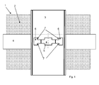
- the figure 1 shows an enlarged view of a preferred example of crimping according to the invention at the intersection of a rib (4) and a stiffener (3) seen from its inner face to the bottom of the U-shaped section.
- the perpendicularly crossing rib the stiffener is supported on the outer face of the U-shaped section.
- the stiffener (3) and the rib (4) comprise an orifice (5) traversed by tabs (6, 6 ') resulting from stamping performed at once. in the rib (4) and the stiffener.
- the tabs (6, 6 ') are bent, for example, on two opposite edges of the orifice (8) towards the inside of the U-shaped section as shown in FIG.
- the tabs (6) issuing from the rib (4) passing through the orifice (5).
- They each comprise a part of a given width (5.6 mm in one embodiment) whose end is attached to the rib (4), respectively to the stiffener (3) and a wider part (8 mm for example) having one end free.
- the contour of the junction of the narrow part and the wider part of a tongue (6, 6 ') forms two stops (7, 7') symmetrical preferably placed one facing the other. These stops (7, 7 ') have a contour preferably forming a right angle and are located at a predetermined distance from one end of the tongue (6, 6'), for example about 5 mm from the end free of the tongue (6, 6 '). Each abutment (7, 7 ') of width 1.2 mm in the example plays a role of locking the tongue (6) issuing from the rib (4) once bent over the edge (8) of the orifice (5).
- the width of the orifice (5) in the vicinity of the attached end of the tongue (6) is less than the width of said orifice (5) near its center. This difference in width constituting the abutments (7) makes it possible to prevent the tabs (6) issuing from the rib (4) from leaving the orifice (5) from being pressed against the mesh sheet (2).
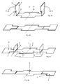
- the figure 2a shows a first crimping option in which the respective tabs (6, 6 ') issuing from the stiffener (3) and the rib (4) are bent substantially at right angles to the plane of the orifice (5).
- a crimp of this type has a clearance equivalent to the distance separating the attached end of the tongue (6) and the stops (7) (about 5 mm according to the example).
- Internal pressure P due to the filling concrete on the grid sheet (2) will advance the grid sheet (2) relative to the stiffeners (3) leaving a space equivalent to the clearance between the stiffeners (3) and the ribs (4) .
- This movement remains limited to the game thanks to the stops (7) of the tongues (6) which prevent the release of these out of their orifices (5) corresponding.
- play is reduced to a minimum.
- the tongues (6, 6 ') are folded against the internal face of the stiffener (3) at the bottom of the U-section using a suitable tool.
- the figure 2b shows a crimping in which the two tabs (6, 6 ') of the stiffener (3) and the rib (4) are folded symmetrically along their ends attached to the edge (8) of the orifice (5) so as to apply against the face of the stiffener (3) on two opposite sides of the orifice (5) (arrows R).
- This type of crimping provides better resistance of the mesh (2) on the stiffeners (3) leaving no clearance between the ribs (4) and the stiffeners (3) as presented in the first option.
- the Figure 2c shows the behavior of a crimped tab (6, 6 ') folded as shown in FIG. figure 2b when pressure forces P are exerted on the grid sheet (2).
- the pressure P causes the tongues (6) coming from the rib (4) to be straightened so as to form an angle close to 90 degrees with the plane of the orifice (5) or that of the internal face of the stiffener profile (3). ), the tabs (6 ') from the stiffener (3) remaining folded.
- the abutments (7) rest on the inner face of the stiffener (3) at the edge (8) of the narrow portion of the orifice (5) preventing the exit of the tongue (6).
- the stall removal problem (2) proper crimping tabs of constant width over their entire length as described in document W02007 / 079989 is thus solved by stops (7) acting as locking.
- figure 2d shows tabs each having a recess acting as a stop.
- the staggered arrangement of the recesses avoids a torsion effect of the rib at the crimping under the effect of pressure forces.
- the asymmetrical shape of the orifice (5) corresponds to the shape of each of the tongues.
- the preferred configuration of the crimping corresponds to that comprising symmetrical tongues with two recesses forming two abutments one facing each other as represented by the figures 1 , 2a, 2b and 2c .
- the advantage of the crimping is that it can be done quickly with a suitable machine tool allowing at first time to stamp the rib (4) and the stiffener (3) and in a second time fold respectively the tabs (6) of the rib (4) and the tongues (6 ') of the stiffener (3) in the orifice (5) of the stiffener (3).
- stamping and bending operations of the tongues (6, 6 ') are performed simultaneously when the ribs (4) and the stiffeners (3) are kept in their final position on the machine.
- the orifices (5) of the stiffeners (3) can be stamped during a preliminary stage. In this case, only the tabs (6) from the ribs are folded towards the inner face of the profile of the stiffener (3) during crimping.
- This variant requires a prior positioning of the stiffeners (3) and an alignment of the orifices (5) accurate with respect to the ribs (4) of the mesh (2) so as to stamp and fold the tongues (6) under optimal conditions.
- the invention also relates to a crimping tool of a plurality of stiffeners (3) to a grid sheet (2) having a plurality of ribs (4) forming a panel (1) formwork comprising a stamp (9) and a support (14) capable of forming an orifice (5) and two tabs (6) at an intersection between a rib (4) and a stiffener (3) having a first portion with an end attached to the rib (4) and a free end characterized in that the end of the die (9) forms a symmetrical tip with a central edge (12) and two pairs of lateral edges (13) inclined perpendicular to the central edge (12) and in that the section comprises a central portion of greater width than the width of the parts located on either side of the central part, said stamp (9) and said support (14) being able to create two opposite symmetrical tongues (6) having in the vicinity the end attached to the rib (4), a first portion of width less than the width of a second portion in the vicinity of the free end, the contour of the two parts
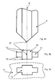
- the stamping of tabs (6, 6 ') and the orifice (5) as illustrated by the Figures 2a to 2c is performed with tools comprising a stamp (9) and a support (14) as represented by the Figures 3a to 3c .
- the section of the stamp (9) has a shape corresponding to that of the orifice (5) with a part near the center wider than the parts located on either side of said center.
- the end forms a tip with a central sharp edge (12) for creating the free ends of each tongue (6, 6 ').
- the cutting of the rest of the contour of the tongues (6) with the stops (7) is performed by two pairs of sharp edges (13) sideways inclined perpendicularly to each side of the central edge (12).
- the figure 3b shows a top view of the tip of the stamp (9) with the central ridge (12) passing through the wide part of the section.
- the stamp (9) first passes through the metal of the rib (4) then that of the stiffener (3) while cutting in a single operation the tongues (6, 6 ') and the orifice (5) both in the rib (4) and in the stiffener (3).
- the support (14) illustrated by the figure 3c having a window (15) similar to the orifice (5) created by the stamp (9) is placed against the inner face of the stiffener (3) facing the stamp (9) so as to slide it after having formed the tabs (6, 6 ') in the metal of the rib (4) and the stiffener (4).
- the window (15) of the support (14) has a depth dimensioned so as to position the tabs (6, 6 ') perpendicular to the plane of the window (15).
- the tabs (6, 6 ') are then folded against the inner face of the stiffener profile (3) with a suitable tool after removal of the stamp (9) and the support (14). .
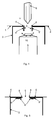
- the figure 4 shows a schematic form of a stamping tool (9) for making an orifice (5) both through the rib (4) and the stiffener (3) while forming tabs opposite to one another with respect to the other with each end attached to the edge (8) of the two opposite sides of the orifice (5) and a free end.
- the tongues (6, 6 ') directed towards the inner face of the stiffener profile (3) are folded against this face by means of a crimping tool (16) from the underside of the panel (1).
- a support portion of the not shown die acting after removal of the stamp presses the rib (4) on an area adjacent the orifice (5) to maintain the rib assembly (4) stiffener (3) when the folding tool (16) folds the tabs (6, 6 ').
- This tool (16) has a shaped end dimensioned and adapted to bend the tabs (6, 6 ') against the inner face of the stiffener (3) as illustrated by the figure 5 .
- the end of this tool (16) of folding can deviate as it advances to completely flatten the tabs (6, 6 ') against the stiffener (3).
- crimping according to the invention can be performed with a single tongue (6, 6 ') when for example the width of the U of the stiffener is insufficient to contain two tabs (6, 6') symmetrical opposite and folded down share and other of the orifice (5).
- the outline of the orifice (5) corresponds to the contour of a tongue (6) with two parts of different width as represented by the figures 1 , 2a, 2b and 2c considering only half left or right of the axis of symmetry A.
- the stamp (9) also adapted to form a tongue, has an asymmetrical tip whose shape corresponds to the left half or the half right with respect to the axis of symmetry A of the point represented by the Figures 3a and 3b .
- the window (15) of the support (14) naturally has a shape corresponding to one of the halves with respect to the axis A of the form illustrated by the figure 3c .
- the figure 6 illustrates an example of crimping with a single tongue (6, 6 ') per orifice (5).
- the stamping of the tongues (6, 6 ') is carried out so that they are retained alternately on the straight sides and left ports (5) aligned along the same rib (4).
- the tongues (6, 6 ') can also be alternately attached to the right and left sides of each orifice (5) along each stiffener (3). They thus have a staggered configuration on all the intersections between the ribs (4) and the stiffeners (3) of the panel (1)
- the manufacture of a panel (1) is performed by a machine on which the grid sheet (2) is held temporarily flat on stiffeners (3) by means of clamping devices.
- stamping and folding steps of the tongues (6, 6 ') are generally performed simultaneously on a plurality of intersections between at least one rib (4) and stiffeners (3) by a plurality of stamping tools. (9) and drawdown (16). These tools, aligned on at least one support parallel to the ribs (4) and arranged opposite said intersections advance along the interval between the ribs (4) in order to crimp the mesh sheet (2) at each crossing of the ribs (4) with the stiffeners (3).
- the present invention also relates to a formwork comprising two panels (1), as described above, placed facing each other and connected by connecting elements articulated to the panels by means of the stiffeners (3). .
- the wall erected with integrated formwork as described above is also an object of the present invention.
- the gap between the two panels (1) is filled with concrete or similar material.
- a concrete slab made with a panel (1) described above is also an object of the present invention.
- the slab is made by placing the panel (1) generally horizontally with the face having the stiffeners (3) directed upwards.
- Reinforcing reinforcements are generally placed on the stiffeners before pouring a layer of concrete preferably uniform on this face.
- the quantity of reinforcement and the thickness of the concrete layer are determined according to the slab range, the loads, the concrete quality, etc.
Landscapes
- Engineering & Computer Science (AREA)
- Architecture (AREA)
- Civil Engineering (AREA)
- Structural Engineering (AREA)
- Mechanical Engineering (AREA)
- Physics & Mathematics (AREA)
- Electromagnetism (AREA)
- Forms Removed On Construction Sites Or Auxiliary Members Thereof (AREA)
Priority Applications (5)
| Application Number | Priority Date | Filing Date | Title |
|---|---|---|---|
| EP09150171A EP2206847A1 (de) | 2009-01-07 | 2009-01-07 | Schalungsplatte mit gesicherter Bördelung |
| RU2011130251/03A RU2011130251A (ru) | 2009-01-07 | 2010-01-06 | Панель для опалубки с креплением отгибкой |
| PCT/EP2010/050084 WO2010079186A1 (en) | 2009-01-07 | 2010-01-06 | Panel for formwork with secured crimping |
| EP10700021A EP2386006A1 (de) | 2009-01-07 | 2010-01-06 | Platte für schalung mit gesicherter crimpung |
| CN2010800040742A CN102272392A (zh) | 2009-01-07 | 2010-01-06 | 用于具有紧固卷曲的模板的嵌板 |
Applications Claiming Priority (1)
| Application Number | Priority Date | Filing Date | Title |
|---|---|---|---|
| EP09150171A EP2206847A1 (de) | 2009-01-07 | 2009-01-07 | Schalungsplatte mit gesicherter Bördelung |
Publications (1)
| Publication Number | Publication Date |
|---|---|
| EP2206847A1 true EP2206847A1 (de) | 2010-07-14 |
Family
ID=40637923
Family Applications (2)
| Application Number | Title | Priority Date | Filing Date |
|---|---|---|---|
| EP09150171A Withdrawn EP2206847A1 (de) | 2009-01-07 | 2009-01-07 | Schalungsplatte mit gesicherter Bördelung |
| EP10700021A Withdrawn EP2386006A1 (de) | 2009-01-07 | 2010-01-06 | Platte für schalung mit gesicherter crimpung |
Family Applications After (1)
| Application Number | Title | Priority Date | Filing Date |
|---|---|---|---|
| EP10700021A Withdrawn EP2386006A1 (de) | 2009-01-07 | 2010-01-06 | Platte für schalung mit gesicherter crimpung |
Country Status (4)
| Country | Link |
|---|---|
| EP (2) | EP2206847A1 (de) |
| CN (1) | CN102272392A (de) |
| RU (1) | RU2011130251A (de) |
| WO (1) | WO2010079186A1 (de) |
Families Citing this family (1)
| Publication number | Priority date | Publication date | Assignee | Title |
|---|---|---|---|---|
| CN111366530B (zh) * | 2020-03-26 | 2023-10-27 | 马鞍山十七冶工程科技有限责任公司 | 一种现场粘结拉拔检测试验粘结板固定装置 |
Citations (5)
| Publication number | Priority date | Publication date | Assignee | Title |
|---|---|---|---|---|
| FR2497857A1 (fr) | 1981-01-13 | 1982-07-16 | Atlas Maisons | Panneau prefabrique et profiles pour la realisation de ce panneau |
| FR2712016A1 (fr) | 1993-11-02 | 1995-05-12 | Coffratherm Ste Civile Invente | Procédé de fabrication de parois de coffrage pour bâtiment et chaîne de fabrication s'y rapportant. |
| WO2005042864A1 (fr) | 2003-11-03 | 2005-05-12 | Polyfinance Coffor Holding S.A. | Coffrage à résistance élevée pour mur en béton |
| WO2007079989A1 (fr) | 2006-01-12 | 2007-07-19 | Polyfinance Coffor Holding S.A. | Panneau pour coffrage |
| WO2008041024A1 (en) * | 2006-10-04 | 2008-04-10 | Expamet Building Products Limited | Formwork system |
Family Cites Families (1)
| Publication number | Priority date | Publication date | Assignee | Title |
|---|---|---|---|---|
| CN2658251Y (zh) * | 2003-11-03 | 2004-11-24 | 杨爱华 | 一种免拆除建筑模网 |
-
2009
- 2009-01-07 EP EP09150171A patent/EP2206847A1/de not_active Withdrawn
-
2010
- 2010-01-06 EP EP10700021A patent/EP2386006A1/de not_active Withdrawn
- 2010-01-06 RU RU2011130251/03A patent/RU2011130251A/ru not_active Application Discontinuation
- 2010-01-06 WO PCT/EP2010/050084 patent/WO2010079186A1/en not_active Ceased
- 2010-01-06 CN CN2010800040742A patent/CN102272392A/zh active Pending
Patent Citations (5)
| Publication number | Priority date | Publication date | Assignee | Title |
|---|---|---|---|---|
| FR2497857A1 (fr) | 1981-01-13 | 1982-07-16 | Atlas Maisons | Panneau prefabrique et profiles pour la realisation de ce panneau |
| FR2712016A1 (fr) | 1993-11-02 | 1995-05-12 | Coffratherm Ste Civile Invente | Procédé de fabrication de parois de coffrage pour bâtiment et chaîne de fabrication s'y rapportant. |
| WO2005042864A1 (fr) | 2003-11-03 | 2005-05-12 | Polyfinance Coffor Holding S.A. | Coffrage à résistance élevée pour mur en béton |
| WO2007079989A1 (fr) | 2006-01-12 | 2007-07-19 | Polyfinance Coffor Holding S.A. | Panneau pour coffrage |
| WO2008041024A1 (en) * | 2006-10-04 | 2008-04-10 | Expamet Building Products Limited | Formwork system |
Also Published As
| Publication number | Publication date |
|---|---|
| CN102272392A (zh) | 2011-12-07 |
| WO2010079186A1 (en) | 2010-07-15 |
| EP2386006A1 (de) | 2011-11-16 |
| RU2011130251A (ru) | 2013-02-20 |
Similar Documents
| Publication | Publication Date | Title |
|---|---|---|
| EP1644592B1 (de) | Schalung mit erhöhtem widerstand für betonwand | |
| EP1756367B1 (de) | Leichte metallfuge für betonflächen | |
| EP2211000B1 (de) | Schaltafel für eine Betonmauer | |
| FR2481248A1 (fr) | Elements de fleche legers et resistants pour fleche de grue telescopique et fleche de grue formee de tels elements | |
| BE679420A (de) | ||
| EP2674538B1 (de) | Modulkonstruktion und entsprechendes Verfahren zum Zusammenbau | |
| CA2252007A1 (fr) | Paroi ou enveloppe formee de feuilles de tole tendues sur une ossature ou une charpente et son procede de construction | |
| EP0568441A1 (de) | Tragstruktur wie zum Beispiel eine Decke, mit Trägern und einer Betonplatte und Verfahren zu ihrer Herstellung | |
| EP3428109A1 (de) | Dynamischer und evolutiver hubanker für ein bauelement, insbesondere mit geringer dicke, multikonfigurationen und multikräften | |
| WO2007079989A1 (fr) | Panneau pour coffrage | |
| EP3263794A1 (de) | Paneel für verschalung | |
| EP3221207B1 (de) | Anordnung zur verstärkung von einsätzen aus einem polymermaterial mit trennbaren verstärkungseinsätzen | |
| BE1017376A5 (fr) | Joint metallique permettant la dilatation entre dalles de beton. | |
| EP1749951B1 (de) | Verlorenes Schalungselement und Module zur Herstellung eines solchen Elements | |
| EP1176086A1 (de) | Rahmen mit einer reduzierten Anzahl von Schweissnähten, Langsträger für einen solchen Rahmen, und dessen Herstellungsverfahren | |
| FR3036419A1 (fr) | Poutrelle de ferraillage pour coffrage de mur de piscine | |
| EP2722458B1 (de) | Dachrinne | |
| WO2021239644A1 (fr) | Element d'armatures pour paroi moulee muni d'un porte-joint d'etancheite | |
| EP1678389B1 (de) | Selbsttragende stahlschalung mit grosser spannweite | |
| FR2893058A1 (fr) | Dispositif pour faciliter le coffrage rapide et le montage de murs, dalles, planchers et similaires | |
| EP4343079B1 (de) | Wandverbindungsbeschlag mit integrierter schalung | |
| FR2878877A1 (fr) | Bloc de coffrage | |
| FR2998314A1 (fr) | Dispositif de maintien des fers de renfort dans une structure de banchage d'une paroi | |
| WO2013164519A1 (fr) | Coffrage et plancher associé | |
| FR2962066A1 (fr) | Procede de fabrication d'un element structurel en beton et element structurel prefabrique en beton. |
Legal Events
| Date | Code | Title | Description |
|---|---|---|---|
| PUAI | Public reference made under article 153(3) epc to a published international application that has entered the european phase |
Free format text: ORIGINAL CODE: 0009012 |
|
| AK | Designated contracting states |
Kind code of ref document: A1 Designated state(s): AT BE BG CH CY CZ DE DK EE ES FI FR GB GR HR HU IE IS IT LI LT LU LV MC MK MT NL NO PL PT RO SE SI SK TR |
|
| AX | Request for extension of the european patent |
Extension state: AL BA RS |
|
| AKY | No designation fees paid | ||
| REG | Reference to a national code |
Ref country code: DE Ref legal event code: R108 Effective date: 20110222 Ref country code: DE Ref legal event code: 8566 |
|
| STAA | Information on the status of an ep patent application or granted ep patent |
Free format text: STATUS: THE APPLICATION IS DEEMED TO BE WITHDRAWN |
|
| 18D | Application deemed to be withdrawn |
Effective date: 20110115 |