EP2206854A2 - Clapet de révision - Google Patents
Clapet de révision Download PDFInfo
- Publication number
- EP2206854A2 EP2206854A2 EP09014715A EP09014715A EP2206854A2 EP 2206854 A2 EP2206854 A2 EP 2206854A2 EP 09014715 A EP09014715 A EP 09014715A EP 09014715 A EP09014715 A EP 09014715A EP 2206854 A2 EP2206854 A2 EP 2206854A2
- Authority
- EP
- European Patent Office
- Prior art keywords
- closure
- corner
- cam
- flap
- foot
- Prior art date
- Legal status (The legal status is an assumption and is not a legal conclusion. Google has not performed a legal analysis and makes no representation as to the accuracy of the status listed.)
- Withdrawn
Links
- 238000007689 inspection Methods 0.000 claims description 11
- 230000002787 reinforcement Effects 0.000 claims description 3
- 230000008719 thickening Effects 0.000 description 4
- 238000004519 manufacturing process Methods 0.000 description 3
- 206010053648 Vascular occlusion Diseases 0.000 description 2
- 210000003746 feather Anatomy 0.000 description 2
- 239000000463 material Substances 0.000 description 2
- 239000002184 metal Substances 0.000 description 2
- 238000004378 air conditioning Methods 0.000 description 1
- 230000000295 complement effect Effects 0.000 description 1
- 238000005516 engineering process Methods 0.000 description 1
- 230000003993 interaction Effects 0.000 description 1
- 230000008092 positive effect Effects 0.000 description 1
Images


Classifications
-
- E—FIXED CONSTRUCTIONS
- E04—BUILDING
- E04F—FINISHING WORK ON BUILDINGS, e.g. STAIRS, FLOORS
- E04F19/00—Other details of constructional parts for finishing work on buildings
- E04F19/08—Built-in cupboards; Masks of niches; Covers of holes enabling access to installations
- E04F19/083—Covers with fixing means providing for snap locking
-
- E—FIXED CONSTRUCTIONS
- E05—LOCKS; KEYS; WINDOW OR DOOR FITTINGS; SAFES
- E05C—BOLTS OR FASTENING DEVICES FOR WINGS, SPECIALLY FOR DOORS OR WINDOWS
- E05C19/00—Other devices specially designed for securing wings, e.g. with suction cups
- E05C19/02—Automatic catches, i.e. released by pull or pressure on the wing
- E05C19/022—Released by pushing in the closing direction
-
- E—FIXED CONSTRUCTIONS
- E05—LOCKS; KEYS; WINDOW OR DOOR FITTINGS; SAFES
- E05B—LOCKS; ACCESSORIES THEREFOR; HANDCUFFS
- E05B65/00—Locks or fastenings for special use
- E05B65/006—Locks or fastenings for special use for covers or panels
Definitions
- the present invention relates to an inspection flap for a manhole or a wall or a ceiling with a frame having corner reinforcements. Furthermore, the present invention relates to a closure for a revision flap.
- Inspection flaps are well-known to those skilled in the art and are used to inspect cavities behind walls or shafts or ceilings, which are required for example for air conditioning and / or cable or wiring in buildings. Such inspection flaps are usually provided at one end with a hinge and have at the opposite end a closure with which the access panel can be reversibly held in a closed state on the wall or the shaft or the ceiling.
- the known from the prior art inspection flaps are constructed comparatively complicated and designed comparatively expensive.
- the object is achieved with an access door for a shaft or a wall or a ceiling, with a frame having corner amplifier, wherein at least one corner amplifier is the storage of a closure on the access door or the wall / bay.
- the present invention relates to an access door for a manhole or a wall or a ceiling.
- This inspection flap has a frame, which is usually composed of four pieces, in particular metal pieces. In the corners of these pieces of metal are each provided with a corner amplifier to give the frame greater stability and / or to arrange the frame pieces on the access panel. According to the corner amplifier is now also the storage for the closure on the access panel.
- This embodiment of the invention has the advantage that the closure does not have to be stored separately on the inspection flap.
- the Closure can be mounted simultaneously with the corner amplifier on the access panel. This results in a saving of material on the one hand and on the other hand also a saving in the required work steps.
- the closure is floatingly mounted on the access door, d. H. it is attached to a certain extent movable on the access panel.
- This preferred embodiment of the present invention has the advantage that larger tolerances can be tolerated in the production, because by the floating bearing of the closure automatically finds its counterpart and can interact with this locking.
- the corner amplifier has an up and / or a recess which at least partially receives the foot of the closure and thereby constitutes a bearing for the foot and thus for the closure.
- the corner reinforcement on a form and / or adhesion means which fixes the shutter at least partially in its position.
- the closure cooperates with a counterpart located on the well and / or on the wall or on the ceiling.
- this counterpart is also floating in order to facilitate or ensure the interaction of closure and counterpart even at high manufacturing tolerances.
- the closure can also be arranged on the shaft or the wall or on the ceiling and the counterpart on the flap.
- Another object of the present invention is a closure of a revision flap with a main body in which a cam is rotatably mounted and on which a slide is arranged longitudinally displaceable, wherein the cam alternately end and locking cooperates with the slider and the ratio of length to width the cam is 0.6 - 0.7.
- the closure is also finished with very small dimensions bar, which in particular has a positive effect on the material consumption and / or on the weight of the access door.
- the cam disk in the corner region has a radius particularly preferably ⁇ 3 mm, very particularly preferably 5 5 mm.
- FIG. 1 shows the access door 1 according to the invention, which has a frame 4.
- This frame 4 consists of at least two parts which are connected to each other in the corner by a corner connector 6.
- the frame parts 4 can themselves be connected to the access door 1, for example, glued, or be attached to the access door 1 via the corner connectors 6.
- the corner connector 6 and thus the frame parts 4 are arranged with clinch points 8 on the access door.
- a Movement limiter 5 is arranged, which prevents the access door opens uncontrollably after release of the closure.
- the corner connector 6 is also the storage for the shutter 9 at the same time.
- the closure 9 cooperates with a counterpart 10, which in particular has a displaceably mounted bearing plate 11 which cooperates lockingly with the closure.
- the counterpart 10, in the present case an angle, is provided integrally with a corner connector 7 which connects the frame parts 3 provided on the wall or on the shaft or on the ceiling.
- the corner connector 7 is also provided with clinching points 8 on the wall or on the shaft or on the ceiling.
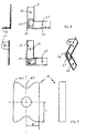
- FIG. 2 shows a first embodiment of the corner connector 6.
- This has two holes 6.3, which serve to accommodate the tool.
- the corner connector on a tab 6.6, on which the ⁇ réellesbegrenzer 5 is mounted.
- a receptacle 6.4 is embossed, which receives the foot of the shutter 9 at least partially.
- the corner connector 6 has a recess, in this case a bore 6.5, through which the main body 12 of the closure 9 is guided.
- Both the receptacle 6.4 and the recess 6.5 are at least partially designed in their dimensions that the shutter 9 is floatingly mounted on the access door, so that it can move within certain limits even after the attachment of the corner connector on the access panel. As a result, manufacturing tolerances can be relatively generously allowed, because the closure can align itself appropriately to the counterpart.
- FIG. 3 shows a further embodiment of the corner connector 6.
- the corner connector 6 positive locking means 6.1 and 6.2, with complementary MitNotmittein 13.1, 13.2 (see. FIG. 5 ) and fix the closure 9 in at least two directions in its position.
- the person skilled in the art understands that the thickening 6.2 only has to be present if in Longitudinal direction of the web 6.2 no stop is provided. At the in FIG. 3 illustrated embodiment, the thickening 6.2 is not necessarily needed.
- the embodiment of the corner connector 6 shown here is particularly suitable for frame parts which have a groove on the right and left, which receive the edge of the corner connector and also the edge of the foot 13 of the closure 9. The skilled artisan will recognize that the embodiment according to FIG. 3 for a floating storage is not or only partially suitable.
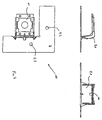
- FIG. 4 shows the counterpart 10 of the closure 9.
- This counterpart 10 is in the present case an angle which is arranged on the corner connector 7, the two frame parts 3, which are arranged on the shaft or the wall or on the ceiling, interconnected.
- a bearing plate is slidably mounted, so that even here find the connection between the shutter 9 and the bearing plate 11 is facilitated.
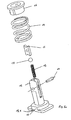
- FIGS. 5a and 5b show the closure according to the invention.
- This has a foot 13, which is at least partially enclosed by the corner connector and / or cooperates positively with the corner connector.
- the foot 13 the positive locking means 13.1 and 13.2.
- the lower plate of the foot 13 is provided, which is at least partially enclosed by the corner connector.
- the cam 16 is mounted at the foot 13 of the main body 12 on the rotatably by means of a deformation pin 17, the cam 16 is mounted. against this cam presses in the lower part of a ball 18 which is biased by a spring 19 against the cam 16.
- the cam 16 acts with a slide 15, which is provided longitudinally displaceably on the main body 12 alternately latching and unlocking together.
- the slider 15 cooperates with a spring 14.
- the slider 15 is locked in a lowered position by the cam, in which it is inclined.
- the slide is unlocked and moved by the spring 14 to a raised position with the longitudinal axis of the cam being aligned parallel to the longitudinal axis of the main body,
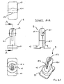
- FIG. 5b shows details of the foot 13 and in particular of the main body 12.
- This has a bore 12.1, which receives the dowel pin 17 by clamping.
- the cam plate 16 (not shown) is rotatably mounted.
- the cam 16 is arranged in the slot 12.2.
- the main body 12 has a recess, here a bore 12.3, in which the spring 19 is arranged.
- a guide for the ball 18 is present.
- At the bottom of the foot of the closure according to the invention has two positive locking means 13.1 and 13.2, which can cooperate positively with the respective corner connector (see. Fig. 3 ).
- FIG. 6 shows the cam of the closure according to the invention in two views.
- the corner regions 16.1 of the cam of the closure according to the invention are rounded in the present case, preferably with a radius ⁇ 0.3 mm, very particularly preferably with a radius ⁇ 5 mm.
- the cam has a hooking region 16.2, in which the ball 18 statically uniquely determined rests or cooperating locking with the closure 15.
- the cam is mirror-symmetrical with respect to both central axes. By the ratio of the width B to the length L of 0.6 to 0.7, it is possible to make very compact closures that work clearly.
Landscapes
- Engineering & Computer Science (AREA)
- Architecture (AREA)
- Civil Engineering (AREA)
- Structural Engineering (AREA)
- Mechanical Engineering (AREA)
- Connector Housings Or Holding Contact Members (AREA)
- Buffer Packaging (AREA)
- Hinges (AREA)
Applications Claiming Priority (1)
| Application Number | Priority Date | Filing Date | Title |
|---|---|---|---|
| DE202008016931U DE202008016931U1 (de) | 2008-12-23 | 2008-12-23 | Revisionsklappe |
Publications (2)
| Publication Number | Publication Date |
|---|---|
| EP2206854A2 true EP2206854A2 (fr) | 2010-07-14 |
| EP2206854A3 EP2206854A3 (fr) | 2012-03-07 |
Family
ID=40690409
Family Applications (1)
| Application Number | Title | Priority Date | Filing Date |
|---|---|---|---|
| EP09014715A Withdrawn EP2206854A3 (fr) | 2008-12-23 | 2009-11-26 | Clapet de révision |
Country Status (2)
| Country | Link |
|---|---|
| EP (1) | EP2206854A3 (fr) |
| DE (1) | DE202008016931U1 (fr) |
Cited By (1)
| Publication number | Priority date | Publication date | Assignee | Title |
|---|---|---|---|---|
| EP2677099A3 (fr) * | 2012-06-18 | 2016-01-20 | Düperthal Sicherheitstechnik GmbH & Co.KG | Armoire de sécurité |
Families Citing this family (3)
| Publication number | Priority date | Publication date | Assignee | Title |
|---|---|---|---|---|
| DE202011001347U1 (de) | 2011-01-11 | 2011-06-01 | Riegelhof & Gärtner GmbH, 64331 | Verschluss und Rastmittel insbesondere für eine Revisionsklappe |
| CN105386586A (zh) * | 2015-12-15 | 2016-03-09 | 山东霞光实业有限公司 | 一种踢脚线 |
| CA3064662A1 (fr) * | 2017-07-20 | 2019-01-24 | Knauf Gips Kg | Dispositif de fermeture, de preference pour fermer un volet d'etancheite d'une ouverture |
Citations (1)
| Publication number | Priority date | Publication date | Assignee | Title |
|---|---|---|---|---|
| EP1516979A1 (fr) * | 2003-09-19 | 2005-03-23 | Günter Dipl.-Ing. Langenhorst | Porte de visite |
Family Cites Families (2)
| Publication number | Priority date | Publication date | Assignee | Title |
|---|---|---|---|---|
| DE20102563U1 (de) * | 2001-02-14 | 2001-06-28 | Riegelhof & Gärtner oHG, 64331 Weiterstadt | Abdeckvorrichtung für Revisionsöffnungen |
| DE102004040175A1 (de) * | 2004-08-18 | 2006-03-02 | Riegelhof & Gärtner oHG | Komponente für ein Schloss, Schloss zum Verbinden eines ersten Bauteils mit einem zweiten Bauteil und Verwendung des Schlosses |
-
2008
- 2008-12-23 DE DE202008016931U patent/DE202008016931U1/de not_active Expired - Lifetime
-
2009
- 2009-11-26 EP EP09014715A patent/EP2206854A3/fr not_active Withdrawn
Patent Citations (1)
| Publication number | Priority date | Publication date | Assignee | Title |
|---|---|---|---|---|
| EP1516979A1 (fr) * | 2003-09-19 | 2005-03-23 | Günter Dipl.-Ing. Langenhorst | Porte de visite |
Cited By (1)
| Publication number | Priority date | Publication date | Assignee | Title |
|---|---|---|---|---|
| EP2677099A3 (fr) * | 2012-06-18 | 2016-01-20 | Düperthal Sicherheitstechnik GmbH & Co.KG | Armoire de sécurité |
Also Published As
| Publication number | Publication date |
|---|---|
| DE202008016931U1 (de) | 2009-05-20 |
| EP2206854A3 (fr) | 2012-03-07 |
Similar Documents
| Publication | Publication Date | Title |
|---|---|---|
| DE102006024184A1 (de) | Verbindung für Plattenpaneele | |
| EP3622149B1 (fr) | Rail de guidage d'un chariot d'une porte de meuble | |
| CH696889A5 (de) | Verriegelungselement und Verfahren zur Verriegelung von zwei Platten. | |
| DE102009056766B4 (de) | Puzzlespiel mit einem oder mehreren knickbaren Puzzleteilen | |
| DE102011108895A1 (de) | Tragende Struktur für bewegliches Staufach | |
| EP4077848A1 (fr) | Appareil de guidage servant à guider une partie d'un meuble | |
| DE202022002815U1 (de) | Verbesserte Inspektionsklappe | |
| EP2992225B1 (fr) | Moyen de liaison | |
| DE202006021264U1 (de) | Tür- und Fensterrahmen mit einem hinterschnittenen Eingriffsbereich für eine Getriebeeinheit | |
| EP2206854A2 (fr) | Clapet de révision | |
| DE10361445B4 (de) | Kraftfahrzeugtürschloss | |
| DE202019005719U1 (de) | Regalsystem und Ablagefächer für Regalsysteme | |
| AT523303B1 (de) | Führungsvorrichtung zur Führung eines Möbelteils | |
| DE102004031466B4 (de) | Vorrichtung zur Aufnahme von Gütern | |
| EP2487058B1 (fr) | Couvercle pour un système de toit coulissant | |
| EP3636104A2 (fr) | Dispositif d'accouplement pour le guidage de coulisse | |
| EP2634063B1 (fr) | Porte coulissante d'un véhicule sur rail | |
| DE10313842B4 (de) | Schranktür | |
| DE102016004915B3 (de) | Beschlag für ein Fenster, Verfahren zum Herstellen des Beschlags sowie entsprechendes Fenster | |
| DE102007006735A1 (de) | Kraftfahrzeugtür mit Innengriffanordnung | |
| AT523374B1 (de) | Verbindungsvorrichtung, insbesondere Scharnier | |
| EP2597997A1 (fr) | Elément mobile et disposition d'un élément mobile dans un meuble | |
| DE202008010542U1 (de) | Profilleistenvorrichtung | |
| DE102006047238A1 (de) | Stelleinrichtung zum Ausrichten von Lagerteilen an toleranzbehafteten Strukturen | |
| EP4047224A1 (fr) | Élément de raccordement |
Legal Events
| Date | Code | Title | Description |
|---|---|---|---|
| PUAI | Public reference made under article 153(3) epc to a published international application that has entered the european phase |
Free format text: ORIGINAL CODE: 0009012 |
|
| AK | Designated contracting states |
Kind code of ref document: A2 Designated state(s): AT BE BG CH CY CZ DE DK EE ES FI FR GB GR HR HU IE IS IT LI LT LU LV MC MK MT NL NO PL PT RO SE SI SK SM TR |
|
| AX | Request for extension of the european patent |
Extension state: AL BA RS |
|
| PUAL | Search report despatched |
Free format text: ORIGINAL CODE: 0009013 |
|
| AK | Designated contracting states |
Kind code of ref document: A3 Designated state(s): AT BE BG CH CY CZ DE DK EE ES FI FR GB GR HR HU IE IS IT LI LT LU LV MC MK MT NL NO PL PT RO SE SI SK SM TR |
|
| AX | Request for extension of the european patent |
Extension state: AL BA RS |
|
| RIC1 | Information provided on ipc code assigned before grant |
Ipc: E05C 19/02 20060101ALN20120203BHEP Ipc: E04F 19/08 20060101AFI20120203BHEP |
|
| TPAC | Observations filed by third parties |
Free format text: ORIGINAL CODE: EPIDOSNTIPA |
|
| 17P | Request for examination filed |
Effective date: 20120906 |
|
| 17Q | First examination report despatched |
Effective date: 20130226 |
|
| 19U | Interruption of proceedings before grant |
Effective date: 20120401 |
|
| 19W | Proceedings resumed before grant after interruption of proceedings |
Effective date: 20130902 |
|
| RAP1 | Party data changed (applicant data changed or rights of an application transferred) |
Owner name: RUG SEMIN GMBH |
|
| STAA | Information on the status of an ep patent application or granted ep patent |
Free format text: STATUS: THE APPLICATION IS DEEMED TO BE WITHDRAWN |
|
| 18D | Application deemed to be withdrawn |
Effective date: 20150601 |