EP2206878A2 - Multi-position hydraulic actuator - Google Patents
Multi-position hydraulic actuator Download PDFInfo
- Publication number
- EP2206878A2 EP2206878A2 EP10150651A EP10150651A EP2206878A2 EP 2206878 A2 EP2206878 A2 EP 2206878A2 EP 10150651 A EP10150651 A EP 10150651A EP 10150651 A EP10150651 A EP 10150651A EP 2206878 A2 EP2206878 A2 EP 2206878A2
- Authority
- EP
- European Patent Office
- Prior art keywords
- piston
- chamber
- pressure source
- actuator
- communication
- Prior art date
- Legal status (The legal status is an assumption and is not a legal conclusion. Google has not performed a legal analysis and makes no representation as to the accuracy of the status listed.)
- Withdrawn
Links
- 238000004891 communication Methods 0.000 claims abstract description 70
- 238000000034 method Methods 0.000 claims abstract description 14
- 238000006073 displacement reaction Methods 0.000 claims description 6
- 238000013461 design Methods 0.000 description 5
- 230000008901 benefit Effects 0.000 description 3
- 239000012530 fluid Substances 0.000 description 3
- 230000002706 hydrostatic effect Effects 0.000 description 3
- 238000012360 testing method Methods 0.000 description 3
- 230000015572 biosynthetic process Effects 0.000 description 2
- 238000010586 diagram Methods 0.000 description 2
- 239000007789 gas Substances 0.000 description 2
- 238000012856 packing Methods 0.000 description 2
- 238000007792 addition Methods 0.000 description 1
- 238000012217 deletion Methods 0.000 description 1
- 230000037430 deletion Effects 0.000 description 1
- 238000012986 modification Methods 0.000 description 1
- 230000004048 modification Effects 0.000 description 1
- 238000003825 pressing Methods 0.000 description 1
- 239000007787 solid Substances 0.000 description 1
- 238000006467 substitution reaction Methods 0.000 description 1
Images



Classifications
-
- E—FIXED CONSTRUCTIONS
- E21—EARTH OR ROCK DRILLING; MINING
- E21B—EARTH OR ROCK DRILLING; OBTAINING OIL, GAS, WATER, SOLUBLE OR MELTABLE MATERIALS OR A SLURRY OF MINERALS FROM WELLS
- E21B23/00—Apparatus for displacing, setting, locking, releasing or removing tools, packers or the like in boreholes or wells
- E21B23/04—Apparatus for displacing, setting, locking, releasing or removing tools, packers or the like in boreholes or wells operated by fluid means, e.g. actuated by explosion
- E21B23/0412—Apparatus for displacing, setting, locking, releasing or removing tools, packers or the like in boreholes or wells operated by fluid means, e.g. actuated by explosion characterised by pressure chambers, e.g. vacuum chambers
-
- E—FIXED CONSTRUCTIONS
- E21—EARTH OR ROCK DRILLING; MINING
- E21B—EARTH OR ROCK DRILLING; OBTAINING OIL, GAS, WATER, SOLUBLE OR MELTABLE MATERIALS OR A SLURRY OF MINERALS FROM WELLS
- E21B23/00—Apparatus for displacing, setting, locking, releasing or removing tools, packers or the like in boreholes or wells
- E21B23/04—Apparatus for displacing, setting, locking, releasing or removing tools, packers or the like in boreholes or wells operated by fluid means, e.g. actuated by explosion
- E21B23/042—Apparatus for displacing, setting, locking, releasing or removing tools, packers or the like in boreholes or wells operated by fluid means, e.g. actuated by explosion using a single piston or multiple mechanically interconnected pistons
Definitions
- the present disclosure relates generally to equipment utilized and operations performed in conjunction with a subterranean well and, in an embodiment described herein, more particularly provides a multi-position hydraulic actuator.
- actuators for operating downhole well tools include a piston which is displaced back and forth between two positions in response to differential pressure applied to the piston in alternating directions.
- a valve can be opened by displacing the piston in one direction, and the valve can be closed by displacing the piston in an opposite direction.
- actuators and associated methods are provided which solve at least one problem in the art.
- At least three positions of an actuator are achieved by manipulating pressure in only two lines connected to the actuator.
- Another example is described below in which multiple well tools are actuated using a single actuator with multiple positions.
- a method of actuating at least one well tool utilizing relatively high and low pressure sources includes the steps of: placing a chamber of an actuator for the well tool in communication with the high pressure source, thereby displacing a piston from a first position to a second position; and then placing another chamber of the actuator in communication with the low pressure source, thereby displacing the piston from the second position to a third position.
- the disclosure provides a multi-position actuator for actuating at least one well tool utilizing relatively high and low pressure sources.
- the actuator includes multiple chambers in the actuator, and an operating member which displaces to operate the well tool.
- a first position of the operating member corresponds to the low pressure source being in communication with the first chamber and the high pressure source being in communication with the second chamber, a second position of the operating member corresponds to the high pressure source being in communication with both of the chambers, and a third position of the operating member corresponds to the high pressure source being in communication with the first chamber and the low pressure source being in communication with the second chamber.
- a multi-position actuator for actuating at least one well tool utilizing relatively high and low pressure sources.
- the actuator includes multiple chambers in the actuator, and a piston which displaces an operating member to operate the well tool.
- the piston has a first position in the actuator corresponding to the low pressure source being in communication with the first chamber and the high pressure source being in communication with the second chamber.
- the piston has a second position in the actuator corresponding to the high pressure source being in communication with both of the chambers.
- the piston has a third position in the actuator corresponding to the high pressure source being in communication with the first chamber and the low pressure source being in communication with the second chamber.
- first and second pistons are exposed to the second pressure source at each of the first, second and third positions of the first piston.
- the first piston has a third surface area exposed to a lower pressure relative to the first pressure source
- the second piston has a fourth surface area exposed to the lower pressure relative to the first pressure source
- the fourth surface area is greater than the third surface area.
- the first piston has a fifth surface area exposed to the first pressure source
- the second piston has a sixth surface area exposed to the first pressure source
- a difference between the first and fifth surface areas on the first piston is less than a difference between the second and sixth surface areas on the second piston.
- FIG. 1 Representatively illustrated in FIG. 1 is a well system 10 which embodies principles of the present disclosure.
- a drill stem test is performed utilizing, in part, well tools 44, 46 for controlling flow between an interior flow passage 48 of a tubular string 50, an annulus 52 formed between the tubular string and a wellbore 54, and a formation 56 intersected by the wellbore.
- the wellbore 54 could be cased, as depicted in FIG. 1 , or it could be uncased.
- An actuator control system 12 is interconnected in the tubular string 50.
- the control system 12 is used to control operation of an actuator 18 for the well tools 44, 46 during the drill stem test.
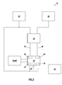
- the control system 12 may be of conventional design and so is not described further herein, but a schematic control valve 14 which may be used to control operation of the well tools 44, 46 via the actuator 18 is depicted in FIG. 2 .
- a control system for controlling operation of the well tools 44, 46 could be as described in the U.S. patent application filed concurrently herewith, entitled MODULAR ELECTRO-HYDRAULIC CONTROLLER FOR WELL TOOL, attorney docket no. 2008-IP-016830 U1 US, the entire disclosure of which is incorporated herein by this reference.
- the control system 12 controls operation of the actuators by selectively applying pressure to pistons of the actuator 18.
- the tubular string 50 may also include pressure sources 20, 22.
- a relatively low pressure source could be an atmospheric chamber or a low pressure side of a pump.
- a relatively high pressure source could be a pressurized gas chamber, hydrostatic pressure in the well, or a high pressure side of a pump. Any type of pressure source could be used, and it is not necessary for any of the pressure sources to be interconnected in the tubular string 50, in keeping with the principles of this disclosure.
- the annulus 52 or passage 48 could serve as the pressure source.
- the well tool 44 is depicted in FIG. 1 as being a circulating valve, and the well tool 46 is depicted as being a tester valve. However, actuation of any other type or combination of well tools could be controlled using the control system 12.
- the well system 10 is merely one example of an application of the principles of this disclosure. It is not necessary for a drill stem test to be performed, for the control system 12 to be interconnected in the tubular string 50, for fluid communication between the formation 56, passage 48 and annulus 52 to be controlled, or for well tools 44, 46 to be actuated.
- the principles of this disclosure are not limited in any manner to the details of the well system 10.
- FIG. 2 a schematic hydraulic circuit diagram of the control system 12 is representatively illustrated apart from the well system 10.
- a control valve 14 of the control system 12 is interconnected between the pressure sources 20, 22 and respective first and second chambers 24, 26 in the actuator 18.
- another pressure source 16 is shown as being in continuous communication with a third chamber 28, and the pressure source 20 is in continuous fluid communication with fourth and fifth chambers 30, 32 of the actuator.
- operation of the actuator 18 can be controlled by directing the pressures of the pressure sources 20, 22 to the first and second chambers 24, 26 via only two lines 34, 36 extending between the control valve 14 and the actuator 18.
- the pressure source 16 is preferably merely a low pressure in the chamber 28.
- the chamber 28 may be a sealed chamber at atmospheric pressure (or another relatively low pressure), without connecting a separate pressure source 16 to the chamber.
- the chamber 28 could be in communication with the low pressure source 22, in which case the pressure source 16 would correspond to the pressure source 22.
- the first pressure source 20 will be described as a high pressure source, and the second pressure source 22 will be described as a low pressure source.
- the first pressure source 20 supplies an increased pressure relative to the pressure supplied by the second pressure source 22.
- the first pressure source 20 could supply hydrostatic pressure and the second pressure source 22 could supply substantially atmospheric pressure.
- the preferable condition is that a pressure differential between the first and second pressure sources 20, 22 is maintained, at least during operation of the actuator 18.
- the chamber 28 is preferably at a lower pressure than that supplied by the first pressure source 20.
- the control valve 14 places the first and second chambers 24, 26 in communication with appropriate ones of the pressure sources.
- a first position of the operating member 38 may correspond to the high pressure source 20 being in communication with the second chamber 26 and the low pressure source 22 being in communication with the first chamber 24.
- the operating member 38 can be displaced from the first position to a second position (as depicted in FIG. 3B ) which corresponds to the high pressure source 20 being in communication with both of the first and second chambers 24, 26.
- the operating member 38 can be displaced from the second position to a third position (as depicted in FIG. 3C ) which corresponds to the high pressure source 20 being in communication with the first chamber 24 and the low pressure source being in communication with the second chamber 26.
- the operating member 38 can be displaced from any of its three positions to any of its other two positions, and in any order, by merely operating the control valve 14 to place each of the pressure sources 20, 22 in communication with the respective one of the chambers 24, 26.
- the operating member 38 can be displaced from the third position to the second position, from the second position to either of the first or third positions, and from the second position to the first position.
- displacement of the operating member 38 between the first and second positions can be used to selectively open and close the well tool 46, and displacement of the operating member between the second and third positions can be used to selectively open and close the well tool 44.
- the well tools 44, 46 are valves which are operated to permit or prevent flow.
- a choke could be operated to various flow choking positions by the actuator 18, a packer, hanger or plug could be set and released from a running tool, or a multi-position gravel packing tool could be operated, etc.
- a multi-position gravel packing tool could be operated, etc.
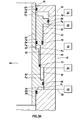
- FIGS. 3A-C enlarged scale cross-sectional views of one example of the actuator 18 are representatively illustrated.
- FIG. 3A corresponds to the first position of the operating member 38
- FIG. 3B corresponds to the second position of the operating member
- FIG. 3C corresponds to the third position of the operating member as described above.
- the operating member 38 comprises an upper end of a first piston 40 reciprocably disposed in the actuator 18.
- a second piston 42 is also reciprocably disposed in the actuator 18.
- the piston 40 and operating member 38 are depicted in FIG. 2 as being only a single structure, and the piston 42 is depicted in FIG. 2 as being only a single structure, but any or all of these could comprise multiple structures in keeping with the principles of this disclosure.
- the first piston 40 is sealingly received in bores 58, 60, 62, 64 with respective seals 66, 68, 70, 72.
- the second piston 42 is sealingly received in bores 74, 76 with respective seals 78, 80.
- the first piston 40 is sealingly received in a bore 82 in the second piston 42 with a seal 84.
- the bores 58, 60 define a first surface area A1 on the first piston 40 which is exposed to the first chamber 24, the bores 64, 76 define a second surface area A2 on the second piston 42 which is exposed to the second chamber 26, the bores 62, 82 define a third surface area A3 on the first piston which is exposed to the third chamber 28, the bores 74, 82 define a fourth surface area A4 on the second piston which is exposed to the third chamber 28, the bores 60, 62 define a fifth surface area A5 on the first piston which is exposed to the fourth chamber 30, and the bores 74, 76 define a sixth surface area A6 on the second piston which is exposed to the fifth chamber 32.
- the surface area A1 is equal to the sum of the surface areas A3 and A5
- the surface area A2 is equal to the sum of the surface areas A4 and A6. It is also preferred that the surface area A2 is greater than the surface area A1 , and that the surface area A4 is greater than the surface area A3.
- the high pressure source 20 is in communication with the second chamber 26, and the low pressure source 22 is in communication with the first chamber 24.
- the first piston 40 being biased downwardly (since the chamber 30 is in communication with the high pressure source 20 and both of the chambers 24, 28 are at relatively low pressures), and the second piston 42 being biased downwardly (since the chambers 26, 32 are in communication with the high pressure source 20 and the chamber 28 is at a relatively low pressure).
- the stroke of the piston 40 is limited by an upset due to seal bore 62.
- the operating member 38 and piston 40 are at the first position.
- both of chambers 24, 26 are in communication with the high pressure source 20.
- the second piston 42 prevents the first piston 40 from displacing further upward, due to abutting contact between the second piston 42 and a shoulder 86 on the first piston.
- the first piston 40 cannot displace the second piston 42 upwardly, since the surface area A4 on the second piston is greater than the surface area A3 on the first piston.
- the operating member 38 is displaced to the second position with the piston 40.
- the first chamber 24 is in communication with the high pressure source 20 and the second chamber is in communication with the low pressure source 22.
- the operating member 38 is displaced further upward with the piston 40 to the third position.
- FIG. 4 another configuration of the actuator 18 is representatively illustrated.
- the operating member 38 is connected at a lower end of the first piston 40, the operating member is displaced to operate another well tool 88, and the pistons 40, 42 are in the form of solid cylindrical elements, instead of annular elements as depicted in FIGS. 3A-C .
- the operation of the actuator 18 of FIG. 4 is the same as operation of the actuator of FIGS. 3A-C .
- the well tool 88 may be any type of well tool, such as a packer, plug, hanger, flow control device, gravel packing tool, running tool, setting tool, etc.
- the configuration of FIG. 4 demonstrates that various configurations of the actuator 18 are possible, without departing from the principles of this disclosure.
- the actuator 18 can be operated to displace the operating member 38 to more than two positions by manipulating pressure in only two lines 34, 36, with the pressure being supplied from only two pressure sources 20, 22.
- This aspect of the disclosure is of considerable importance when design space is limited, which is common among downhole tool applications. Of course, other numbers of positions, lines and pressure sources may be utilized, if desired.
- the above disclosure describes a method of actuating at least one well tool 44, 46, 88 utilizing first and second pressure sources 20, 22.
- the method includes the steps of: placing a first chamber 24 of an actuator 18 for the well tool(s) 44, 46, 88 in communication with the first pressure source 20, thereby displacing a first piston 40 from a first position to a second position; and then placing a second chamber 26 of the actuator 18 in communication with the second pressure source 22, thereby displacing the first piston 40 from the second position to a third position.
- a second piston 42 may prevent displacement of the first piston 40 to the third position until the second chamber 26 is placed in communication with the second pressure source 22.
- a third chamber 28 may be at a lower pressure relative to the first pressure source 20 at each of the first, second and third positions of the first piston 40.
- Each of the first and second pistons 40, 42 may be exposed to the third chamber 28 while the first piston 40 is at each of the first, second and third positions.
- the second chamber 26 may be in communication with the first pressure source 20 during the step of placing the first chamber 24 in communication with the first pressure source 20.
- the method may also include the steps of operating a first well tool 46 in response to displacing the first piston 40 from the first position to the second position, and operating a second well tool 44 in response to displacing the first piston 40 from the second position to the third position.
- a multi-position actuator 18 for actuating at least one well tool 44, 46, 88 utilizing first and second pressure sources 20, 22.
- the actuator 18 includes first and second chambers 24, 26 in the actuator 18, and an operating member 38 which displaces to operate the well tool(s) 44, 46, 88.
- a first position of the operating member 38 corresponds to the second pressure source 22 being in communication with the first chamber 24 and the first pressure source 20 being in communication with the second chamber 26.
- a second position of the operating member 38 corresponds to the first pressure source 20 being in communication with each of the first and second chambers 24, 26.
- a third position of the operating member 38 corresponds to the first pressure source 20 being in communication with the first chamber 24 and the second pressure source 22 being in communication with the second chamber 26.
- the first pressure source 20 may supply a higher pressure than the second pressure source 22.
- the actuator 18 may also include first and second pistons 40, 42.
- the first piston 40 may be exposed to the first chamber 24, and the second piston 42 may be exposed to the second chamber 26.
- the actuator 18 may include a third chamber 28 at a lower pressure relative to the first pressure source 20 at each of the first, second and third positions of the operating member 38.
- the first and second pistons 40, 42 may be exposed to the third chamber 28 at each of the first, second and third positions of the operating member 38.
- the actuator 18 may also include fourth and fifth chambers 30, 32 in communication with the first pressure source 20 at each of the first, second and third positions of the operating member 38.
- the first piston 40 may be exposed to the fourth chamber 30 at each of the first, second and third positions of the operating member 38, and the second piston 42 may be exposed to the fifth chamber 32 at each of the first, second and third positions of the operating member 38.
- a multi-position actuator 18 for actuating at least one well tool 44, 46, 88 utilizing first and second pressure sources 20, 22, with the actuator 18 including first and second chambers 24, 26 in the actuator 18, and a first piston 40 which displaces an operating member 38 to operate the well tool(s) 44, 46, 88.
- the first piston 40 has a first position in the actuator 18 corresponding to the second pressure source 22 being in communication with the first chamber 24 and the first pressure source 20 being in communication with the second chamber 26.
- the first piston 40 has a second position in the actuator 18 corresponding to the first pressure source 20 being in communication with each of the first and second chambers 24, 26.
- the first piston 40 has a third position in the actuator 18 corresponding to the first pressure source 20 being in communication with the first chamber 24 and the second pressure source 22 being in communication with the second chamber 26.
- the second position may be located between the first and third positions.
- the first piston 40 may have a first surface area A1 exposed to the first chamber 24.
- the actuator 18 may include a second piston 42 having a second surface area A2 exposed to the second chamber 26.
- the second surface area A2 may be greater than the first surface area A1 .
- the first piston 40 may be biased into contact with the second piston 42, thereby preventing displacement of the first piston 40 to the third position, when the first piston 40 is in the second position.
- the first and second pistons 40, 42 may be exposed to the second pressure source 22 at each of the first, second and third positions of the first piston 40.
- the first piston 40 may have a third surface area A3 exposed to a low pressure relative to the first pressure source 20.
- the second piston 42 may have a fourth surface area A4 exposed to the low pressure relative to the first pressure source 20.
- the fourth surface area A4 may be greater than the third surface area A3.
- the first piston 40 may have a fifth surface area A5 exposed to the first pressure source 20, and the second piston 42 may have a sixth surface area A6 exposed to the first pressure source 20.
- a difference between the first and fifth surface areas A1 , A5 on the first piston 40 may be less than a difference between the second and sixth surface areas A2, A6 on the second piston 42.
Landscapes
- Life Sciences & Earth Sciences (AREA)
- Engineering & Computer Science (AREA)
- Geology (AREA)
- Mining & Mineral Resources (AREA)
- Physics & Mathematics (AREA)
- Environmental & Geological Engineering (AREA)
- Fluid Mechanics (AREA)
- General Life Sciences & Earth Sciences (AREA)
- Geochemistry & Mineralogy (AREA)
- Actuator (AREA)
Applications Claiming Priority (1)
| Application Number | Priority Date | Filing Date | Title |
|---|---|---|---|
| US12/352,901 US8087463B2 (en) | 2009-01-13 | 2009-01-13 | Multi-position hydraulic actuator |
Publications (1)
| Publication Number | Publication Date |
|---|---|
| EP2206878A2 true EP2206878A2 (en) | 2010-07-14 |
Family
ID=41718551
Family Applications (1)
| Application Number | Title | Priority Date | Filing Date |
|---|---|---|---|
| EP10150651A Withdrawn EP2206878A2 (en) | 2009-01-13 | 2010-01-13 | Multi-position hydraulic actuator |
Country Status (3)
| Country | Link |
|---|---|
| US (1) | US8087463B2 (pt) |
| EP (1) | EP2206878A2 (pt) |
| BR (1) | BRPI1000177B1 (pt) |
Cited By (2)
| Publication number | Priority date | Publication date | Assignee | Title |
|---|---|---|---|---|
| WO2014126568A1 (en) | 2013-02-14 | 2014-08-21 | Halliburton Energy Services, Inc. | Stacked piston safety valve with different piston diameters |
| US9695659B2 (en) | 2013-11-11 | 2017-07-04 | Halliburton Energy Services, Inc | Pipe swell powered tool |
Families Citing this family (4)
| Publication number | Priority date | Publication date | Assignee | Title |
|---|---|---|---|---|
| US20130068472A1 (en) * | 2011-09-19 | 2013-03-21 | Baker Hughes Incorporated | Hydraulic Three Position Stroker Tool |
| US20140000908A1 (en) * | 2012-06-28 | 2014-01-02 | Schlumberger Technology Corporation | Actuating device and method |
| US9228413B2 (en) * | 2013-01-18 | 2016-01-05 | Halliburton Energy Services, Inc. | Multi-stage setting tool with controlled force-time profile |
| US10364653B2 (en) * | 2016-10-28 | 2019-07-30 | Baker Hughes, A Ge Company, Llc | Actuation tool having a non-ballistic force generating mechanism |
Family Cites Families (48)
| Publication number | Priority date | Publication date | Assignee | Title |
|---|---|---|---|---|
| US3092135A (en) | 1956-04-27 | 1963-06-04 | Cicero C Brown | Full opening safety valve for pipe strings |
| US3494419A (en) | 1968-04-24 | 1970-02-10 | Schlumberger Technology Corp | Selectively-operable well tools |
| US3533430A (en) | 1969-01-01 | 1970-01-01 | Otis Eng Corp | Shuttle valve |
| US3762471A (en) | 1971-04-06 | 1973-10-02 | Hydril Co | Subsurface well apparatus and method |
| FR2165719B1 (pt) | 1971-12-27 | 1974-08-30 | Subsea Equipment Ass Ltd | |
| US4025883A (en) | 1975-11-11 | 1977-05-24 | Westinghouse Electric Corporation | Modular integral motor controller |
| US4230187A (en) | 1979-06-19 | 1980-10-28 | Trw Inc. | Methods and apparatus for sensing wellhead pressure |
| US4347900A (en) | 1980-06-13 | 1982-09-07 | Halliburton Company | Hydraulic connector apparatus and method |
| DE3024963A1 (de) | 1980-07-02 | 1982-01-28 | Robert Bosch Gmbh, 7000 Stuttgart | Kraftstoffeinspritzeinrichtung fuer brennkraftmaschinen, insbesondere fuer dieselmotoren |
| US4421174A (en) | 1981-07-13 | 1983-12-20 | Baker International Corporation | Cyclic annulus pressure controlled oil well flow valve and method |
| US4431174A (en) * | 1981-12-11 | 1984-02-14 | Arnold Varden | Vice |
| US4566478A (en) | 1982-04-27 | 1986-01-28 | Otis Engineering Corporation | Well safety and kill valve |
| US4633952A (en) | 1984-04-03 | 1987-01-06 | Halliburton Company | Multi-mode testing tool and method of use |
| US4658904A (en) | 1985-05-31 | 1987-04-21 | Schlumberger Technology Corporation | Subsea master valve for use in well testing |
| GB8712056D0 (en) | 1987-05-21 | 1987-06-24 | British Petroleum Co Plc | Insert choke & control module |
| US4922423A (en) | 1987-12-10 | 1990-05-01 | Koomey Paul C | Position and seal wear indicator for valves and blowout preventers |
| FR2647500B1 (fr) * | 1989-05-24 | 1996-08-09 | Schlumberger Prospection | Appareil d'essai d'un puits de forage petrolier et procede correspondant |
| US4979568A (en) | 1990-01-16 | 1990-12-25 | Baker Hughes Incorporated | Annulus fluid pressure operated testing valve |
| US4986357A (en) | 1990-04-09 | 1991-01-22 | Pringle Ronald E | Well tool having a variable area hydraulic actuator |
| US5050681A (en) | 1990-07-10 | 1991-09-24 | Halliburton Company | Hydraulic system for electronically controlled pressure activated downhole testing tool |
| BR9005123A (pt) | 1990-10-12 | 1992-06-30 | Petroleo Brasileiro Sa | Sistema submarino de producao |
| US5127477A (en) | 1991-02-20 | 1992-07-07 | Halliburton Company | Rechargeable hydraulic power source for actuating downhole tool |
| AU1100992A (en) | 1991-02-20 | 1992-08-27 | Halliburton Company | Hydraulic system for electronically controlled downhole testing tool |
| US5251703A (en) | 1991-02-20 | 1993-10-12 | Halliburton Company | Hydraulic system for electronically controlled downhole testing tool |
| US5101907A (en) | 1991-02-20 | 1992-04-07 | Halliburton Company | Differential actuating system for downhole tools |
| US5234057A (en) | 1991-07-15 | 1993-08-10 | Halliburton Company | Shut-in tools |
| US5271313A (en) | 1991-11-12 | 1993-12-21 | Lindegren Iii Carl J | Position-controlled actuator |
| US5273113A (en) | 1992-12-18 | 1993-12-28 | Halliburton Company | Controlling multiple tool positions with a single repeated remote command signal |
| US5412568A (en) | 1992-12-18 | 1995-05-02 | Halliburton Company | Remote programming of a downhole tool |
| US5995449A (en) | 1995-10-20 | 1999-11-30 | Baker Hughes Inc. | Method and apparatus for improved communication in a wellbore utilizing acoustic signals |
| US6085845A (en) | 1996-01-24 | 2000-07-11 | Schlumberger Technology Corporation | Surface controlled formation isolation valve adapted for deployment of a desired length of a tool string in a wellbore |
| US5831156A (en) | 1997-03-12 | 1998-11-03 | Mullins; Albert Augustus | Downhole system for well control and operation |
| US5890542A (en) | 1997-04-01 | 1999-04-06 | Halliburton Energy Services, Inc. | Apparatus for early evaluation formation testing |
| US6419022B1 (en) | 1997-09-16 | 2002-07-16 | Kerry D. Jernigan | Retrievable zonal isolation control system |
| US6422315B1 (en) | 1999-09-14 | 2002-07-23 | Quenton Wayne Dean | Subsea drilling operations |
| US6536530B2 (en) | 2000-05-04 | 2003-03-25 | Halliburton Energy Services, Inc. | Hydraulic control system for downhole tools |
| US6917857B2 (en) | 2000-12-15 | 2005-07-12 | American Standard International Inc. | Magnetically overridden flow control device |
| GB2370340B (en) | 2000-12-18 | 2003-05-21 | Tripat Singh Mangat | Valve |
| US7111675B2 (en) | 2001-08-20 | 2006-09-26 | Baker Hughes Incorporated | Remote closed system hydraulic actuator system |
| US6799633B2 (en) | 2002-06-19 | 2004-10-05 | Halliburton Energy Services, Inc. | Dockable direct mechanical actuator for downhole tools and method |
| US7234527B2 (en) | 2002-07-03 | 2007-06-26 | Halliburton Energy Services, Inc. | System and method for fail-safe disconnect from a subsea well |
| US6782952B2 (en) | 2002-10-11 | 2004-08-31 | Baker Hughes Incorporated | Hydraulic stepping valve actuated sliding sleeve |
| EP1597455B1 (en) | 2003-02-18 | 2007-09-19 | Baker Hughes Incorporated | Radially adjustable downhole devices & methods for the same |
| US7140436B2 (en) | 2003-04-29 | 2006-11-28 | Schlumberger Technology Corporation | Apparatus and method for controlling the pressure of fluid within a sample chamber |
| US7201230B2 (en) | 2003-05-15 | 2007-04-10 | Halliburton Energy Services, Inc. | Hydraulic control and actuation system for downhole tools |
| US7552773B2 (en) * | 2005-08-08 | 2009-06-30 | Halliburton Energy Services, Inc. | Multicycle hydraulic control valve |
| BRPI0713396B1 (pt) | 2006-07-03 | 2017-12-26 | Bj Services Company | Catraca steering mechanism |
| US7866402B2 (en) | 2007-10-11 | 2011-01-11 | Halliburton Energy Services, Inc. | Circulation control valve and associated method |
-
2009
- 2009-01-13 US US12/352,901 patent/US8087463B2/en active Active
-
2010
- 2010-01-07 BR BRPI1000177-8 patent/BRPI1000177B1/pt not_active IP Right Cessation
- 2010-01-13 EP EP10150651A patent/EP2206878A2/en not_active Withdrawn
Non-Patent Citations (1)
| Title |
|---|
| None |
Cited By (4)
| Publication number | Priority date | Publication date | Assignee | Title |
|---|---|---|---|---|
| WO2014126568A1 (en) | 2013-02-14 | 2014-08-21 | Halliburton Energy Services, Inc. | Stacked piston safety valve with different piston diameters |
| EP2956617A4 (en) * | 2013-02-14 | 2016-11-02 | Halliburton Energy Services Inc | SAFETY VALVE WITH STACKED PISTON AND DIFFERENT PISTON DIAMETERS |
| US10030475B2 (en) | 2013-02-14 | 2018-07-24 | Halliburton Energy Services, Inc. | Stacked piston safety valve with different piston diameters |
| US9695659B2 (en) | 2013-11-11 | 2017-07-04 | Halliburton Energy Services, Inc | Pipe swell powered tool |
Also Published As
| Publication number | Publication date |
|---|---|
| BRPI1000177B1 (pt) | 2019-12-10 |
| US20100175871A1 (en) | 2010-07-15 |
| BRPI1000177A2 (pt) | 2011-06-14 |
| US8087463B2 (en) | 2012-01-03 |
Similar Documents
| Publication | Publication Date | Title |
|---|---|---|
| US8453746B2 (en) | Well tools with actuators utilizing swellable materials | |
| AU2008310949B2 (en) | Circulation control valve and associated method | |
| US6302199B1 (en) | Mechanism for dropping a plurality of balls into tubulars used in drilling, completion and workover of oil, gas and geothermal wells | |
| US7455114B2 (en) | Snorkel device for flow control | |
| CA2585358C (en) | Downhole electrical-to-hydraulic conversion module for well completions | |
| US8360158B2 (en) | Overriding a primary control subsystem of a downhole tool | |
| US10287843B2 (en) | Pressure assisted blowout preventer | |
| US20100212910A1 (en) | Fluid metering device and method for well tool | |
| US8087463B2 (en) | Multi-position hydraulic actuator | |
| US20060254763A1 (en) | Single line control module for well tool actuation | |
| US11053774B2 (en) | Tubing or annulus pressure operated borehole barrier valve | |
| US9695679B2 (en) | Downhole zone flow control system | |
| GB2448434A (en) | Snorkel device for flow control | |
| US7552773B2 (en) | Multicycle hydraulic control valve | |
| US20110232916A1 (en) | Bi-directional flapper/sealing mechanism and technique | |
| US20100096134A1 (en) | Well Systems and Associated Methods Incorporating Fluid Loss Control | |
| US20130213666A1 (en) | Operation of multiple interconnected hydraulic actuators in a subterranean well | |
| CA2535080C (en) | Snorkel device for flow control | |
| CA2860778A1 (en) | Operation of multiple interconnected hydraulic actuators in a subterranean well |
Legal Events
| Date | Code | Title | Description |
|---|---|---|---|
| PUAI | Public reference made under article 153(3) epc to a published international application that has entered the european phase |
Free format text: ORIGINAL CODE: 0009012 |
|
| AK | Designated contracting states |
Kind code of ref document: A2 Designated state(s): AT BE BG CH CY CZ DE DK EE ES FI FR GB GR HR HU IE IS IT LI LT LU LV MC MK MT NL NO PL PT RO SE SI SK SM TR |
|
| AX | Request for extension of the european patent |
Extension state: AL BA RS |
|
| STAA | Information on the status of an ep patent application or granted ep patent |
Free format text: STATUS: THE APPLICATION HAS BEEN PUBLISHED |
|
| STAA | Information on the status of an ep patent application or granted ep patent |
Free format text: STATUS: THE APPLICATION IS DEEMED TO BE WITHDRAWN |
|
| 18D | Application deemed to be withdrawn |
Effective date: 20170801 |