EP2206915A2 - Windgenerator - Google Patents
Windgenerator Download PDFInfo
- Publication number
- EP2206915A2 EP2206915A2 EP09180415A EP09180415A EP2206915A2 EP 2206915 A2 EP2206915 A2 EP 2206915A2 EP 09180415 A EP09180415 A EP 09180415A EP 09180415 A EP09180415 A EP 09180415A EP 2206915 A2 EP2206915 A2 EP 2206915A2
- Authority
- EP
- European Patent Office
- Prior art keywords
- generator
- wind
- diffuser
- end fairing
- accordance
- Prior art date
- Legal status (The legal status is an assumption and is not a legal conclusion. Google has not performed a legal analysis and makes no representation as to the accuracy of the status listed.)
- Withdrawn
Links
Images

Classifications
-
- F—MECHANICAL ENGINEERING; LIGHTING; HEATING; WEAPONS; BLASTING
- F03—MACHINES OR ENGINES FOR LIQUIDS; WIND, SPRING, OR WEIGHT MOTORS; PRODUCING MECHANICAL POWER OR A REACTIVE PROPULSIVE THRUST, NOT OTHERWISE PROVIDED FOR
- F03D—WIND MOTORS
- F03D1/00—Wind motors with rotation axis substantially parallel to the air flow entering the rotor
- F03D1/04—Wind motors with rotation axis substantially parallel to the air flow entering the rotor having stationary wind-guiding means, e.g. with shrouds or channels
-
- F—MECHANICAL ENGINEERING; LIGHTING; HEATING; WEAPONS; BLASTING
- F05—INDEXING SCHEMES RELATING TO ENGINES OR PUMPS IN VARIOUS SUBCLASSES OF CLASSES F01-F04
- F05B—INDEXING SCHEME RELATING TO WIND, SPRING, WEIGHT, INERTIA OR LIKE MOTORS, TO MACHINES OR ENGINES FOR LIQUIDS COVERED BY SUBCLASSES F03B, F03D AND F03G
- F05B2240/00—Components
- F05B2240/10—Stators
- F05B2240/13—Stators to collect or cause flow towards or away from turbines
-
- Y—GENERAL TAGGING OF NEW TECHNOLOGICAL DEVELOPMENTS; GENERAL TAGGING OF CROSS-SECTIONAL TECHNOLOGIES SPANNING OVER SEVERAL SECTIONS OF THE IPC; TECHNICAL SUBJECTS COVERED BY FORMER USPC CROSS-REFERENCE ART COLLECTIONS [XRACs] AND DIGESTS
- Y02—TECHNOLOGIES OR APPLICATIONS FOR MITIGATION OR ADAPTATION AGAINST CLIMATE CHANGE
- Y02B—CLIMATE CHANGE MITIGATION TECHNOLOGIES RELATED TO BUILDINGS, e.g. HOUSING, HOUSE APPLIANCES OR RELATED END-USER APPLICATIONS
- Y02B10/00—Integration of renewable energy sources in buildings
- Y02B10/30—Wind power
-
- Y—GENERAL TAGGING OF NEW TECHNOLOGICAL DEVELOPMENTS; GENERAL TAGGING OF CROSS-SECTIONAL TECHNOLOGIES SPANNING OVER SEVERAL SECTIONS OF THE IPC; TECHNICAL SUBJECTS COVERED BY FORMER USPC CROSS-REFERENCE ART COLLECTIONS [XRACs] AND DIGESTS
- Y02—TECHNOLOGIES OR APPLICATIONS FOR MITIGATION OR ADAPTATION AGAINST CLIMATE CHANGE
- Y02E—REDUCTION OF GREENHOUSE GAS [GHG] EMISSIONS, RELATED TO ENERGY GENERATION, TRANSMISSION OR DISTRIBUTION
- Y02E10/00—Energy generation through renewable energy sources
- Y02E10/70—Wind energy
- Y02E10/72—Wind turbines with rotation axis in wind direction
Definitions
- Useful model relates to the wind-power engineering, namely to the devices for the obtaining electrical power by nontraditional methods. For obtaining electrical power this wind generator uses wind force.
- the plant is equipped with the additional guiding devices, whose air ducts are connected with the housing, and air inlet device is made in the form of a diffuser, located in the housing, connected with it air ducts and motorised rotary exhaust ducts, in this case the inlets of air ducts have a form of a truncated cone, and the outlets of branch pipes are oriented to the side, opposite to the air inlets.
- the closest to the declared useful model is the wind power unit, which has a wind turbine in the working channel with the converging nozzle section at the entrance and the diffuser at the output, kinematically connected with a revolving shaft with the electric generator located outside of the unit ( RU, the patent of No 2156885 , F03D 3/04, published 27.09.2000 g.).
- the wind turbine is established in the working channel in the common block with the diffuser and the converging nozzle section.
- On its axis a conical air separator is installed, it has guiding plates rigidly fixed on its surface for forcing to the wind current into rotation at a specific angle.
- a deficiency of that power unit is in the fact that with the use of the wind turbine, installed in the working channel in the common block with the diffuser and the converging nozzle section, and the presence on its axis of the conical divider of air with those rigidly fixed on its surface guiding plates does not ensure a high speed of the wind current in the working channel, thereby negatively affecting effectiveness of collecting the wind energy (wind efficiency).
- location of electric generator outside the unit requires the use in the working channel of different parts, for example a conical cogwheel pair, which changes the direction of shaft from the horizontal to the vertical. This leads to an increase in the resistance to the wind current in the working channel, and, therefore, to reduction in its speed.
- the useful model is based on the requirement to increase the velocity of the wind current in the working channel of wind generator, which will result in higher effectiveness of collection of wind power (wind efficiency).
- the wind generator which includes the wind turbine installed within the working channel in the common block with the diffuser and the converging nozzle section, connected by a revolving shaft with the electric generator, and the guiding plates for forcing to the wind current into rotation at a specific angle
- the end fairing which can be made in various shapes, for example, in the form of two cones, facing each other by their bases, and installed in relation to the diffuser in such a way that an annular diagonal channel is formed with a possibility of movement in relation to the diffuser along its longitudinal axis; the guiding plates are installed at the entrance into the converging nozzle section and the electric generator is placed in the end fairing.
- end fairing which can be made in various shapes, for example, in the form of two cones, facing each other by their bases, and installed in relation to the diffuser in such a way that an annular diagonal channel is formed and movement along its longitudinal axis is possible; and installation of the guiding of plates at the entrance into converging nozzle section and placing the electric generator in the end fairing provides an increase in the velocity of the wind current in the working channel of wind generator, thereby increasing the effectiveness of the collection of wind power (wind efficiency).
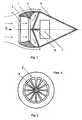
- Fig.1 shows the longitudinal section of the wind generator
- Fig.2 shows the view specified by arrow "A" on Fig. 1
- Fig.3 shows the side view of the wind generator
- Fig.4 shows wind turbine.
- the wind generator contains the wind turbine 1, installed in the working channel in the common block with converging nozzle section 2 and diffuser 3, the guiding plates 4 for forcing the wind current into rotation at the specific angle, and the end fairing 5, which can be made in various shapes, for example, in the form of two cones, facing each other by their bases.
- the guiding plates 4 are installed at the entrance into converging nozzle section 2.
- the wind turbine is connected by a revolving shaft 6 to the electric generator 7.
- the end fairing 5 is placed to diffuser 3 in such a way that an annular diagonal channel is formed and movement is along its longitudinal axis is possible. Movement of the end fairing 5 in relation to diffuser 3 ensures optimization of the parameters of wind generator Electric generator 7 is placed in end fairing 5.
- the rotor (not shown) of electric generator 7 is fixed to the revolving shaft 6, the stator (not shown) is connected to the end fairing 5.
- the wind generator works as follows.
- the surrounding air passes guiding plates 4 installed at the entrance into converging nozzle 2 and, after obtaining rotary motion, it enters into converging nozzle 2 where, due to the decrease of the section of converging nozzle 2 it acquires faster rotation and becomes a high-speed revolving air flow which reaches the blades of wind turbine 1.
- the air flow sets the turbine into rotation, thereby setting into rotation the rotor fixed on shaft 6 in relation to the stator fixed on end fairing 5.
- end fairing 5 Because of the presence of the annular diagonal channel, formed by the end fairing 5 and the diffuser 3, rarefaction is created in the space after the blades of the wind turbine 1 which ensures rapid withdrawal of the exhaust air flow from diffuser 3, thereby increasing the air velocity in the working channel. Optimization of the parameters of wind generator is accomplished by movement of end fairing 5 along the longitudinal axis in relation to diffuser 3.
- the end fairing 5, which can be made in various shapes, for example, in the form of two cones, facing each other by their bases, serves not only for formation of the annular diagonal channel, but also ensures elimination of stall effects.
- the construction of the wind generator increases effectiveness of collection of wind power (wind efficiency) to 34-37% with different speeds of wind (from 1 m/s to 15 m/s).
- the construction is safe in operating conditions for the service personnel and random birds, it has a lower level of noise and does not have low-frequency acoustic fluctuations.
- the wind generator can be installed on the building roofs close to the end users of the produced electrical energy.
- the wind generator which includes a wind turbine installed within the working channel in a common block with the diffuser and the converging nozzle section, connected via a revolving shaft to an electric generator, and the guiding plates for forcing to the wind current into rotation at a specific angle, differs from the known patented wind generators with internal wind turbine, converging nozzle and diffuser by the fact that it is equipped with the end fairing, which can be made in various shapes, for example, in the form of two cones, facing each other by their bases, and installed in relation to the diffuser in such a way that an annular diagonal channel is formed with a possibility of movement in relation to the diffuser along its longitudinal axis; the guiding plates are installed at the entrance into the converging nozzle section and the electric generator is placed in the end fairing.
Landscapes
- Engineering & Computer Science (AREA)
- Life Sciences & Earth Sciences (AREA)
- Sustainable Development (AREA)
- Sustainable Energy (AREA)
- Chemical & Material Sciences (AREA)
- Combustion & Propulsion (AREA)
- Mechanical Engineering (AREA)
- General Engineering & Computer Science (AREA)
- Wind Motors (AREA)
Applications Claiming Priority (2)
| Application Number | Priority Date | Filing Date | Title |
|---|---|---|---|
| RU2008151669 | 2008-12-25 | ||
| GB0903960A GB2467023B (en) | 2008-12-25 | 2009-03-06 | Wind generator |
Publications (2)
| Publication Number | Publication Date |
|---|---|
| EP2206915A2 true EP2206915A2 (de) | 2010-07-14 |
| EP2206915A3 EP2206915A3 (de) | 2011-03-30 |
Family
ID=40600683
Family Applications (1)
| Application Number | Title | Priority Date | Filing Date |
|---|---|---|---|
| EP09180415A Withdrawn EP2206915A3 (de) | 2008-12-25 | 2009-12-22 | Windgenerator |
Country Status (2)
| Country | Link |
|---|---|
| EP (1) | EP2206915A3 (de) |
| GB (1) | GB2467023B (de) |
Cited By (4)
| Publication number | Priority date | Publication date | Assignee | Title |
|---|---|---|---|---|
| JP4857424B1 (ja) * | 2011-02-22 | 2012-01-18 | 滿國 高田 | 風力発電装置 |
| EP2395235A3 (de) * | 2010-06-11 | 2014-04-16 | Dr. Ing. h.c. F. Porsche AG | Windkraftanlage mit tropfenförmigem Gehäuse |
| AT515392A1 (de) * | 2014-01-09 | 2015-08-15 | Mehmet Dipl Ing Fh Demirel | Staudruck Windrad |
| NO347729B1 (no) * | 2022-09-16 | 2024-03-11 | Randsea As | Skovlelement omfattende kanal og lamell for bruk i havstrømsturbin |
Families Citing this family (2)
| Publication number | Priority date | Publication date | Assignee | Title |
|---|---|---|---|---|
| CN105015756B (zh) * | 2015-07-23 | 2017-03-08 | 北京天航华创科技股份有限公司 | 一种平流层飞艇用风能发电‑散热降温一体化结构 |
| US12203441B1 (en) * | 2023-03-18 | 2025-01-21 | Vincent Loccisano | Fluid turbine configured for moment-arm and thrust-force load control |
Family Cites Families (8)
| Publication number | Priority date | Publication date | Assignee | Title |
|---|---|---|---|---|
| US3339078A (en) * | 1964-12-17 | 1967-08-29 | Crompton George | Wind turbine electro-generators |
| US4079264A (en) * | 1976-05-03 | 1978-03-14 | Nathan Cohen | Wind or water operated power plant |
| US5464320A (en) * | 1993-06-02 | 1995-11-07 | Finney; Clifton D. | Superventuri power source |
| ATE284486T1 (de) * | 1996-10-22 | 2004-12-15 | Der Veken Germaine Van | Windturbine |
| RU2124142C1 (ru) * | 1998-03-25 | 1998-12-27 | Орлов Игорь Сергеевич | Ветроэнергетическая установка |
| JP2001055969A (ja) * | 1999-08-17 | 2001-02-27 | Nippon Safety Kk | 風車装置 |
| BE1013284A3 (nl) * | 2000-02-11 | 2001-11-06 | Adriaenssens Jozef | Inrichting voor het winnen van energie. |
| DE10157821A1 (de) * | 2001-11-24 | 2003-06-12 | Fritz Reinke | Windkraftanlage |
-
2009
- 2009-03-06 GB GB0903960A patent/GB2467023B/en not_active Expired - Fee Related
- 2009-12-22 EP EP09180415A patent/EP2206915A3/de not_active Withdrawn
Non-Patent Citations (1)
| Title |
|---|
| None |
Cited By (5)
| Publication number | Priority date | Publication date | Assignee | Title |
|---|---|---|---|---|
| EP2395235A3 (de) * | 2010-06-11 | 2014-04-16 | Dr. Ing. h.c. F. Porsche AG | Windkraftanlage mit tropfenförmigem Gehäuse |
| JP4857424B1 (ja) * | 2011-02-22 | 2012-01-18 | 滿國 高田 | 風力発電装置 |
| AT515392A1 (de) * | 2014-01-09 | 2015-08-15 | Mehmet Dipl Ing Fh Demirel | Staudruck Windrad |
| AT515392B1 (de) * | 2014-01-09 | 2016-03-15 | Mehmet Dipl Ing Fh Demirel | Staudruck Windrad |
| NO347729B1 (no) * | 2022-09-16 | 2024-03-11 | Randsea As | Skovlelement omfattende kanal og lamell for bruk i havstrømsturbin |
Also Published As
| Publication number | Publication date |
|---|---|
| EP2206915A3 (de) | 2011-03-30 |
| GB2467023B (en) | 2011-03-02 |
| GB2467023A (en) | 2010-07-21 |
| GB0903960D0 (en) | 2009-04-22 |
Similar Documents
| Publication | Publication Date | Title |
|---|---|---|
| EP2206915A2 (de) | Windgenerator | |
| EP2409024B1 (de) | Turbinenanordnung | |
| EP2395234A2 (de) | Tunnelantriebsturbinensystem zur Erzeugung potentieller Energie aus kinetischer Restenergie | |
| CN101103198A (zh) | 全向风轮机 | |
| EP1222388B1 (de) | Windenergieumformer | |
| EP2329140A2 (de) | Hydraulische turbinensysteme | |
| KR20180116418A (ko) | 건축물과 결합된 풍력 발전기 | |
| EA031486B1 (ru) | Ветровая электростанция, снабженная вращающимся вихреобразующим ветровым концентратором | |
| US20150361953A1 (en) | Horizontally channeled vertical axis wind turbine | |
| CN111911343A (zh) | 适于没有风力涡轮机塔的安装的改进的风力涡轮机 | |
| RU2215898C1 (ru) | Роторная ветроэлектростанция | |
| RU144302U1 (ru) | Ветродвигатель | |
| WO2013043774A1 (en) | High efficiency wind turbine having increased laminar airflow | |
| US20100111668A1 (en) | Ultra high power density wind turbine system | |
| RU132141U1 (ru) | Ветроэлектростанция | |
| EP3597900B1 (de) | Windturbine | |
| RU2156885C1 (ru) | Ветросиловая энергоустановка вращающегося типа | |
| RU82273U1 (ru) | Ветрогенератор | |
| RU2425249C1 (ru) | Роторная ветроэлектростанция | |
| RU2383775C1 (ru) | Роторная ветроустановка | |
| AU2009100798A4 (en) | Device for harnessing wind energy | |
| RU2270359C1 (ru) | Роторная ветроэлектростанция | |
| CN112112754B (zh) | 一种风力采集装置和风力发电装置 | |
| RU2623637C2 (ru) | Ветротепловой преобразователь-накопитель | |
| Saha et al. | Twisted bamboo bladed rotor for Savonius wind turbines |
Legal Events
| Date | Code | Title | Description |
|---|---|---|---|
| PUAI | Public reference made under article 153(3) epc to a published international application that has entered the european phase |
Free format text: ORIGINAL CODE: 0009012 |
|
| AK | Designated contracting states |
Kind code of ref document: A2 Designated state(s): AT BE BG CH CY CZ DE DK EE ES FI FR GB GR HR HU IE IS IT LI LT LU LV MC MK MT NL NO PL PT RO SE SI SK SM TR |
|
| AX | Request for extension of the european patent |
Extension state: AL BA RS |
|
| PUAL | Search report despatched |
Free format text: ORIGINAL CODE: 0009013 |
|
| AK | Designated contracting states |
Kind code of ref document: A3 Designated state(s): AT BE BG CH CY CZ DE DK EE ES FI FR GB GR HR HU IE IS IT LI LT LU LV MC MK MT NL NO PL PT RO SE SI SK SM TR |
|
| AX | Request for extension of the european patent |
Extension state: AL BA RS |
|
| 17P | Request for examination filed |
Effective date: 20110928 |
|
| STAA | Information on the status of an ep patent application or granted ep patent |
Free format text: STATUS: THE APPLICATION IS DEEMED TO BE WITHDRAWN |
|
| 18D | Application deemed to be withdrawn |
Effective date: 20130702 |