EP2207201B1 - Unité de refroidissement - Google Patents
Unité de refroidissement Download PDFInfo
- Publication number
- EP2207201B1 EP2207201B1 EP10003150.9A EP10003150A EP2207201B1 EP 2207201 B1 EP2207201 B1 EP 2207201B1 EP 10003150 A EP10003150 A EP 10003150A EP 2207201 B1 EP2207201 B1 EP 2207201B1
- Authority
- EP
- European Patent Office
- Prior art keywords
- plate
- liquid
- cooling unit
- cell
- distributing
- Prior art date
- Legal status (The legal status is an assumption and is not a legal conclusion. Google has not performed a legal analysis and makes no representation as to the accuracy of the status listed.)
- Expired - Lifetime
Links
Images


Classifications
-
- F—MECHANICAL ENGINEERING; LIGHTING; HEATING; WEAPONS; BLASTING
- F28—HEAT EXCHANGE IN GENERAL
- F28F—DETAILS OF HEAT-EXCHANGE AND HEAT-TRANSFER APPARATUS, OF GENERAL APPLICATION
- F28F9/00—Casings; Header boxes; Auxiliary supports for elements; Auxiliary members within casings
- F28F9/02—Header boxes; End plates
- F28F9/026—Header boxes; End plates with static flow control means, e.g. with means for uniformly distributing heat exchange media into conduits
- F28F9/0265—Header boxes; End plates with static flow control means, e.g. with means for uniformly distributing heat exchange media into conduits by using guiding means or impingement means inside the header box
- F28F9/0268—Header boxes; End plates with static flow control means, e.g. with means for uniformly distributing heat exchange media into conduits by using guiding means or impingement means inside the header box in the form of multiple deflectors for channeling the heat exchange medium
-
- F—MECHANICAL ENGINEERING; LIGHTING; HEATING; WEAPONS; BLASTING
- F28—HEAT EXCHANGE IN GENERAL
- F28F—DETAILS OF HEAT-EXCHANGE AND HEAT-TRANSFER APPARATUS, OF GENERAL APPLICATION
- F28F13/00—Arrangements for modifying heat-transfer, e.g. increasing, decreasing
- F28F13/06—Arrangements for modifying heat-transfer, e.g. increasing, decreasing by affecting the pattern of flow of the heat-exchange media
-
- F—MECHANICAL ENGINEERING; LIGHTING; HEATING; WEAPONS; BLASTING
- F28—HEAT EXCHANGE IN GENERAL
- F28F—DETAILS OF HEAT-EXCHANGE AND HEAT-TRANSFER APPARATUS, OF GENERAL APPLICATION
- F28F3/00—Plate-like or laminated elements; Assemblies of plate-like or laminated elements
- F28F3/12—Elements constructed in the shape of a hollow panel, e.g. with channels
-
- H—ELECTRICITY
- H05—ELECTRIC TECHNIQUES NOT OTHERWISE PROVIDED FOR
- H05K—PRINTED CIRCUITS; CASINGS OR CONSTRUCTIONAL DETAILS OF ELECTRIC APPARATUS; MANUFACTURE OF ASSEMBLAGES OF ELECTRICAL COMPONENTS
- H05K7/00—Constructional details common to different types of electric apparatus
- H05K7/20—Modifications to facilitate cooling, ventilating, or heating
- H05K7/2089—Modifications to facilitate cooling, ventilating, or heating for power electronics, e.g. for inverters for controlling motor
- H05K7/20927—Liquid coolant without phase change
-
- H—ELECTRICITY
- H10—SEMICONDUCTOR DEVICES; ELECTRIC SOLID-STATE DEVICES NOT OTHERWISE PROVIDED FOR
- H10W—GENERIC PACKAGES, INTERCONNECTIONS, CONNECTORS OR OTHER CONSTRUCTIONAL DETAILS OF DEVICES COVERED BY CLASS H10
- H10W40/00—Arrangements for thermal protection or thermal control
- H10W40/40—Arrangements for thermal protection or thermal control involving heat exchange by flowing fluids
- H10W40/47—Arrangements for thermal protection or thermal control involving heat exchange by flowing fluids by flowing liquids, e.g. forced water cooling
-
- F—MECHANICAL ENGINEERING; LIGHTING; HEATING; WEAPONS; BLASTING
- F28—HEAT EXCHANGE IN GENERAL
- F28D—HEAT-EXCHANGE APPARATUS, NOT PROVIDED FOR IN ANOTHER SUBCLASS, IN WHICH THE HEAT-EXCHANGE MEDIA DO NOT COME INTO DIRECT CONTACT
- F28D21/00—Heat-exchange apparatus not covered by any of the groups F28D1/00 - F28D20/00
- F28D2021/0019—Other heat exchangers for particular applications; Heat exchange systems not otherwise provided for
- F28D2021/0028—Other heat exchangers for particular applications; Heat exchange systems not otherwise provided for for cooling heat generating elements, e.g. for cooling electronic components or electric devices
- F28D2021/0029—Heat sinks
Definitions
- This invention relates to a cooling unit according to the preamble of claim 1, especially for liquid cooling of power semiconductors, where the component to be cooled is arranged on the upper side of a plate, and where the bottom side of the plate is cooled by a liquid, which is guided along the plate by means of a distributing element, and where the liquid inlet and the liquid outlet of the distributing element are arranged perpendicular to the plate.
- Such a cooling unit is known for example, from US 6 034 872 B2 .
- US 5,269,372 describes a cold plate for cooling power modules. Liquid is let through an inlet to a chamber, in which a manifold distributes the liquid through several holes into a cooling plate exhibiting inlet conduits and return conduits.
- the plate preferably manufactured in copper, is divided into a 6x6 cubicle matrix. Between each two cubes, a fluid channel connects an inlet conduit and a return conduit.
- This solution achives a reduction in the temperature gradient, but is expensive due to the need for a heat conducting cold plate. Making a cooling construction which avoids the necessity of a cold plate thus is of interest. Further, due to narrow channels and inlets, the flow resistance is high, thus limiting an increase in cooling capacity.
- US 5,841,634 discloses a liquid-cooled semiconductor device, like the one this invention relates to.
- the semiconductors are here placed inside a housing on a wall, which is to be cooled.
- the device shows a fluid inlet port and a fluid outlet port, and a baffle placed in a chamber inside the housing.
- the baffle includes a wall separating the chamber into a top-and a bottom portion, and walls separating each portion into compartment. A number of holes in the wall between top-and bottom portion provide fluid communication between the portions. Fluid is let from the inlet port to a first bottom compartment, and then through holes to a first top compartment. In the top compartment the fluid is let along the wall, which is to be cooled, and through holes to a second bottom compartment.
- the fluid is let to a second top compartment, where it cools another area of the wall, which is to be cooled. After having passed three top compartments the fluid it let to the fluid outlet port, and out of the device. Thus the cooling compartments of the device is connected in a serial manner.
- the cooling effect from the fluid will have lead to a higher outlet temperature than the inlet temperature.
- additional heating of the fluid will take place, and this will lead to a temperature difference on the cooled wall, from fluid inlet port end to fluid outlet port end.
- high power semiconductors are very sensitive to temperature variations, and also sensitive to the temperature level, equal cooling conditions for all semiconductors in a power semiconductor device will have a large impact on the lifetime for the device.
- serial connection of multiple cooling compartments will have a high flow resistance as a result, leading to a high pressure drop or a low flow rate of the fluid through the cooling device.
- US 3 918 084 A relates to a semiconductor rectifier arrangement.
- Said arrangement comprises a cooling element with a trough-shaped metallic base body having a rectangular shape.
- a meander-shaped cooling channel is formed therein by partitions. The latter extend from both longitudinal sides into the interior of the trough in an alternating arrangement.
- a pair of hollow connecting studs protrudes from the underside of the bottom of the plate of the base body into the ends of said cooling channel.
- the cooling element is provided with a thin cover which is provided with metal portions. The metal portions support a rectifier system which is to be cooled by the cooling element.
- US 5 835 345 A relates to a cooler for removing heat from a heated region. The cooler comprises a supply of coolant.
- the coolant is supplied to a manifold by means of an input conduit and removed therefrom via an output conduit.
- the cooler comprises a substrate with a surface. The surface is in contact with a heated region, such as a laser array.
- the manifold divides and distributes the coolant such that it enters micro channels. Each of said micro channels defines a flow path for the coolant by means of a plurality of baffles disposed in the flow path. Adjacent baffles define a volume in between them.
- US 5 170 319 A relates to an enhanced multichip module cooling with thermally optimized pistons and closely coupled convective cooling channels.
- the module comprises a cover plate, inlet and outlet distributor blocks, a channel section with a plurality of parallel channels, and a frame carrying a substrate with an array of integrated circuit chips mounted therein.
- a parallel/ series flow configuration within the parallel channels can be achieved.
- For a parallel flow the coolant enters the module through an inlet and is distributed in parallel to a first end of seven of the channels.
- a first flow distributor collects and re-distributes the coolant in parallel to a second bank of seven channels. The same is done by a second flow distributor before the coolant exits the channels via a collector and is expelled through an outlet.
- US 5 241 450 A relates to a three dimensional, multi-chip module.
- the integrated circuit module comprises an integrated circuit chip with a second major surface bonded to a micro channel structure including a plurality of grooves.
- a micro channel cover manifold is bonded to the micro channel structure.
- the manifold includes a coolant delivery channels fed by a coolant supply manifold.
- the supply manifold includes a first flow path with high pressure coolant for the channel and a second flow path with low pressure coolant for the channel.
- EP 0 453 786 A2 relates to a convection transfer system.
- the convection transfer system comprises a workpiece and a facesheet.
- the facesheet comprises fluid supply nozzles as well as fluid return nozzles.
- the fluid is fed to the supply nozzles, travels a short distance within a gap between the workpiece and the facesheet, and exits via the return nozzles. In this way, convective heat transfer from the workpiece to the fluid is provided.
- the workpiece is a printed circuit board substrate connected to integrated circuit chips. The chips are located between the substrate and a facesheet.
- the liquid, by the distributing element itself, is guided from a common inlet port of the device to all the liquid inlets, and from all the liquid outlets to a common outlet port of the device.
- the geometry of the bottom part of the cooling unit can hereby be formed by a plate element, and the common inlet port and outlet port can be made simply by adding a hole in the structure, leading to the first chamber, and another hole leading to the second chamber.
- the cooling unit contains more than one of the distributing elements, and has each of the distributing elements arranged perpendicular to the plates.
- the cooling unit is in this case a base part, which is able to contain a given number of distributing elements and a given number of plates, whereby larger units can be made divided into sections for mounting of the cooled components.
- the liquid flow in each cell along the plate follows passages, which cause a change of direction of the liquid.
- the turbulent liquid flow is obtained by narrow liquid passages in each cell, by a pattern of passages that lead to a change of direction in each cell or by a combination of the two.
- the liquid outlet of one cell is adjacent to the liquid inlet of another cell.
- the effect of an increase of liquid temperature across one cell is compensated by supplying cold inlet liquid to one cell next to the outlet of another cell.
- the size of the area covered by each cell is varied across the distribution unit. Cooling is hereby increased in the areas of the device where the heat generation is largest, or decreased in the areas where heat generation is low.
- the size of the areas covered by each cell is larger along the edges than in the centre of said distribution unit.
- the cooling efficiency is kept low along the edges, where the number of semiconductors are low, and the cooling instead is focused on the areas where the numbers of semiconductors are higher.
- Cooling can also be increased in specific cells by increasing the number of changes in flowdirection within a cell. More specific, two neighbouring cells may cover the same area, but by narrowing the channel width of one cell there will be room for an additional change in flow direction, i. e. an additional separating wall. The narrower the channel, the higher the flow velocity and thus a higher cooling is the result in the specific cell.
- the plate is made of a material with a low heat conduction resistance, i. e. high thermal conductivity.
- the heat transfer from one side of the plate to the other will hereby have a low impact on the total heat transfer resistance, and small temperature variations on the side of the plate facing the distributing element will be equalised on the other side of the plate. This will have an even more equal temperature for the semiconductors as a consequence.
- the plate itself is the substrate to which the semiconductors are attached.
- Heat transfer resistance from a separate intermediate cooling plate is hereby avoided, and the total heat transfer resistance is decreased.
- a problem particularly arising from direct cooling is the tendency of the plate to bend upwards due to increased heat impact.
- the cooling unit can be shaped in different ways, e. g. bent into a tubular shape hereby fitting into an electric motor housing and saving space.
- transition zones inbetween can contain fewer inlets and outlets per square centimeter than neighbouring distributing compartments. Hereby unnecessary pressure loss is avoided.
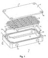
- the cooling unit 1 consists of a bottom part 13, formed as a bathtub with a plane bottom plate 11 and a frame part 20.
- the bottom part 13 has holes 14 and 15 for liquid connections from a pipe system or the like.
- a distributing element 4 fits with the internal surfaces of the frame part 20 of the bottom part 13. When the distributing element 4 is placed in the bottom part 13, it divides this into a top compartment and a bottom compartment.
- the bottom compartment is formed between the bottom plate 11 and the distributing element 4, and is further divided into two chambers, as will be described later.
- the holes 14 and 15 is in connection with this bottom compartment, and fluid communication between the bottom compartment and the top compartment will only occur through inlets 5 and outlets 6 in the distributing element 4, described in details later.
- a top plate 3 capsulate the top compartment, when it is mounted on the bottom part 13, by means of a sealing ring 16.
- This sealing ring 16 fits into a groove 17 of the bottom part 13, and seals between the frame part 20 and the top plate 3.
- the top plate 3 is fixed to the bottom part 13 by means of screws (not shown in the drawings), which through holes 19 in the top plate 3 are screwed into holes 18 of the bottom part 13.
- the top plate 3 is to be referred to as the cooled plate, since this plate is the one, which is cooled by the liquid led through the unit.
- the substrates containing the semiconductors are placed, in a manner that will be obvious to those skilled in the art.
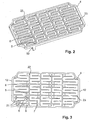
- FIG 2 shows the distributing element 4, in a perspective view slightly more angled than at Figure 1 .
- the inlets 5 and outlets 6 are now visible, and the top view of the distributing element 4 in Figure 3 makes the inlets 5 and outlets 6 even more visible.
- the guiding walls 21 allow liquid passage at one end of the wall. Some of the walls however run all the way through the structure, like wall 22 and 23. These through-going walls divides the top compartment into cells, each with an inlet 5 and an outlet 6.
- the inlet 5 and the outlet 6 are placed such that the outlet of one cell is next to an inlet of another cell. This have the effect that hot liquid, about to leave one cell, is close to cooling liquid, just entered another cell, and heat gradient along the cooled plate is hereby minimized.
- the heat gradient along the cooled plate is further minimized by varying the size of the area which the cells covers. Along the edges 12 the area of each cell is larger than on the rest of the surface, whereby the cooling in the area along the edges 12 is less effective than on the rest of the area. As the density of heat generating elements are smaller along the edges of a semiconductor device than on the rest of the device, a decreases in cooling effect along the edges will minimize the heat gradient along the cooled plate.
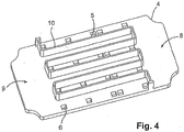
- Figure 4 shows a perspective view of the distributing element from the bottom side.
- the wall 10, running in a snake-like pattern along the bottom side, will bear on the bottom plate 11 of the bottom part 13, and forms a principally liquid-proof connection.
- the bottom compartment of the distributing element 4 is hereby divided into an inlet compartment 8, and an outlet compartment 9, when the distributing element is placed in the bottom part. All the inlets 5 are in connection with the inlet compartment 8, and all the outlets 6 are in connection with the outlet compartment 9.
- the cells of the top compartment, Figure 2 and 3 are thus all connected in parallel between the common inlet port and the common outlet port, position 14 and 15 of Figure 1 .
- the substrate to which the semiconductors are attached is placed on top of the cooled plate 3, in a way known to those skilled in the art.
- the cooled plate could however be the substrate itself, placed directly as a cover on the cooling unit. This is a consequence of the minimized heat gradient along the cooled plate, which makes the traditional heat spreading plate, shown in Figure 1 as the cooled plate 3, needless in some applications.
- Figure 8 shows an example of a directly cooled power module 45, the top lid being removed.
- the bottom part 13 incorporates the distributing element 4 (not visible) as shown in Figure 1 , and Direct Copper Bonding substrates (DCBs) 46,47 and 48 are connected to the housing and to electrical terminals 49 through wire bonds (not shown).
- DCBs Direct Copper Bonding substrates
- bridges 52 and 53 preferably consistsof a material different from the DCBs and are placed across the DCBs as shown, hereby counteracting the upwards motion of the DCB.
- the two ends of each bridge 52 and 53 are preferably fixated by nesting them into openings (not shown) in the housing 54. Alternatively, they can be glued or soldered onto the surface of the DCBs.
- the power module consists of three independent DCBs, but the bridges can be used for one large DCB also.
- FIG. 1 shows another embodiment of the invention.
- the cooling unit 30 has got a tubular shape with an inlet 32 and an outlet 31.
- Mounted on the cooling unit are power modules 25,26, 27,28 and 29 with terminals 33 for electrical connection.
- the power modules are mounted on the cooling unit with screws via holes 34.
- a tubular cooling unit like the one shown is used in an electrical motor and inserted into the motor in a way, that the side of the cooling unit 30 which has no power modules bears against the inside of the motor housing in order to minimize the space needed.
- the multi distributing element 35 shown from the top in Figure 6 is a part of the cooling unit 30 and placed inside, and exhibits guiding walls 21 and through-going walls 22 and 23. In difference to the single distributing element described hitherto, this multi distributing element contains six distributing compartments 36,37, 38,39, 40 and 41s corresponding to the number of power modules. However, there is only one liquid inlet and outlet which is common to all five distributors.
- the multi distributing element is divided into three sections 42,43 and 44, where sections 42 and 44 are integrally connected to section 43 and defines an obtuse angle to this section.
- Figure 7 shows the multi distributing 35 from the side opposite to the one shown in Figure 6 .
- the wall 10 divides this side of the distributor into an outlet compartment 9 and an inlet compartment 8. Through inlets 5 cooling liquid enters the meandering channels on the opposite side, and through outlets 6 the warm liquid is diverted away.
- the multi distributer 35 incorporates five distributors, only one separating wall 10 is used. In a transition zone two areas 50 and 51 each occupy a larger area than the other channels. In the transition zone no cooling is needed, because there is no power module on the opposite side.
- the areas 50 and 51 cover areas identical in size in order to avoid unbalancing the temperature distribution. Further, the number of outlets and inlets are reduced in the transition zone as compared to the corresponding areas in the distributing compartments hereby lowering the minimum amount of inlet pressure to the cooling unit.
- the distributing elements 4 and 35 are preferably manufactured as a pressure die cast hard plastic.
Landscapes
- Engineering & Computer Science (AREA)
- Physics & Mathematics (AREA)
- Thermal Sciences (AREA)
- Mechanical Engineering (AREA)
- General Engineering & Computer Science (AREA)
- Microelectronics & Electronic Packaging (AREA)
- Cooling Or The Like Of Semiconductors Or Solid State Devices (AREA)
- Secondary Cells (AREA)
- Thermotherapy And Cooling Therapy Devices (AREA)
- Sampling And Sample Adjustment (AREA)
- Apparatus Associated With Microorganisms And Enzymes (AREA)
- Heat-Exchange Devices With Radiators And Conduit Assemblies (AREA)
- Encapsulation Of And Coatings For Semiconductor Or Solid State Devices (AREA)
Claims (10)
- Unité (1) de refroidissement comportant au moins une plaque (3) et au moins un élément répartiteur (4), chacun des éléments répartiteurs (4) étant disposé perpendiculairement à la ou aux plaques (3), en particulier pour le refroidissement par liquide de semi-conducteurs de puissance, ladite unité, en cours d'utilisation, refroidissant un ou des components disposés sur la face supérieure (2) de ladite ou desdites plaques (3), la face inférieure de ladite ou desdites plaques étant refroidie par un liquide, qui est guidé le long de ladite plaque au moyen dudit ou desdits éléments répartiteurs (4), caractérisée en ce que ledit ou chacun desdits éléments répartiteurs (4) est divisé en cellules (7) et comprend au moins deux cellules pour chaque plaque (3), chaque cellule (7) possédant une entrée (5) de liquide et une sortie (6) de liquide qui sont disposées perpendiculairement à ladite plaque, le liquide s'écoulant à travers lesdites au moins deux cellules (7) reliées en parallèle, le liquide étant dirigé dans chacune des cellules le long d'une face inférieure de ladite ou desdites plaques (3) par des parois (21) de guidage de telle façon que l'écoulement de liquide dans l'agencement de cellules suive des passages qui provoquent un changement de direction du liquide, et la face de l'élément ou des éléments répartiteurs orientée à l'opposé de ladite plaque étant munie de parois séparatrices (10) créant une première chambre (8), qui relie toutes les entrées de liquide entre elles, et une deuxième chambre (9), qui relie toutes les sorties de liquide entre elles, lorsque ledit élément répartiteur est monté sur une plaque inférieure (11).
- Unité de refroidissement selon la revendication 1, caractérisée en ce que la sortie de liquide d'une cellule est adjacente à l'entrée de liquide d'une autre cellule.
- Unité de refroidissement selon la revendication 1 ou 2, caractérisée en ce que la taille de la zone couverte par chaque cellule subit une variation à travers ladite unité de répartition.
- Unité de refroidissement selon la revendication 3, caractérisée en ce que la taille des zones couvertes par chaque cellule est plus grande le long des bords (12) que dans le centre de l'unité de répartition.
- Unité de refroidissement selon la revendication 1 ou 2, caractérisée en ce que le nombre de changements de direction d'écoulement est plus grand dans une cellule que dans une cellule voisine.
- Unité de refroidissement selon la revendication 1, caractérisée en ce que la plaque est constituée d'un matériau présentant une faible résistance à la conduction de la chaleur.
- Unité de refroidissement selon la revendication 1, caractérisée en ce que ladite plaque est le substrat auquel les semi-conducteurs sont fixés.
- Unité de refroidissement selon la revendication 7 caractérisée en ce qu'au moins un élément (52, 53) de pontage est monté sur la plaque (46, 47, 48), l'élément de pontage exerçant sur la plaque une force dirigée vers le bas.
- Unité de refroidissement selon la revendication 1, caractérisée en ce que l'unité (30) de refroidissement comporte des sections (42, 43, 44) des éléments répartiteurs qui sont disposées suivant un angle les unes par rapport aux autres.
- Unité de refroidissement selon la revendication 1, caractérisée en ce que l'élément répartiteur est sous la forme d'un élément répartiteur multiple (35) doté de compartiments répartiteurs (36, 37, 38, 39, 40, 41) voisins tels que définis dans la revendication 1 et en ce que l'élément répartiteur multiple (35) présente des zones (50, 51) de transition entre les compartiments répartiteurs (36, 37, 38, 39, 40, 41) individuels comprenant moins d'entrées (5) et de sorties (6) par cm2 que dans les compartiments répartiteurs (36, 37, 38, 39, 40, 41) voisins.
Applications Claiming Priority (3)
| Application Number | Priority Date | Filing Date | Title |
|---|---|---|---|
| DK200200706A DK174881B1 (da) | 2002-05-08 | 2002-05-08 | Anordning med flere køleceller til køling af halvledere |
| PCT/DK2003/000303 WO2003095922A2 (fr) | 2002-05-08 | 2003-05-07 | Unite de refroidissement et element distributeur d'ecoulement a utiliser dans cette unite |
| EP03718662A EP1502066B1 (fr) | 2002-05-08 | 2003-05-07 | Unite de refroidissement avec element distributeur d'ecoulement |
Related Parent Applications (2)
| Application Number | Title | Priority Date | Filing Date |
|---|---|---|---|
| EP03718662.4 Division | 2003-05-07 | ||
| EP03718662A Division EP1502066B1 (fr) | 2002-05-08 | 2003-05-07 | Unite de refroidissement avec element distributeur d'ecoulement |
Publications (3)
| Publication Number | Publication Date |
|---|---|
| EP2207201A2 EP2207201A2 (fr) | 2010-07-14 |
| EP2207201A3 EP2207201A3 (fr) | 2013-05-22 |
| EP2207201B1 true EP2207201B1 (fr) | 2020-03-18 |
Family
ID=29414631
Family Applications (3)
| Application Number | Title | Priority Date | Filing Date |
|---|---|---|---|
| EP10003150.9A Expired - Lifetime EP2207201B1 (fr) | 2002-05-08 | 2003-05-07 | Unité de refroidissement |
| EP03718662A Expired - Lifetime EP1502066B1 (fr) | 2002-05-08 | 2003-05-07 | Unite de refroidissement avec element distributeur d'ecoulement |
| EP07004864A Withdrawn EP1790935A3 (fr) | 2002-05-08 | 2003-05-07 | Élément de distribution de flux pour plaque de refroidissement |
Family Applications After (2)
| Application Number | Title | Priority Date | Filing Date |
|---|---|---|---|
| EP03718662A Expired - Lifetime EP1502066B1 (fr) | 2002-05-08 | 2003-05-07 | Unite de refroidissement avec element distributeur d'ecoulement |
| EP07004864A Withdrawn EP1790935A3 (fr) | 2002-05-08 | 2003-05-07 | Élément de distribution de flux pour plaque de refroidissement |
Country Status (9)
| Country | Link |
|---|---|
| US (1) | US7339788B2 (fr) |
| EP (3) | EP2207201B1 (fr) |
| CN (1) | CN100449742C (fr) |
| AT (1) | ATE491129T1 (fr) |
| AU (1) | AU2003222742A1 (fr) |
| DE (1) | DE60335255D1 (fr) |
| DK (1) | DK174881B1 (fr) |
| ES (1) | ES2357766T3 (fr) |
| WO (1) | WO2003095922A2 (fr) |
Families Citing this family (104)
| Publication number | Priority date | Publication date | Assignee | Title |
|---|---|---|---|---|
| WO2005088222A1 (fr) | 2004-03-11 | 2005-09-22 | Danfoss Silicon Power Gmbh | Systeme de refroidissement de liquides |
| DE102004026061B4 (de) * | 2004-05-25 | 2009-09-10 | Danfoss Silicon Power Gmbh | Leistungshalbleitermodul und Verfahren zum Kühlen eines Leistungshalbleitermoduls |
| US20060096738A1 (en) * | 2004-11-05 | 2006-05-11 | Aavid Thermalloy, Llc | Liquid cold plate heat exchanger |
| DE602005006310T2 (de) | 2004-11-24 | 2009-05-20 | Danfoss Silicon Power Gmbh | Durchflussverteilungsmodul und Stapel von Durchflussverteilungsmodulen |
| EP1742264A3 (fr) * | 2005-07-05 | 2008-05-28 | Danfoss Silicon Power GmbH | Module monolithique de puissance refroidi par fluide et méthode de fabrication |
| JP4470857B2 (ja) * | 2005-10-28 | 2010-06-02 | トヨタ自動車株式会社 | 電気機器の冷却構造 |
| DE102005058782A1 (de) * | 2005-12-09 | 2007-08-30 | Danfoss Silicon Power Gmbh | Kühleinrichtung für Halbleiterbauelemente |
| DE102006000732A1 (de) * | 2006-01-04 | 2007-07-05 | Volkswagen Ag | Vorrichtung und Verfahren zur Kühlung der Leistungselektronik einer Generator-Elektromotor-Kombination |
| US7511961B2 (en) * | 2006-10-26 | 2009-03-31 | Infineon Technologies Ag | Base plate for a power semiconductor module |
| EP1921676B1 (fr) * | 2006-11-13 | 2019-03-06 | Aavid Thermalloy S.r.l. | Dissipateur de chaleur |
| DE102007022517B4 (de) | 2007-05-14 | 2010-06-02 | Continental Automotive Gmbh | Wärmetauscher zur Kühlung einer elektronischen Baugruppe |
| US8746330B2 (en) | 2007-08-09 | 2014-06-10 | Coolit Systems Inc. | Fluid heat exchanger configured to provide a split flow |
| US9453691B2 (en) | 2007-08-09 | 2016-09-27 | Coolit Systems, Inc. | Fluid heat exchange systems |
| US20090205809A1 (en) * | 2008-02-19 | 2009-08-20 | Man Zai Industrial Co., Ltd. | Liquid cooling device |
| EP2172731A3 (fr) * | 2008-10-03 | 2013-08-21 | Danfoss Drives A/S | Distributeur et unité de refroidissement avec distributeur |
| CN101730449A (zh) * | 2008-10-24 | 2010-06-09 | 鸿富锦精密工业(深圳)有限公司 | 液冷散热装置 |
| CN101820197A (zh) * | 2009-02-27 | 2010-09-01 | 鸿富锦精密工业(深圳)有限公司 | 马达安装座 |
| US20130032230A1 (en) * | 2010-04-13 | 2013-02-07 | Danfoss Silicon Power Gmbh | Flow distributor |
| WO2012028144A2 (fr) * | 2010-08-31 | 2012-03-08 | Danfoss Drives A/S | Dispositif de refroidissement comprenant au moins deux modules à écoulement de fluide réfrigérant |
| CN102543916B (zh) * | 2010-12-20 | 2016-06-01 | 中山市云创知识产权服务有限公司 | 液冷散热装置 |
| DE102011000455A1 (de) | 2011-01-14 | 2012-07-19 | Azur Space Solar Power Gmbh | Anordnen und Verfahren zum Kühlen eines Trägers |
| US8897013B2 (en) | 2011-02-17 | 2014-11-25 | Lear Corporation | Sealed battery charger housing |
| ES2668496T3 (es) | 2011-06-30 | 2018-05-18 | Vestas Wind Systems A/S | Disipador de calor para el enfriamiento de módulos semiconductores de potencia |
| WO2013119243A1 (fr) | 2012-02-09 | 2013-08-15 | Hewlett-Packard Development Company, L.P. | Système de dissipation thermique |
| US9219022B2 (en) * | 2012-03-08 | 2015-12-22 | International Business Machines Corporation | Cold plate with combined inclined impingement and ribbed channels |
| EP2826347B1 (fr) | 2012-03-12 | 2017-10-25 | Hewlett-Packard Enterprise Development LP | Refroidissement à régulation de température de liquide |
| EP2901828A4 (fr) | 2012-09-28 | 2016-06-01 | Hewlett Packard Development Co | Ensemble de refroidissement |
| EP2719985B1 (fr) * | 2012-10-09 | 2015-08-26 | Danfoss Silicon Power GmbH | Module de distribution de flux avec plaque de couverture à motifs |
| EP2915417B1 (fr) | 2012-10-31 | 2017-11-29 | Hewlett-Packard Enterprise Development LP | Système de bâti modulaire |
| WO2014120182A1 (fr) | 2013-01-31 | 2014-08-07 | Hewlett-Packard Development Company, L.P. | Refroidissement de liquide |
| US9362040B2 (en) * | 2014-05-15 | 2016-06-07 | Lear Corporation | Coldplate with integrated electrical components for cooling thereof |
| US20160021784A1 (en) * | 2014-07-15 | 2016-01-21 | Caterpillar Inc. | Cooling Module for Electrical Components |
| DE202014106063U1 (de) * | 2014-12-16 | 2015-02-12 | Danfoss Silicon Power Gmbh | Kühlwanne, Kühler und Leistungsmodulbaugruppe |
| US9693487B2 (en) * | 2015-02-06 | 2017-06-27 | Caterpillar Inc. | Heat management and removal assemblies for semiconductor devices |
| US9560737B2 (en) | 2015-03-04 | 2017-01-31 | International Business Machines Corporation | Electronic package with heat transfer element(s) |
| US9655281B2 (en) | 2015-06-26 | 2017-05-16 | Seagate Technology Llc | Modular cooling system |
| US10426037B2 (en) | 2015-07-15 | 2019-09-24 | International Business Machines Corporation | Circuitized structure with 3-dimensional configuration |
| US9894749B2 (en) | 2015-09-25 | 2018-02-13 | International Business Machines Corporation | Tamper-respondent assemblies with bond protection |
| US9924591B2 (en) | 2015-09-25 | 2018-03-20 | International Business Machines Corporation | Tamper-respondent assemblies |
| US9591776B1 (en) | 2015-09-25 | 2017-03-07 | International Business Machines Corporation | Enclosure with inner tamper-respondent sensor(s) |
| US10098235B2 (en) | 2015-09-25 | 2018-10-09 | International Business Machines Corporation | Tamper-respondent assemblies with region(s) of increased susceptibility to damage |
| US10172239B2 (en) | 2015-09-25 | 2019-01-01 | International Business Machines Corporation | Tamper-respondent sensors with formed flexible layer(s) |
| US9578764B1 (en) | 2015-09-25 | 2017-02-21 | International Business Machines Corporation | Enclosure with inner tamper-respondent sensor(s) and physical security element(s) |
| US10175064B2 (en) | 2015-09-25 | 2019-01-08 | International Business Machines Corporation | Circuit boards and electronic packages with embedded tamper-respondent sensor |
| US9911012B2 (en) | 2015-09-25 | 2018-03-06 | International Business Machines Corporation | Overlapping, discrete tamper-respondent sensors |
| US10143090B2 (en) | 2015-10-19 | 2018-11-27 | International Business Machines Corporation | Circuit layouts of tamper-respondent sensors |
| US9978231B2 (en) | 2015-10-21 | 2018-05-22 | International Business Machines Corporation | Tamper-respondent assembly with protective wrap(s) over tamper-respondent sensor(s) |
| DE102016220986A1 (de) | 2015-11-03 | 2017-05-04 | Schaeffler Technologies AG & Co. KG | Kühleinheit |
| US9913389B2 (en) | 2015-12-01 | 2018-03-06 | International Business Corporation Corporation | Tamper-respondent assembly with vent structure |
| US20170164516A1 (en) * | 2015-12-02 | 2017-06-08 | Caterpillar Inc. | Integrated Fluid Turbulator and Sealing System for Improved Thermal Management |
| US9555606B1 (en) | 2015-12-09 | 2017-01-31 | International Business Machines Corporation | Applying pressure to adhesive using CTE mismatch between components |
| US10327343B2 (en) | 2015-12-09 | 2019-06-18 | International Business Machines Corporation | Applying pressure to adhesive using CTE mismatch between components |
| US9554477B1 (en) | 2015-12-18 | 2017-01-24 | International Business Machines Corporation | Tamper-respondent assemblies with enclosure-to-board protection |
| US9916744B2 (en) | 2016-02-25 | 2018-03-13 | International Business Machines Corporation | Multi-layer stack with embedded tamper-detect protection |
| US9904811B2 (en) | 2016-04-27 | 2018-02-27 | International Business Machines Corporation | Tamper-proof electronic packages with two-phase dielectric fluid |
| US9881880B2 (en) | 2016-05-13 | 2018-01-30 | International Business Machines Corporation | Tamper-proof electronic packages with stressed glass component substrate(s) |
| US9913370B2 (en) | 2016-05-13 | 2018-03-06 | International Business Machines Corporation | Tamper-proof electronic packages formed with stressed glass |
| US9858776B1 (en) | 2016-06-28 | 2018-01-02 | International Business Machines Corporation | Tamper-respondent assembly with nonlinearity monitoring |
| DE102016215152A1 (de) | 2016-08-15 | 2018-02-15 | Schaeffler Technologies AG & Co. KG | Kühlmittelleitvorrichtung mit querschnittsvariabler Kühlmittelleitstrecke, integrierter Wärmetauscher und Isolierschicht-Bipolartransistor |
| US10321589B2 (en) | 2016-09-19 | 2019-06-11 | International Business Machines Corporation | Tamper-respondent assembly with sensor connection adapter |
| US10299372B2 (en) | 2016-09-26 | 2019-05-21 | International Business Machines Corporation | Vented tamper-respondent assemblies |
| US10271424B2 (en) | 2016-09-26 | 2019-04-23 | International Business Machines Corporation | Tamper-respondent assemblies with in situ vent structure(s) |
| US10371461B2 (en) | 2016-10-11 | 2019-08-06 | International Business Machines Corporation | Multi-layered counterflow expanding microchannel cooling architecture and system thereof |
| US9999124B2 (en) | 2016-11-02 | 2018-06-12 | International Business Machines Corporation | Tamper-respondent assemblies with trace regions of increased susceptibility to breaking |
| DE102017101126B4 (de) | 2017-01-20 | 2021-08-19 | Danfoss Silicon Power Gmbh | Leistungselektroniksystem und Verfahren zu dessen Herstellung |
| US10327329B2 (en) | 2017-02-13 | 2019-06-18 | International Business Machines Corporation | Tamper-respondent assembly with flexible tamper-detect sensor(s) overlying in-situ-formed tamper-detect sensor |
| IT201700034642A1 (it) * | 2017-03-29 | 2018-09-29 | Poseico S P A | Piastra di raffreddamento per circuiti di elettronica di potenza e combinazione di circuito di elettronica di potenza con detta piastra |
| LU100170B1 (de) | 2017-04-13 | 2018-10-15 | Cytena Gmbh | Verfahren zum Prozessieren einer flüssigen Probe |
| DE102017003854A1 (de) * | 2017-04-20 | 2018-10-25 | Leopold Kostal Gmbh & Co. Kg | Gehäuse für ein elektrisches oder elektronisches Gerät |
| US10249554B2 (en) | 2017-06-20 | 2019-04-02 | General Electric Company | Heat transfer assembly for a heat emitting device |
| JP6951786B2 (ja) | 2017-08-29 | 2021-10-20 | 株式会社Welcon | ヒートシンク |
| DE102017217537B4 (de) | 2017-10-02 | 2021-10-21 | Danfoss Silicon Power Gmbh | Leistungsmodul mit integrierter Kühleinrichtung |
| US10306753B1 (en) | 2018-02-22 | 2019-05-28 | International Business Machines Corporation | Enclosure-to-board interface with tamper-detect circuit(s) |
| US11122682B2 (en) | 2018-04-04 | 2021-09-14 | International Business Machines Corporation | Tamper-respondent sensors with liquid crystal polymer layers |
| WO2020003757A1 (fr) * | 2018-06-27 | 2020-01-02 | 富士電機株式会社 | Dispositif de refroidissement, module semi-conducteur et véhicule |
| US10533809B1 (en) | 2018-07-06 | 2020-01-14 | Keysight Technologies, Inc. | Cooling apparatus and methods of use |
| CN110113913B (zh) * | 2019-04-09 | 2020-11-13 | 惠州市德赛西威智能交通技术研究院有限公司 | 一种车内热源器件的液冷结构及液冷系统 |
| CN112930077B (zh) | 2019-12-06 | 2023-11-07 | 台达电子工业股份有限公司 | 适用于电源模块的冷却系统 |
| DE102019134565A1 (de) * | 2019-12-16 | 2021-06-17 | HELLA GmbH & Co. KGaA | Gehäuse für einen Stromrichter und Stromrichter, insbesondere Gleichstromsteller mit einem solchen Gehäuse |
| JP7419050B2 (ja) * | 2019-12-16 | 2024-01-22 | 日立Astemo株式会社 | パワーモジュール、電力変換装置、およびパワーモジュールの製造方法 |
| EP3893274A1 (fr) * | 2020-04-07 | 2021-10-13 | ABB Schweiz AG | Élément de refroidissement et procédé de fabrication d'un élément de refroidissement |
| TWM607522U (zh) * | 2020-04-12 | 2021-02-11 | 湛積股份有限公司 | 散熱模組及其馬達控制器 |
| TWI749521B (zh) * | 2020-04-13 | 2021-12-11 | 大陸商蘇州雨竹機電有限公司 | 具串聯式冷卻室之多流道氣體噴射器 |
| CN111490448B (zh) * | 2020-04-28 | 2023-09-22 | 华中科技大学 | 一种激光器模块 |
| US12402287B2 (en) | 2020-05-29 | 2025-08-26 | Ovh | Uninterruptible power supply having a liquid cooling device |
| WO2022156865A1 (fr) | 2021-01-21 | 2022-07-28 | Ymer Technology AB | Procédé de refroidissement d'un objet, dispositif de refroidissement et utilisation d'un dispositif de refroidissement |
| US12136720B2 (en) * | 2021-02-10 | 2024-11-05 | Textron Innovations Inc. | Battery structural assembly |
| US12176506B2 (en) * | 2021-02-10 | 2024-12-24 | Textron Innovations Inc. | Battery cold plate and chassis with interlocking joints |
| US12115881B2 (en) | 2021-02-10 | 2024-10-15 | Textron Innovations Inc. | Non-integral battery cold plate |
| US11728540B2 (en) | 2021-02-10 | 2023-08-15 | Textron Innovations Inc. | Double sided battery mounting apparatus |
| JP7124929B1 (ja) * | 2021-05-20 | 2022-08-24 | 株式会社明電舎 | インバータ装置 |
| US11725886B2 (en) | 2021-05-20 | 2023-08-15 | Coolit Systems, Inc. | Modular fluid heat exchange systems |
| US11910578B2 (en) * | 2021-09-23 | 2024-02-20 | Contitech Techno-Chemie Gmbh | Vehicle electronics cooling systems and methods |
| FR3127854B1 (fr) | 2021-10-06 | 2023-08-25 | Safran Electrical & Power | Convertisseur électrique configuré pour alimenter une machine électrique, module électrique comportant un tel convertisseur, procédé d’utilisation d’un tel module électrique |
| US12495515B2 (en) * | 2022-03-04 | 2025-12-09 | Aavid Thermalloy, Llc | Liquid cooled heat exchanger |
| JP7852400B2 (ja) * | 2022-06-21 | 2026-04-28 | 株式会社レゾナック | 冷却構造体及び構造体 |
| DE102022003614A1 (de) * | 2022-09-29 | 2024-04-04 | Mercedes-Benz Group AG | Trägerplatte mit Wärmetauscher und Hochvoltbatterie mit Trägerplatte |
| WO2024132171A1 (fr) | 2022-12-22 | 2024-06-27 | Dynex Semiconductor Limited | Dispositif de gestion thermique pour boîtier de semi-conducteur de puissance |
| DK181794B1 (en) | 2023-02-10 | 2025-01-09 | Deif As | Heat transfer unit |
| CN117031248A (zh) * | 2023-08-10 | 2023-11-10 | 成都态坦测试科技有限公司 | 用于大功率芯片测试的液冷治具 |
| CN118443097B (zh) * | 2024-04-30 | 2025-11-11 | 中国电子科技集团公司第三十研究所 | 液冷机箱流量分配测试方法 |
| WO2026046484A1 (fr) | 2024-08-27 | 2026-03-05 | Hydraspecma A/S | Dispositif de refroidissement et procédé de refroidissement d'un module de puissance |
| US20260113871A1 (en) * | 2024-10-21 | 2026-04-23 | Advanced Energy Industries, Inc. | Cold plate with plastic body |
| CN120406695B (zh) * | 2025-06-30 | 2025-09-05 | 广东岚瑞技术集团股份有限公司 | 一种液冷系统的多功能液冷散热板 |
Citations (1)
| Publication number | Priority date | Publication date | Assignee | Title |
|---|---|---|---|---|
| US6034872A (en) * | 1997-07-16 | 2000-03-07 | International Business Machines Corporation | Cooling computer systems |
Family Cites Families (21)
| Publication number | Priority date | Publication date | Assignee | Title |
|---|---|---|---|---|
| US50162A (en) * | 1865-09-26 | Washing-machine | ||
| DE2337694C2 (de) * | 1973-07-25 | 1984-10-25 | SEMIKRON Gesellschaft für Gleichrichterbau u. Elektronik mbH, 8500 Nürnberg | Halbleitergleichrichteranordnung hoher Strombelastbarkeit |
| US4079416A (en) | 1975-12-01 | 1978-03-14 | Barry-Wehmiller Company | Electronic image analyzing method and apparatus |
| US5265670A (en) | 1990-04-27 | 1993-11-30 | International Business Machines Corporation | Convection transfer system |
| US5170319A (en) * | 1990-06-04 | 1992-12-08 | International Business Machines Corporation | Enhanced multichip module cooling with thermally optimized pistons and closely coupled convective cooling channels |
| US5159529A (en) * | 1991-05-15 | 1992-10-27 | International Business Machines Corporation | Composite liquid cooled plate for electronic equipment |
| US5241450A (en) | 1992-03-13 | 1993-08-31 | The United States Of America As Represented By The United States Department Of Energy | Three dimensional, multi-chip module |
| US5269372A (en) | 1992-12-21 | 1993-12-14 | International Business Machines Corporation | Intersecting flow network for a cold plate cooling system |
| US5801924A (en) * | 1996-02-22 | 1998-09-01 | Cray Research, Inc. | Method and apparatus for cooling daughter card modules |
| MY115676A (en) * | 1996-08-06 | 2003-08-30 | Advantest Corp | Printed circuit board with electronic devices mounted thereon |
| US5835345A (en) | 1996-10-02 | 1998-11-10 | Sdl, Inc. | Cooler for removing heat from a heated region |
| US5841634A (en) * | 1997-03-12 | 1998-11-24 | Delco Electronics Corporation | Liquid-cooled baffle series/parallel heat sink |
| FI103021B1 (fi) * | 1997-08-14 | 1999-04-15 | Abb Industry Oy | Menetelmä jäähdytyselementin valmistamiseksi ja jäähdytyselementti |
| DE19831282A1 (de) | 1998-07-13 | 2000-01-20 | Abb Daimler Benz Transp | Halbleiterkühlkörper-System und Verfahren zur Herstellung |
| US6414867B2 (en) * | 2000-02-16 | 2002-07-02 | Hitachi, Ltd. | Power inverter |
| US6935411B2 (en) * | 2000-06-08 | 2005-08-30 | Mikros Manufacturing, Inc. | Normal-flow heat exchanger |
| US6388317B1 (en) | 2000-09-25 | 2002-05-14 | Lockheed Martin Corporation | Solid-state chip cooling by use of microchannel coolant flow |
| US6578626B1 (en) * | 2000-11-21 | 2003-06-17 | Thermal Corp. | Liquid cooled heat exchanger with enhanced flow |
| US6898072B2 (en) | 2002-01-16 | 2005-05-24 | Rockwell Automation Technologies, Inc. | Cooled electrical terminal assembly and device incorporating same |
| US7177153B2 (en) * | 2002-01-16 | 2007-02-13 | Rockwell Automation Technologies, Inc. | Vehicle drive module having improved cooling configuration |
| DE50213919D1 (de) | 2002-01-26 | 2009-11-26 | Danfoss Silicon Power Gmbh | Kühlvorrichtung |
-
2002
- 2002-05-08 DK DK200200706A patent/DK174881B1/da not_active IP Right Cessation
-
2003
- 2003-05-07 ES ES03718662T patent/ES2357766T3/es not_active Expired - Lifetime
- 2003-05-07 DE DE60335255T patent/DE60335255D1/de not_active Expired - Lifetime
- 2003-05-07 EP EP10003150.9A patent/EP2207201B1/fr not_active Expired - Lifetime
- 2003-05-07 WO PCT/DK2003/000303 patent/WO2003095922A2/fr not_active Ceased
- 2003-05-07 US US10/512,902 patent/US7339788B2/en not_active Expired - Lifetime
- 2003-05-07 EP EP03718662A patent/EP1502066B1/fr not_active Expired - Lifetime
- 2003-05-07 AT AT03718662T patent/ATE491129T1/de not_active IP Right Cessation
- 2003-05-07 AU AU2003222742A patent/AU2003222742A1/en not_active Abandoned
- 2003-05-07 CN CNB038103508A patent/CN100449742C/zh not_active Expired - Lifetime
- 2003-05-07 EP EP07004864A patent/EP1790935A3/fr not_active Withdrawn
Patent Citations (1)
| Publication number | Priority date | Publication date | Assignee | Title |
|---|---|---|---|---|
| US6034872A (en) * | 1997-07-16 | 2000-03-07 | International Business Machines Corporation | Cooling computer systems |
Also Published As
| Publication number | Publication date |
|---|---|
| EP1502066A2 (fr) | 2005-02-02 |
| WO2003095922A3 (fr) | 2004-02-19 |
| ATE491129T1 (de) | 2010-12-15 |
| ES2357766T3 (es) | 2011-04-29 |
| DK174881B1 (da) | 2004-01-19 |
| CN100449742C (zh) | 2009-01-07 |
| AU2003222742A1 (en) | 2003-11-11 |
| EP1790935A3 (fr) | 2010-04-07 |
| EP2207201A3 (fr) | 2013-05-22 |
| AU2003222742A8 (en) | 2003-11-11 |
| WO2003095922A2 (fr) | 2003-11-20 |
| DK200200706A (da) | 2003-11-09 |
| DE60335255D1 (de) | 2011-01-20 |
| EP1502066B1 (fr) | 2010-12-08 |
| US7339788B2 (en) | 2008-03-04 |
| EP2207201A2 (fr) | 2010-07-14 |
| CN1653612A (zh) | 2005-08-10 |
| US20050180104A1 (en) | 2005-08-18 |
| EP1790935A2 (fr) | 2007-05-30 |
Similar Documents
| Publication | Publication Date | Title |
|---|---|---|
| EP2207201B1 (fr) | Unité de refroidissement | |
| EP1682841B1 (fr) | Unite de distribution d'ecoulement et unite de refroidissement | |
| US5239200A (en) | Apparatus for cooling integrated circuit chips | |
| EP1683404B1 (fr) | Unite de distribution de flux, et unite de refroidissement a flux en derivation | |
| EP2834841B1 (fr) | Appareil de refroidissement de semi-conducteur | |
| CN113678247B (zh) | 用于均匀冷却构件的装置和具有至少一个装置的机动车 | |
| US8391008B2 (en) | Power electronics modules and power electronics module assemblies | |
| US7032651B2 (en) | Heat exchanger | |
| JP6164304B2 (ja) | 半導体モジュール用冷却器の製造方法、半導体モジュール用冷却器、半導体モジュール及び電気駆動車両 | |
| EP0445309A1 (fr) | Echangeur de chaleur utilisant un fluide pour un composant électronique | |
| EP0447835A2 (fr) | Dispositif dissipant la chaleur pour modules semi-conducteurs refroidis par un liquide | |
| CN102017825B (zh) | 用于多个功率模块的冷却装置 | |
| WO2006052317A2 (fr) | Echangeur thermique a plaque froide a liquide | |
| KR20040014510A (ko) | 액체 냉각형 파워 반도체 장치의 히트싱크 | |
| KR20040050910A (ko) | 열 교환기 | |
| JPS63138799A (ja) | 回路モジュールの浸漬冷却装置 | |
| WO2004042303A2 (fr) | Repartiteurs entrelaces de reduction de chute de pression dans des echangeurs thermiques a microcanaux | |
| CN109244824A (zh) | Ld模块冷却装置和激光装置 | |
| KR20230152948A (ko) | 매니폴드 유로 히트싱크 | |
| US20260082526A1 (en) | Cooling component for heat dissipation | |
| JP2007043041A (ja) | 電気素子装置および電気素子モジュール | |
| WO2025151539A1 (fr) | Échangeur de chaleur à deux phases pour ensembles de puces à flux de chaleur élevé |
Legal Events
| Date | Code | Title | Description |
|---|---|---|---|
| PUAI | Public reference made under article 153(3) epc to a published international application that has entered the european phase |
Free format text: ORIGINAL CODE: 0009012 |
|
| AC | Divisional application: reference to earlier application |
Ref document number: 1502066 Country of ref document: EP Kind code of ref document: P |
|
| AK | Designated contracting states |
Kind code of ref document: A2 Designated state(s): AT BE BG CH CY CZ DE DK EE ES FI FR GB GR HU IE IT LI LU MC NL PT RO SE SI SK TR |
|
| AX | Request for extension of the european patent |
Extension state: AL LT LV MK |
|
| RIN1 | Information on inventor provided before grant (corrected) |
Inventor name: OLESEN, KLAUS KRISTEN Inventor name: LAURIDSEN, STEEN Inventor name: EISELE, RONALD |
|
| PUAL | Search report despatched |
Free format text: ORIGINAL CODE: 0009013 |
|
| AK | Designated contracting states |
Kind code of ref document: A3 Designated state(s): AT BE BG CH CY CZ DE DK EE ES FI FR GB GR HU IE IT LI LU MC NL PT RO SE SI SK TR |
|
| AX | Request for extension of the european patent |
Extension state: AL LT LV MK |
|
| RIC1 | Information provided on ipc code assigned before grant |
Ipc: F28F 13/06 20060101ALI20130416BHEP Ipc: F28F 3/12 20060101ALI20130416BHEP Ipc: H01L 23/473 20060101AFI20130416BHEP Ipc: H05K 7/20 20060101ALI20130416BHEP |
|
| 17P | Request for examination filed |
Effective date: 20131102 |
|
| STAA | Information on the status of an ep patent application or granted ep patent |
Free format text: STATUS: EXAMINATION IS IN PROGRESS |
|
| 17Q | First examination report despatched |
Effective date: 20170301 |
|
| GRAP | Despatch of communication of intention to grant a patent |
Free format text: ORIGINAL CODE: EPIDOSNIGR1 |
|
| STAA | Information on the status of an ep patent application or granted ep patent |
Free format text: STATUS: GRANT OF PATENT IS INTENDED |
|
| INTG | Intention to grant announced |
Effective date: 20200107 |
|
| GRAS | Grant fee paid |
Free format text: ORIGINAL CODE: EPIDOSNIGR3 |
|
| GRAA | (expected) grant |
Free format text: ORIGINAL CODE: 0009210 |
|
| STAA | Information on the status of an ep patent application or granted ep patent |
Free format text: STATUS: THE PATENT HAS BEEN GRANTED |
|
| AC | Divisional application: reference to earlier application |
Ref document number: 1502066 Country of ref document: EP Kind code of ref document: P |
|
| AK | Designated contracting states |
Kind code of ref document: B1 Designated state(s): AT BE BG CH CY CZ DE DK EE ES FI FR GB GR HU IE IT LI LU MC NL PT RO SE SI SK TR |
|
| REG | Reference to a national code |
Ref country code: GB Ref legal event code: FG4D |
|
| REG | Reference to a national code |
Ref country code: DE Ref legal event code: R096 Ref document number: 60352418 Country of ref document: DE |
|
| REG | Reference to a national code |
Ref country code: AT Ref legal event code: REF Ref document number: 1246902 Country of ref document: AT Kind code of ref document: T Effective date: 20200415 Ref country code: IE Ref legal event code: FG4D |
|
| PG25 | Lapsed in a contracting state [announced via postgrant information from national office to epo] |
Ref country code: FI Free format text: LAPSE BECAUSE OF FAILURE TO SUBMIT A TRANSLATION OF THE DESCRIPTION OR TO PAY THE FEE WITHIN THE PRESCRIBED TIME-LIMIT Effective date: 20200318 |
|
| REG | Reference to a national code |
Ref country code: NL Ref legal event code: MP Effective date: 20200318 |
|
| PG25 | Lapsed in a contracting state [announced via postgrant information from national office to epo] |
Ref country code: BG Free format text: LAPSE BECAUSE OF FAILURE TO SUBMIT A TRANSLATION OF THE DESCRIPTION OR TO PAY THE FEE WITHIN THE PRESCRIBED TIME-LIMIT Effective date: 20200618 Ref country code: GR Free format text: LAPSE BECAUSE OF FAILURE TO SUBMIT A TRANSLATION OF THE DESCRIPTION OR TO PAY THE FEE WITHIN THE PRESCRIBED TIME-LIMIT Effective date: 20200619 Ref country code: SE Free format text: LAPSE BECAUSE OF FAILURE TO SUBMIT A TRANSLATION OF THE DESCRIPTION OR TO PAY THE FEE WITHIN THE PRESCRIBED TIME-LIMIT Effective date: 20200318 |
|
| PG25 | Lapsed in a contracting state [announced via postgrant information from national office to epo] |
Ref country code: NL Free format text: LAPSE BECAUSE OF FAILURE TO SUBMIT A TRANSLATION OF THE DESCRIPTION OR TO PAY THE FEE WITHIN THE PRESCRIBED TIME-LIMIT Effective date: 20200318 |
|
| PG25 | Lapsed in a contracting state [announced via postgrant information from national office to epo] |
Ref country code: PT Free format text: LAPSE BECAUSE OF FAILURE TO SUBMIT A TRANSLATION OF THE DESCRIPTION OR TO PAY THE FEE WITHIN THE PRESCRIBED TIME-LIMIT Effective date: 20200812 Ref country code: RO Free format text: LAPSE BECAUSE OF FAILURE TO SUBMIT A TRANSLATION OF THE DESCRIPTION OR TO PAY THE FEE WITHIN THE PRESCRIBED TIME-LIMIT Effective date: 20200318 Ref country code: CZ Free format text: LAPSE BECAUSE OF FAILURE TO SUBMIT A TRANSLATION OF THE DESCRIPTION OR TO PAY THE FEE WITHIN THE PRESCRIBED TIME-LIMIT Effective date: 20200318 Ref country code: EE Free format text: LAPSE BECAUSE OF FAILURE TO SUBMIT A TRANSLATION OF THE DESCRIPTION OR TO PAY THE FEE WITHIN THE PRESCRIBED TIME-LIMIT Effective date: 20200318 Ref country code: SK Free format text: LAPSE BECAUSE OF FAILURE TO SUBMIT A TRANSLATION OF THE DESCRIPTION OR TO PAY THE FEE WITHIN THE PRESCRIBED TIME-LIMIT Effective date: 20200318 |
|
| REG | Reference to a national code |
Ref country code: AT Ref legal event code: MK05 Ref document number: 1246902 Country of ref document: AT Kind code of ref document: T Effective date: 20200318 |
|
| REG | Reference to a national code |
Ref country code: DE Ref legal event code: R097 Ref document number: 60352418 Country of ref document: DE |
|
| PLBE | No opposition filed within time limit |
Free format text: ORIGINAL CODE: 0009261 |
|
| STAA | Information on the status of an ep patent application or granted ep patent |
Free format text: STATUS: NO OPPOSITION FILED WITHIN TIME LIMIT |
|
| PG25 | Lapsed in a contracting state [announced via postgrant information from national office to epo] |
Ref country code: LI Free format text: LAPSE BECAUSE OF NON-PAYMENT OF DUE FEES Effective date: 20200531 Ref country code: IT Free format text: LAPSE BECAUSE OF FAILURE TO SUBMIT A TRANSLATION OF THE DESCRIPTION OR TO PAY THE FEE WITHIN THE PRESCRIBED TIME-LIMIT Effective date: 20200318 Ref country code: CH Free format text: LAPSE BECAUSE OF NON-PAYMENT OF DUE FEES Effective date: 20200531 Ref country code: MC Free format text: LAPSE BECAUSE OF FAILURE TO SUBMIT A TRANSLATION OF THE DESCRIPTION OR TO PAY THE FEE WITHIN THE PRESCRIBED TIME-LIMIT Effective date: 20200318 Ref country code: ES Free format text: LAPSE BECAUSE OF FAILURE TO SUBMIT A TRANSLATION OF THE DESCRIPTION OR TO PAY THE FEE WITHIN THE PRESCRIBED TIME-LIMIT Effective date: 20200318 Ref country code: AT Free format text: LAPSE BECAUSE OF FAILURE TO SUBMIT A TRANSLATION OF THE DESCRIPTION OR TO PAY THE FEE WITHIN THE PRESCRIBED TIME-LIMIT Effective date: 20200318 Ref country code: DK Free format text: LAPSE BECAUSE OF FAILURE TO SUBMIT A TRANSLATION OF THE DESCRIPTION OR TO PAY THE FEE WITHIN THE PRESCRIBED TIME-LIMIT Effective date: 20200318 |
|
| 26N | No opposition filed |
Effective date: 20201221 |
|
| REG | Reference to a national code |
Ref country code: BE Ref legal event code: MM Effective date: 20200531 |
|
| GBPC | Gb: european patent ceased through non-payment of renewal fee |
Effective date: 20200618 |
|
| PG25 | Lapsed in a contracting state [announced via postgrant information from national office to epo] |
Ref country code: LU Free format text: LAPSE BECAUSE OF NON-PAYMENT OF DUE FEES Effective date: 20200507 |
|
| PG25 | Lapsed in a contracting state [announced via postgrant information from national office to epo] |
Ref country code: FR Free format text: LAPSE BECAUSE OF NON-PAYMENT OF DUE FEES Effective date: 20200518 Ref country code: GB Free format text: LAPSE BECAUSE OF NON-PAYMENT OF DUE FEES Effective date: 20200618 Ref country code: IE Free format text: LAPSE BECAUSE OF NON-PAYMENT OF DUE FEES Effective date: 20200507 |
|
| PG25 | Lapsed in a contracting state [announced via postgrant information from national office to epo] |
Ref country code: BE Free format text: LAPSE BECAUSE OF NON-PAYMENT OF DUE FEES Effective date: 20200531 Ref country code: SI Free format text: LAPSE BECAUSE OF FAILURE TO SUBMIT A TRANSLATION OF THE DESCRIPTION OR TO PAY THE FEE WITHIN THE PRESCRIBED TIME-LIMIT Effective date: 20200318 |
|
| PG25 | Lapsed in a contracting state [announced via postgrant information from national office to epo] |
Ref country code: TR Free format text: LAPSE BECAUSE OF FAILURE TO SUBMIT A TRANSLATION OF THE DESCRIPTION OR TO PAY THE FEE WITHIN THE PRESCRIBED TIME-LIMIT Effective date: 20200318 Ref country code: CY Free format text: LAPSE BECAUSE OF FAILURE TO SUBMIT A TRANSLATION OF THE DESCRIPTION OR TO PAY THE FEE WITHIN THE PRESCRIBED TIME-LIMIT Effective date: 20200318 |
|
| PGFP | Annual fee paid to national office [announced via postgrant information from national office to epo] |
Ref country code: DE Payment date: 20220406 Year of fee payment: 20 |
|
| REG | Reference to a national code |
Ref country code: DE Ref legal event code: R071 Ref document number: 60352418 Country of ref document: DE |
|
| P01 | Opt-out of the competence of the unified patent court (upc) registered |
Effective date: 20230621 |