EP2207256A2 - Moteur linéaire - Google Patents
Moteur linéaire Download PDFInfo
- Publication number
- EP2207256A2 EP2207256A2 EP10275001A EP10275001A EP2207256A2 EP 2207256 A2 EP2207256 A2 EP 2207256A2 EP 10275001 A EP10275001 A EP 10275001A EP 10275001 A EP10275001 A EP 10275001A EP 2207256 A2 EP2207256 A2 EP 2207256A2
- Authority
- EP
- European Patent Office
- Prior art keywords
- magnetic pole
- pole portion
- array
- excitation windings
- pole portions
- Prior art date
- Legal status (The legal status is an assumption and is not a legal conclusion. Google has not performed a legal analysis and makes no representation as to the accuracy of the status listed.)
- Withdrawn
Links
- 238000004804 winding Methods 0.000 claims abstract description 114
- 230000005284 excitation Effects 0.000 claims abstract description 98
- 238000003491 array Methods 0.000 claims abstract description 30
- 239000004020 conductor Substances 0.000 claims abstract description 6
- 230000004907 flux Effects 0.000 claims description 24
- 229920005989 resin Polymers 0.000 claims description 7
- 239000011347 resin Substances 0.000 claims description 7
- XEEYBQQBJWHFJM-UHFFFAOYSA-N Iron Chemical compound [Fe] XEEYBQQBJWHFJM-UHFFFAOYSA-N 0.000 description 14
- 229910052742 iron Inorganic materials 0.000 description 7
- XAGFODPZIPBFFR-UHFFFAOYSA-N aluminium Chemical compound [Al] XAGFODPZIPBFFR-UHFFFAOYSA-N 0.000 description 3
- 229910052782 aluminium Inorganic materials 0.000 description 3
- 230000008878 coupling Effects 0.000 description 3
- 238000010168 coupling process Methods 0.000 description 3
- 238000005859 coupling reaction Methods 0.000 description 3
- 239000000696 magnetic material Substances 0.000 description 3
- 239000012778 molding material Substances 0.000 description 3
- 239000003822 epoxy resin Substances 0.000 description 2
- 239000000463 material Substances 0.000 description 2
- 229920000647 polyepoxide Polymers 0.000 description 2
- 229920004943 Delrin® Polymers 0.000 description 1
- 229930182556 Polyacetal Natural products 0.000 description 1
- 230000014759 maintenance of location Effects 0.000 description 1
- 230000004048 modification Effects 0.000 description 1
- 238000012986 modification Methods 0.000 description 1
- 238000000465 moulding Methods 0.000 description 1
- 229920006324 polyoxymethylene Polymers 0.000 description 1
- 150000008442 polyphenolic compounds Chemical class 0.000 description 1
- 235000013824 polyphenols Nutrition 0.000 description 1
- 229920003002 synthetic resin Polymers 0.000 description 1
- 239000000057 synthetic resin Substances 0.000 description 1
Images



Classifications
-
- H—ELECTRICITY
- H02—GENERATION; CONVERSION OR DISTRIBUTION OF ELECTRIC POWER
- H02K—DYNAMO-ELECTRIC MACHINES
- H02K41/00—Propulsion systems in which a rigid body is moved along a path due to dynamo-electric interaction between the body and a magnetic field travelling along the path
- H02K41/02—Linear motors; Sectional motors
- H02K41/03—Synchronous motors; Motors moving step by step; Reluctance motors
- H02K41/031—Synchronous motors; Motors moving step by step; Reluctance motors of the permanent magnet type
-
- H—ELECTRICITY
- H02—GENERATION; CONVERSION OR DISTRIBUTION OF ELECTRIC POWER
- H02K—DYNAMO-ELECTRIC MACHINES
- H02K2201/00—Specific aspects not provided for in the other groups of this subclass relating to the magnetic circuits
- H02K2201/12—Transversal flux machines
-
- H—ELECTRICITY
- H02—GENERATION; CONVERSION OR DISTRIBUTION OF ELECTRIC POWER
- H02K—DYNAMO-ELECTRIC MACHINES
- H02K2213/00—Specific aspects, not otherwise provided for and not covered by codes H02K2201/00 - H02K2211/00
- H02K2213/03—Machines characterised by numerical values, ranges, mathematical expressions or similar information
Definitions
- the present invention relates to a linear motor.
- Japanese Patent No. 3906443 discloses a linear motor including a stator and a mover that reciprocates with respect to the stator.
- the mover includes a pair of permanent magnet arrays each including a plurality of permanent magnets arranged in an array in a motion direction in which the mover reciprocates.
- the stator includes an armature including a stator core and excitation windings.
- the stator core includes first and second magnetic pole portion arrays facing magnetic pole surfaces of the plurality of permanent magnets, and a coupling portion that couples the first and second magnetic pole portion arrays with each other.
- the excitation windings are wound around the coupling portion of the stator core to excite a plurality of magnetic pole portions.
- An object of the present invention is to provide a linear motor with an enhanced maximum driving force for a motor size achieved by increasing the amount of windings in excitation windings without significantly increasing the magnetic resistance.
- Another object of the present invention is to provide a small-sized linear motor achieved by using a reduced amount of iron.
- a linear motor to be improved by the present invention includes a stator and a mover that reciprocates with respect to the stator.
- One of the stator and the mover includes one or more permanent magnet arrays.
- the permanent magnet arrays each include a plurality of permanent magnets arranged in an array in a motion direction in which the mover reciprocates.
- the plurality of permanent magnets are magnetized in a perpendicular direction perpendicular to the motion direction such that magnetic poles having different polarities alternately appear on magnetic pole surfaces of the plurality of permanent magnets in the motion direction.
- the other of the stator and the mover includes an armature including first and second magnetic pole portion arrays, and excitation windings for n phases (n is an integer of 3 or more).
- the first and second magnetic pole portion arrays are disposed on both sides of the permanent magnet array in the perpendicular direction, and each include a plurality of magnetic pole portions facing the magnetic pole surfaces of the plurality of permanent magnets.
- the excitation windings for n phases excite the plurality of magnetic pole portions forming the first and second magnetic pole portion arrays.
- Each of the excitation windings for n phases is hollow-structured by winding a winding conductor into a coil such that p magnetic pole portions (p is an integer of one or more) of the magnetic pole portions included in the first magnetic pole portion array and q magnetic pole portions (q is an integer of one or more) of the magnetic pole portions included in the second magnetic pole portion array are located in an internal space of the coil and are excited by the excitation windings by each of the excitation windings.
- the p magnetic pole portions included in the first magnetic pole portion array are shifted with respect to the q magnetic pole portions included in the second magnetic pole portion array in the motion direction.
- the excitation windings for n phases are excited with respective phases shifted from each other by an electrical angle of 360/n degrees.
- the numbers p and q may be the same as each other.
- the magnetic pole portions included in the first magnetic pole portion array and the magnetic pole portions included in the second magnetic pole portion array, excited by each of the excitation windings are shifted with respect to each other (alternately disposed) in the motion direction.
- each of the excitation windings is hollow-structured by winding a winding conductor into a coil such that a plurality of magnetic pole portions included in the first magnetic pole portion array and a plurality of magnetic pole portions included in the second magnetic pole portion array are located in an internal space of the coil and are excited by each of the excitation winding.
- Most of the magnetic flux produced by the excitation winding directly flows through the plurality of magnetic pole portions included in the first magnetic pole portion array and the plurality of magnetic pole portions included in the second magnetic pole portion array. Therefore, the amount of windings in the excitation windings may be increased without significantly increasing the magnetic resistance. As a result, the maximum driving force for a motor size may be enhanced.
- the magnetic pole portions may be formed to be small. This may reduce the amount of iron used, and hence the size of the linear motor.
- the plurality of magnetic pole portions included in the first magnetic pole portion array are shifted with respect to the plurality of magnetic pole portions included in the second magnetic pole portion array in the motion direction by a pitch ( ⁇ p) between the centers of adjacent two of the plurality of permanent magnets forming the permanent magnet arrays.
- ⁇ p a pitch between the centers of adjacent two of the plurality of permanent magnets forming the permanent magnet arrays.
- a length of each of the plurality of magnetic pole portions forming the first and second magnetic pole portion arrays is defined as TL as measured in the motion direction
- a relationship of ⁇ p ⁇ TL ⁇ 2 ⁇ p is established. This configuration allows the mover to smoothly reciprocate with respect to the stator.
- a back yoke may be disposed on an outer side of the excitation windings for n phases to facilitate a flow of magnetic flux produced by the permanent magnet array and the excitation windings. This configuration allows magnetic flux produced by the excitation windings to flow via the back yoke on the outer side of the excitation windings. Therefore, the rated driving force and the maximum driving force for a motor size can be further enhanced.
- the back yoke includes a pair of back yoke members disposed facing each other on both sides of the excitation windings for n phases to extend along the first and second magnetic pole portion arrays.
- This configuration may reduce the amount of iron used in the back yoke, and hence the size of the linear motor.
- a pair of auxiliary yokes may be disposed on both outer sides of the excitation winding for each phase in the motion direction.
- the pair of auxiliary yokes may be coupled to the back yoke members to extend from the back yoke members toward the plurality of magnetic pole portions and facilitate a flow of magnetic flux produced by the permanent magnet array and the excitation windings to pass through the first and second magnetic pole portion arrays.
- This configuration allows magnetic flux produced by the excitation windings to flow via the back yoke members on the outer side of the excitation windings, and allows the magnetic flux to flow via the auxiliary yokes on both outer sides of each of the excitation windings in the motion direction. Therefore, the rated driving force and the maximum driving force for a motor size can be further enhanced.
- the plurality of magnetic pole portions and the excitation windings may be molded with an insulating resin. This configuration allows easy positioning and arrangement of the plurality of magnetic pole portions and the excitation windings.
- a molded member having a slidability and a wear resistance may be disposed between the mover and the stator. In this configuration, the molded member slidably supports the mover.
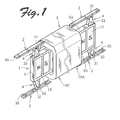
- Fig. 1 is a perspective view schematically showing the configuration of a linear motor according to an embodiment of the present invention.
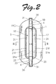
- Fig. 2 is a front view of the linear motor shown in Fig. 1 as viewed from the left side of Fig. 1 .
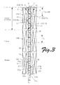
- Fig. 3 is a cross-sectional view taken along line III-III of Fig. 2 .
- cross-sectional portions are not hatched in Fig. 3 .
- the linear motor according to the embodiment includes a mover 1, a stator 3, four guide rails 2, and four casters 4.
- Fig. 1 is a perspective view schematically showing the configuration of a linear motor according to an embodiment of the present invention.
- Fig. 2 is a front view of the linear motor shown in Fig. 1 as viewed from the left side of Fig. 1 .
- Fig. 3 is a cross-sectional view taken along line III-III of Fig. 2 .
- cross-sectional portions are not hatched in Fig. 3 .
- the mover 1 includes a rectangular frame member 5 and a permanent magnet array 9 disposed inside the frame member 5.
- the permanent magnet array 9 is fixed inside the frame member 5 using a molding material 6 (see Fig. 3 ) made of a non-magnetie material such as aluminum or a synthetic resin.
- a molding material 6 made of a non-magnetie material such as aluminum or a synthetic resin.
- the frame member 5 may be formed by insert molding with a plurality of permanent magnets 13 forming the permanent magnet array 9 embedded as inserts.
- the molding material is aluminum.
- the plurality of permanent magnets 13 forming the permanent magnet array 9 are magnetized in a perpendicular direction perpendicular to a motion direction of the mover 1 such that magnetic poles having different polarities alternately appear on magnetic pole surfaces of the plurality of permanent magnets 13 in the motion direction.
- the magnetic pole surfaces of the plurality of permanent magnets 13 forming the permanent magnet array 9 are exposed on both sides in the perpendicular direction discussed earlier.
- the permanent magnet array 9 is thus formed by the plurality of permanent magnets 13 arranged in an array in the motion direction of the mover 1.
- the casters 4 are fixed at the four corners of the frame member 5 at opposite positions in the vertical direction in Fig. 1 .
- the casters 4 are each formed by a roller 31 and a roller support portion 33 that rotatably supports the roller 31.
- the roller support portion 33 is fixed at both ends of a pair of opposite surfaces 5a of the frame member 5 that extend in the motion direction.
- the guide rails 2 each include a groove 35 and have a U-shaped cross section.
- the guide rails 2 are fixed to fixation portions (not shown) such that a pair of guide rails 2 are disposed on each side of the stator 3 to extend in the motion direction of the mover 1.
- Each pair of guide rails 2 are disposed such that their grooves 35 face each other.
- the rollers 31 of the casters 4 are inserted into the grooves 35 of the guide rails 2.
- the mover 1 is thus supported by the four guide rails 2 to be reciprocally movable.
- the stator 3 includes a first magnetic pole portion array 15, a second magnetic pole portion array 17, and three excitation windings 19A to 19C.
- the first and second magnetic pole portion arrays 15 and 17 each include a plurality of magnetic pole portions 21 disposed on both sides of the permanent magnet array 9 in the perpendicular direction which is perpendicular to the motion direction.
- Each magnetic pole portion 21 is formed from iron, which is a magnetic material or a magnetically permeable material, and has a thin plate-like shape. Magnetic pole portions 21 located in the lower region of Fig. 3 are described with individual reference symbols provided to their respective portions.
- the magnetic pole portions 21 each include a magnetic pole surface 21e that faces the permanent magnet array 9 with a narrow gap therebetween, and an opposed surface 21f opposite the magnetic pole surface 21e and located on the side of the excitation winding 19C.
- a pair of inclined surfaces 21 g that are inclined away from the excitation winding 19C from the center side toward the end side of each magnetic pole portion 21 are formed at both end portions of each opposed surface 21f in the motion direction.
- the magnetic pole surfaces 21e of the plurality of magnetic pole portions 21 of the first magnetic pole portion array 15 face a magnetic pole surface 9a of the permanent magnet array 9 on one side.
- the magnetic pole surfaces 21e of the plurality of magnetic pole portions 21 of the second magnetic pole portion array 17 face a magnetic pole surface 9b of the permanent magnet array 9 on the other side.
- the plurality of magnetic pole portions 21 and the excitation windings 19A to 19C are molded with an insulating resin 23 (indicated by the dotted area) made of an epoxy resin such that the magnetic pole surfaces 21e of the plurality of magnetic pole portions 21 are exposed.
- the first and second magnetic pole portion arrays 15 and 17 and the permanent magnet array 9 are configured such that the relationship of ⁇ p ⁇ TL ⁇ 2 ⁇ p is established.
- Two (p) magnetic pole portions 21 included in the first magnetic pole portion array 15 and two (q) magnetic pole portions 21 included in the second magnetic pole portion array 17, excited by each of the excitation windings (19A to 19C), are disposed such that respective end portions of the magnetic pole portions face each other across the mover 1, and such that the magnetic pole portions 21 included in one magnetic pole portion array are shifted (displaced in position) in the motion direction with respect to the magnetic pole portions 21 included in the other.
- the plurality of magnetic pole portions included in the first magnetic pole portion array 15 are shifted with respect to the plurality of magnetic pole portions included in the second magnetic pole portion array 17 in the motion direction by the pitch ⁇ p between the centers of the permanent magnets 13.
- the number (p) of the magnetic pole portions 21 included in the first magnetic pole portion array 15 is equal to the number (q) of the magnetic pole portions 21 included in the second magnetic pole portion array 17.
- the three excitation windings 19A to 19C are disposed in line in the motion direction of the reciprocating motion, and formed by excitation windings for three phases (n phases) that excite the plurality of magnetic pole portions 21.
- the three excitation windings 19A to 19C excite the plurality of magnetic pole portions 21 with U-phase, V-phase, and W-phase, which are shifted from each other by an electrical angle of 120° (360°/3).
- the pitch between the centers of two permanent magnets 13 is defined as ⁇ p
- the pitch between adjacent two of the excitation windings 19A to 19C is (r ⁇ 1/3) ⁇ p.
- r may be an integer of one or more, and is an integer of three to ten in consideration of practicality.
- Each of the excitation windings 19A to 19C is hollow-structured by winding a winding conductor into a coil such that two magnetic pole portions 21 included in the first magnetic pole portion array 15 and two magnetic pole portions 21 included in the second magnetic pole portion array 17 are located in an internal space of the coil and are excited by the corresponding one of the excitation windings.
- the excitation windings 19A to 19C have a hollow structure in a shape similar to an oval in which a portion of the excitation windings 19A to 19C extends in parallel to the opposed surfaces 21f of the magnetic pole portions 21.
- the mover 1 is disposed between the first magnetic pole portion array 15 and the second magnetic pole portion array 17 disposed inside the excitation windings 19A to 19C.
- one magnetic pole portion 21 of the two magnetic pole portions 21 included in the first magnetic pole portion array 15 and excited by each of the excitation windings (19A to 19C) (the upper magnetic pole portion 21 in each excitation winding in Fig. 3 ) is disposed such that one end portion of the magnetic pole portion 21 projects out of the corresponding one of the excitation windings.
- one magnetic pole portion 21 of the two magnetic pole portions 21 included in the second magnetic pole portion array 17 and excited by each of the excitation windings is disposed such that one end portion of the magnetic pole portion 21 projects out of the corresponding one of the excitation windings.
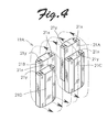
- Fig. 4 in a state in which a current flows through the excitation winding 19A (U-phase) in one direction (in the embodiment, the counterclockwise direction as seen from the left side of Fig. 4 ), for example, end portions 21x on one side of two magnetic pole portions 21A and 21B forming the first magnetic pole portion array 15 and two magnetic pole portions 21C and 21D forming the second magnetic pole portion array 17, surrounded by the excitation winding 19A, form the south pole, and end portions 21y on the other side of the magnetic pole portions 21A, 21B, 21C, and 21D form the north pole.
- the polarity (south pole) of the end portions 21x of the magnetic pole portions 21A and 21B on one side and the polarity (north pole) of the end portions 21y of the magnetic pole portions 21C and 21D on the other side are different from each other, the end portions 21x and the end portions 21y facing each other.
- Fig. 3 as indicated by the arrow Al
- a current flows through the excitation winding 19B (V-phase) and the excitation winding 19C (W-phase) in the opposite direction to the current which flows through the excitation winding 19A (U-phase), and magnetic flux flows through the magnetic pole portions 21 surrounded by the excitation windings 19B and 19C in a meandering manner in the opposite direction to the magnetic flux which flows through the magnetic pole portions 21A to 21D surrounded by the excitation winding 19A.
- the magnetic pole portions 21 and the permanent magnet array 9 are attracted toward and repulsed from each other to move the mover 1 in the direction from the excitation winding 19C toward the excitation winding 19A (upward in Fig. 5 ) by the pitch between adjacent permanent magnets 13 ( ⁇ p) as shown in Fig. 5 .
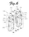
- a current flows through the excitation winding 19A in the opposite direction to the example shown in Fig. 4 (in the clockwise direction as seen from the left side of Fig. 6 ).
- each of the excitation windings (19A to 19C) is hollow-structured by winding a winding conductor into a coil such that two magnetic pole portions 21 included in the first magnetic pole portion array 15 and two magnetic pole portions 21 included in the second magnetic pole portion array 17 are located in an internal space of the coil and are excited by the corresponding one of the excitation windings. Therefore, most of the magnetic flux produced by the excitation windings (19A to 19C) directly flows through the two magnetic pole portions 21 included in the first magnetic pole portion array 15 and the two magnetic pole portions 21 included in the second magnetic pole portion array 17. Therefore, the maximum driving force for a motor size may be enhanced by increasing the amount of windings in excitation windings without significantly increasing the magnetic resistance. Also, the magnetic pole portions 21 may be formed to be small. This may reduce the amount of iron used, and hence the size of the linear motor.
- the mover 1 is supported by the four guide rails 2 using the four casters 4.
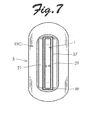
- the mover 1 may be supported with respect to the stator 3 using a molded member 37 made of a resin having a slidability and a wear resistance such as a polyacetal or a polyphenol as shown in Fig. 7 .
- the molded member 37 is located between and joined to the first and second magnetic pole portion arrays located inside the excitation windings 19A to 19C. That is, the molded member 37 is fixed to the side of the stator 3 by a resin molding material M.
- the molded member 37 slidably supports the permanent magnet array 9.
- the mover 1 is slidably supported with respect to the stator 3 by the molded member 37.
- a retention structure may be provided at both ends of the permanent magnet array 9.
- the resin having a slidability and a wear resistance and used to form the molded member 37 include Delrin available from DuPont.
- the molded member 37 may be fixed on the side of the mover 1, that is, to the outer side of the permanent magnet array 9.
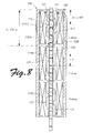
- Fig. 8 is a schematic view showing the configuration of a linear motor according to another embodiment of the present invention.
- Fig. 9 is a front view of the linear motor shown in Fig. 8 as viewed from the lower side of Fig. 8 .
- the linear motor according to the embodiment has the same structure as the linear motor shown in Figs. 1 to 6 , except that a stator 103 is provided with a pair of back yoke members 125A and 125B that form a back yoke. Therefore, component parts that are the same as those shown in Figs. 1 to 6 are denoted by reference numerals obtained by adding 100 to the reference numerals affixed to their counterparts in Figs. 1 to 6 to omit their descriptions.
- the back yoke members 125A and 125B each have a plate-like shape, and are formed from iron, which is a magnetic material, and disposed radially outwardly of excitation windings 119A to 119C.
- the back yoke members 125A and 125B are located on both sides of the excitation windings 119A to 119C to extend along first and second magnetic pole portion arrays 115 and 117.
- the back yoke member 125A faces the first magnetic pole portion array 115 across the excitation windings 119A to 119C
- the back yoke member 125B faces the second magnetic pole portion array 117 across the excitation windings 119A to 119C.
- a plurality of magnetic pole portions 121, the excitation windings 119A to 119C, and the back yoke members 125A and 125B are molded with an insulating resin 123 such as an epoxy resin.
- magnetic flux produced by the permanent magnet array 109 and the excitation windings 119A to 119C flows via the back yoke members 125A and 125B on the outer side of the excitation windings. Therefore, the rated driving force and the maximum driving force for a motor size can be further enhanced.
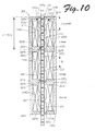
- Fig. 10 is a schematic view showing the configuration of a linear motor according to another embodiment of the present invention.
- Fig. 11 is a front view of the linear motor shown in Fig. 10 as viewed from the lower side of Fig. 10 .
- the linear motor according to the embodiment has the same structure as the linear motor shown in Figs. 8 and 9 , except that a stator 203 is provided with auxiliary yokes 227A to 227H. Therefore, component parts that are the same as those shown in Figs. 8 and 9 are denoted by reference numerals obtained by adding 100 to the reference numerals affixed to their counterparts in Figs. 8 and 9 to omit their descriptions.
- the auxiliary yokes 227A to 227H each have a plate-like shape, and are formed from iron, which is a magnetic material, and disposed on both outer sides of each of the excitation windings (219A to 219C) in the motion direction. End portions 227x of the auxiliary yokes 227A to 227D on one side are coupled to a back yoke member 225A so that the auxiliary yokes 227A to 227D extend from the back yoke member 225A toward a plurality of magnetic pole portions 221 forming the first magnetic pole portion array 215.
- End portions 227y of three auxiliary yokes 227A to 227C of the auxiliary yokes 227A to 227D on the other side are respectively connected to end portions of the magnetic pole portions 221 of the first magnetic pole portion array 215 that project out of the excitation windings (219A to 219C). Meanwhile, end portions 227x of the auxiliary yokes 227E to 227H on one side are coupled to a back yoke member 225B so that the auxiliary yokes 227E to 227H extend from the back yoke member 225B toward a plurality of magnetic pole portions 221 forming the second magnetic pole portion array 217.
- End portions 227y of three auxiliary yokes 227F to 227H of the auxiliary yokes 227E to 227H on the other side are respectively connected to end portions of the magnetic pole portions 221 of the second magnetic pole portion array 217 that project out of the excitation windings (219A to 219C).
- the auxiliary yokes 227A and 227B are taken as examples for description.
- Magnetic flux is produced by the permanent magnet array 209 and the excitation winding 219A, and passes through the magnetic pole portions 221 of the first and second magnetic pole portion arrays 215 and 217 excited by the excitation winding 219A.
- the magnetic flux flows through the auxiliary yokes 227A and 227B.
- magnetic flux produced by the permanent magnet array 209 and the excitation windings 219A to 219C flows via the back yoke members 225A and 225B on the outer side of the excitation windings, and the magnetic flux flows via the auxiliary yokes 227A to 227H on both outer sides of each of the excitation windings (219A to 219C) in the motion direction. Therefore, the rated driving force and the maximum driving force for a motor size can be further enhanced.
- the stator 3 includes an armature and the mover 1 includes a permanent magnet array 9.
- the stator may include a permanent magnet array and the mover may include an armature.
- the number (p) of the magnetic pole portions included in the first magnetic pole portion array and the number (q) of the magnetic pole portions included in the second magnetic pole portion array are equal to each other and are both two.
- the number (p) of the magnetic pole portions included in the first magnetic pole portion array and the number (q) of the magnetic pole portions included in the second magnetic pole portion array may be selected to be any number of one or more.
- the number (p) of the magnetic pole portions included in the first magnetic pole portion array may be different from the number (q) of the magnetic pole portions included in the second magnetic pole portion array.
Landscapes
- Engineering & Computer Science (AREA)
- Physics & Mathematics (AREA)
- Chemical & Material Sciences (AREA)
- Combustion & Propulsion (AREA)
- Electromagnetism (AREA)
- Power Engineering (AREA)
- Linear Motors (AREA)
Applications Claiming Priority (2)
| Application Number | Priority Date | Filing Date | Title |
|---|---|---|---|
| JP2009001461 | 2009-01-07 | ||
| JP2009253025A JP5484861B2 (ja) | 2009-01-07 | 2009-11-04 | リニアモータ |
Publications (2)
| Publication Number | Publication Date |
|---|---|
| EP2207256A2 true EP2207256A2 (fr) | 2010-07-14 |
| EP2207256A3 EP2207256A3 (fr) | 2016-05-11 |
Family
ID=41682729
Family Applications (1)
| Application Number | Title | Priority Date | Filing Date |
|---|---|---|---|
| EP10275001.5A Withdrawn EP2207256A3 (fr) | 2009-01-07 | 2010-01-06 | Moteur linéaire |
Country Status (6)
| Country | Link |
|---|---|
| US (1) | US8198760B2 (fr) |
| EP (1) | EP2207256A3 (fr) |
| JP (1) | JP5484861B2 (fr) |
| KR (1) | KR20100081936A (fr) |
| CN (1) | CN101771323B (fr) |
| TW (1) | TWI459684B (fr) |
Cited By (2)
| Publication number | Priority date | Publication date | Assignee | Title |
|---|---|---|---|---|
| ITRM20120425A1 (it) * | 2012-08-31 | 2014-03-01 | Claudio Bruzzese | Attuatore lineare elettromagnetico e relativo giunto prismatico rotoidale per azionamenti diretti |
| EP2320543A3 (fr) * | 2009-11-09 | 2016-11-23 | Sanyo Denki Co., Ltd. | Appareil de machine électrique |
Families Citing this family (18)
| Publication number | Priority date | Publication date | Assignee | Title |
|---|---|---|---|---|
| TWI460966B (zh) * | 2009-01-23 | 2014-11-11 | Hitachi Metals Ltd | Moving elements and linear motors |
| US20120280579A1 (en) * | 2011-05-06 | 2012-11-08 | Bose Corporation | Linear moving magnet motor cogging force ripple reducing |
| JP5750340B2 (ja) * | 2011-09-05 | 2015-07-22 | 山洋電気株式会社 | 電気機械 |
| CN102361387A (zh) * | 2011-10-28 | 2012-02-22 | 雅科贝思精密机电(上海)有限公司 | 一种定位负载的直线电机 |
| JP5750358B2 (ja) * | 2011-10-28 | 2015-07-22 | 山洋電気株式会社 | 電気機械 |
| JPWO2014192058A1 (ja) * | 2013-05-27 | 2017-02-23 | 株式会社安川電機 | リニアモータ及びステージ装置 |
| CN103939574B (zh) * | 2014-03-13 | 2016-08-24 | 都佳宜电器制品(深圳)有限公司 | 声波马达 |
| JP6052259B2 (ja) * | 2014-09-18 | 2016-12-27 | 株式会社安川電機 | 直動回転アクチュエータ |
| CN107108166B (zh) * | 2014-12-23 | 2019-05-10 | 奥的斯电梯公司 | 具有线性驱动的电梯系统 |
| CN114825841A (zh) | 2017-06-30 | 2022-07-29 | 日本电产三协株式会社 | 致动器 |
| CN107579643B (zh) * | 2017-11-03 | 2019-08-09 | 中国矿业大学 | 一种单相圆筒型永磁直线电机二维磁路建模方法 |
| CN111819645B (zh) | 2018-04-16 | 2022-06-28 | 科韦里有限公司 | 磁铁模块制造方法 |
| WO2019240132A1 (fr) * | 2018-06-12 | 2019-12-19 | キヤノン株式会社 | Moteur linéaire, dispositif de transport et dispositif de production |
| CN110661396A (zh) * | 2018-06-29 | 2020-01-07 | 河南东迪电气有限公司 | 一种直线发电装置 |
| CN113211488B (zh) * | 2020-02-04 | 2022-07-29 | 广东博智林机器人有限公司 | 抓取装置 |
| CN111168713B (zh) * | 2020-02-17 | 2021-10-08 | 广东博智林机器人有限公司 | 电磁推进机构及夹料装置 |
| CN115839472B (zh) * | 2022-12-28 | 2026-01-06 | 西安交通大学城市学院 | 一种武术动作分析用摄影装置 |
| WO2025209837A1 (fr) * | 2024-04-04 | 2025-10-09 | Gea Mechanical Equipment Italia S.P.A. | Machine vernier linéaire |
Citations (1)
| Publication number | Priority date | Publication date | Assignee | Title |
|---|---|---|---|---|
| JP3906443B2 (ja) | 1999-05-07 | 2007-04-18 | 株式会社日立製作所 | リニアモータ |
Family Cites Families (19)
| Publication number | Priority date | Publication date | Assignee | Title |
|---|---|---|---|---|
| US4254350A (en) * | 1979-07-12 | 1981-03-03 | Miroshnichenko Vitaly T | Asynchronous line-fed motor |
| CN1005441B (zh) * | 1985-04-01 | 1989-10-11 | 西安工业自动化仪表研究所 | 电子换向直线电机 |
| JPH01160348A (ja) * | 1987-12-15 | 1989-06-23 | Tokyo Electric Co Ltd | リニアパルスモータ |
| JP2651734B2 (ja) * | 1990-02-19 | 1997-09-10 | 宇宙開発事業団 | 電磁アクチュエータ |
| US5396140A (en) * | 1993-05-28 | 1995-03-07 | Satcon Technology, Corp. | Parallel air gap serial flux A.C. electrical machine |
| JPH07336967A (ja) * | 1994-06-03 | 1995-12-22 | Yaskawa Electric Corp | 軸方向空隙形同期モータ |
| JPH08317626A (ja) * | 1995-05-19 | 1996-11-29 | Honda Motor Co Ltd | 円筒形リニアモータ及び円筒形リニアモータの製造方法 |
| EP1020013B1 (fr) * | 1997-10-04 | 2004-04-28 | Z & D Limited | Compresseur a moteur lineaire |
| JP3395155B2 (ja) | 1999-05-07 | 2003-04-07 | 株式会社日立製作所 | リニアモータ及びその製造方法 |
| JP2002171743A (ja) * | 2000-12-05 | 2002-06-14 | Showa Electric Wire & Cable Co Ltd | リニアモータ |
| JP3717436B2 (ja) * | 2001-03-30 | 2005-11-16 | 山洋電気株式会社 | シリンダ型リニア同期モータ |
| US6936937B2 (en) * | 2002-06-14 | 2005-08-30 | Sunyen Co., Ltd. | Linear electric generator having an improved magnet and coil structure, and method of manufacture |
| US6822581B2 (en) * | 2002-10-16 | 2004-11-23 | Marian Chaffe | Traffic signal with adjustable cycles |
| JP2004215437A (ja) * | 2003-01-07 | 2004-07-29 | Fuji Electric Holdings Co Ltd | リニアアクチュエータ |
| JP2005245108A (ja) * | 2004-02-25 | 2005-09-08 | Mitsubishi Heavy Ind Ltd | リニアモータ |
| JP4708093B2 (ja) * | 2005-06-01 | 2011-06-22 | 山洋電気株式会社 | リニアモータ |
| JP4429228B2 (ja) * | 2005-07-25 | 2010-03-10 | キヤノン株式会社 | 駆動装置 |
| JP4710838B2 (ja) * | 2007-01-24 | 2011-06-29 | セイコーエプソン株式会社 | ブラシレスdcモータ |
| JP2008245399A (ja) * | 2007-03-27 | 2008-10-09 | Mitsubishi Electric Corp | シャフト型リニアモータの電機子、シャフト型リニアモータ、及びシャフト型リニアモータの電機子の製造方法 |
-
2009
- 2009-11-04 JP JP2009253025A patent/JP5484861B2/ja active Active
-
2010
- 2010-01-05 KR KR1020100000378A patent/KR20100081936A/ko not_active Withdrawn
- 2010-01-06 US US12/683,161 patent/US8198760B2/en not_active Expired - Fee Related
- 2010-01-06 EP EP10275001.5A patent/EP2207256A3/fr not_active Withdrawn
- 2010-01-07 TW TW099100285A patent/TWI459684B/zh not_active IP Right Cessation
- 2010-01-07 CN CN201010002029.5A patent/CN101771323B/zh not_active Expired - Fee Related
Patent Citations (1)
| Publication number | Priority date | Publication date | Assignee | Title |
|---|---|---|---|---|
| JP3906443B2 (ja) | 1999-05-07 | 2007-04-18 | 株式会社日立製作所 | リニアモータ |
Cited By (2)
| Publication number | Priority date | Publication date | Assignee | Title |
|---|---|---|---|---|
| EP2320543A3 (fr) * | 2009-11-09 | 2016-11-23 | Sanyo Denki Co., Ltd. | Appareil de machine électrique |
| ITRM20120425A1 (it) * | 2012-08-31 | 2014-03-01 | Claudio Bruzzese | Attuatore lineare elettromagnetico e relativo giunto prismatico rotoidale per azionamenti diretti |
Also Published As
| Publication number | Publication date |
|---|---|
| CN101771323A (zh) | 2010-07-07 |
| JP5484861B2 (ja) | 2014-05-07 |
| TW201027881A (en) | 2010-07-16 |
| JP2010183823A (ja) | 2010-08-19 |
| KR20100081936A (ko) | 2010-07-15 |
| TWI459684B (zh) | 2014-11-01 |
| EP2207256A3 (fr) | 2016-05-11 |
| US8198760B2 (en) | 2012-06-12 |
| US20100171374A1 (en) | 2010-07-08 |
| CN101771323B (zh) | 2015-02-11 |
Similar Documents
| Publication | Publication Date | Title |
|---|---|---|
| EP2207256A2 (fr) | Moteur linéaire | |
| US8569916B2 (en) | Electrical machine apparatus | |
| EP1198055B1 (fr) | Moteur linéaire, ses systèmes de commande et d'entrainement et son procédé de fabrication | |
| US20090206686A1 (en) | Ring coil motor | |
| JP5421396B2 (ja) | 主歯及び副歯を有する鉄心コアを備える電動機 | |
| JP2003158866A (ja) | フォーサ及び三相リニアモータシステム | |
| JPH1143852A (ja) | 自動編み機のモータ組立体 | |
| KR101048055B1 (ko) | 코어에 슬릿을 형성한 횡자속 전기기기 | |
| JP5589507B2 (ja) | リニア駆動装置の可動子及び固定子 | |
| CN100527573C (zh) | 直线电动机和xy台 | |
| KR20240034878A (ko) | 모듈형 리니어 모터 | |
| JP4497986B2 (ja) | クローポール型三相リニアモータ | |
| KR100870448B1 (ko) | 횡자속 선형전동기 | |
| KR100360255B1 (ko) | 리니어 모터의 손실 저감구조 | |
| JP2010130843A (ja) | コアレスリニアモータ | |
| JP4475059B2 (ja) | リニア電動機 | |
| JP2007209175A (ja) | 三相リニアモータ | |
| JP2004215414A (ja) | リニアモータ | |
| JP6056570B2 (ja) | リニアモータ | |
| JPH08140330A (ja) | 可動磁石形リニアモータ | |
| KR20260038659A (ko) | 회전자 코어, 및 이를 포함하는 축 방향 자속 모터 | |
| JP2007209174A (ja) | 三相リニアモータ | |
| JP5589508B2 (ja) | リニア駆動装置の可動子、固定子、及びリニア駆動装置 | |
| JP2005057822A (ja) | リニアモータ | |
| JP2007209176A (ja) | 三相リニアモータ |
Legal Events
| Date | Code | Title | Description |
|---|---|---|---|
| PUAI | Public reference made under article 153(3) epc to a published international application that has entered the european phase |
Free format text: ORIGINAL CODE: 0009012 |
|
| AK | Designated contracting states |
Kind code of ref document: A2 Designated state(s): AT BE BG CH CY CZ DE DK EE ES FI FR GB GR HR HU IE IS IT LI LT LU LV MC MK MT NL NO PL PT RO SE SI SK SM TR |
|
| AX | Request for extension of the european patent |
Extension state: AL BA RS |
|
| PUAL | Search report despatched |
Free format text: ORIGINAL CODE: 0009013 |
|
| AK | Designated contracting states |
Kind code of ref document: A3 Designated state(s): AT BE BG CH CY CZ DE DK EE ES FI FR GB GR HR HU IE IS IT LI LT LU LV MC MK MT NL NO PL PT RO SE SI SK SM TR |
|
| AX | Request for extension of the european patent |
Extension state: AL BA RS |
|
| RIC1 | Information provided on ipc code assigned before grant |
Ipc: H02K 7/08 20060101ALN20160405BHEP Ipc: H02K 1/27 20060101ALN20160405BHEP Ipc: H02K 41/03 20060101AFI20160405BHEP |
|
| STAA | Information on the status of an ep patent application or granted ep patent |
Free format text: STATUS: THE APPLICATION HAS BEEN PUBLISHED |
|
| STAA | Information on the status of an ep patent application or granted ep patent |
Free format text: STATUS: THE APPLICATION IS DEEMED TO BE WITHDRAWN |
|
| 18D | Application deemed to be withdrawn |
Effective date: 20161112 |