EP2207364B1 - Composant doté d'une structure de microphone micromécanique - Google Patents
Composant doté d'une structure de microphone micromécanique Download PDFInfo
- Publication number
- EP2207364B1 EP2207364B1 EP09177681.5A EP09177681A EP2207364B1 EP 2207364 B1 EP2207364 B1 EP 2207364B1 EP 09177681 A EP09177681 A EP 09177681A EP 2207364 B1 EP2207364 B1 EP 2207364B1
- Authority
- EP
- European Patent Office
- Prior art keywords
- diaphragm
- layer
- counter element
- component
- structured
- Prior art date
- Legal status (The legal status is an assumption and is not a legal conclusion. Google has not performed a legal analysis and makes no representation as to the accuracy of the status listed.)
- Active
Links
Images




Classifications
-
- H—ELECTRICITY
- H04—ELECTRIC COMMUNICATION TECHNIQUE
- H04R—LOUDSPEAKERS, MICROPHONES, GRAMOPHONE PICK-UPS OR LIKE ACOUSTIC ELECTROMECHANICAL TRANSDUCERS; ELECTRIC HEARING AIDS; PUBLIC ADDRESS SYSTEMS
- H04R1/00—Details of transducers, loudspeakers or microphones
- H04R1/20—Arrangements for obtaining desired frequency or directional characteristics
- H04R1/32—Arrangements for obtaining desired frequency or directional characteristics for obtaining desired directional characteristic only
- H04R1/34—Arrangements for obtaining desired frequency or directional characteristics for obtaining desired directional characteristic only by using a single transducer with sound reflecting, diffracting, directing or guiding means
- H04R1/38—Arrangements for obtaining desired frequency or directional characteristics for obtaining desired directional characteristic only by using a single transducer with sound reflecting, diffracting, directing or guiding means in which sound waves act upon both sides of a diaphragm and incorporating acoustic phase-shifting means, e.g. pressure-gradient microphone
-
- H—ELECTRICITY
- H04—ELECTRIC COMMUNICATION TECHNIQUE
- H04R—LOUDSPEAKERS, MICROPHONES, GRAMOPHONE PICK-UPS OR LIKE ACOUSTIC ELECTROMECHANICAL TRANSDUCERS; ELECTRIC HEARING AIDS; PUBLIC ADDRESS SYSTEMS
- H04R19/00—Electrostatic transducers
- H04R19/01—Electrostatic transducers characterised by the use of electrets
- H04R19/016—Electrostatic transducers characterised by the use of electrets for microphones
-
- H—ELECTRICITY
- H04—ELECTRIC COMMUNICATION TECHNIQUE
- H04R—LOUDSPEAKERS, MICROPHONES, GRAMOPHONE PICK-UPS OR LIKE ACOUSTIC ELECTROMECHANICAL TRANSDUCERS; ELECTRIC HEARING AIDS; PUBLIC ADDRESS SYSTEMS
- H04R31/00—Apparatus or processes specially adapted for the manufacture of transducers or diaphragms therefor
Definitions
- the invention relates to a component having a micromechanical microphone structure, comprising at least a deflectable by the sound pressure first membrane, which acts as a deflectable electrode, a fixed acoustically permeable counter element, which acts as a counter electrode, and a further capacitance for evaluating the capacitance changes between the first deflectable electrode and the counter electrode.
- the invention further relates to a method for producing such a component.
- MEMS micro-electro-mechanical system
- the sound pressure is usually detected in the form of a capacitance change between an acoustically active membrane and a substantially rigid counter electrode.
- An evaluation concept for this type of microphones in which the capacitance change can be determined with a relatively low voltage between the membrane and the counterelectrode, is based on a comparison of the capacitance change with a fixed reference capacitance.
- this reference capacitance is located on the same component as the measuring capacitance.
- a micromechanical pressure sensor in which a capacitive detection is realized by means of a counter-element over a cavity and a membrane arranged above the counter-element.
- a very space-saving micromechanical microphone structure with a measuring capacity and a reference capacity which has a high sensitivity in relation to their small size.
- the fixed counter element between the deflectable first membrane and a second membrane is arranged.
- the fixed counter element not only functions as a counterelectrode for the deflectable first diaphragm but also forms an electrode of the further capacitance, while the second diaphragm forms the second electrode of this further capacitance.
- the measuring capacity and the further capacity are therefore one above the other, realized with a common center electrode.
- This electrode arrangement is not only very space-saving, but also allows different Ausensejane, depending on whether it is to act in the other capacity to a constant reference capacity or a sound pressure-dependent capacity.
- the fixed counter element and the second diaphragm are mechanically coupled but electrically insulated from each other so that they form a constant reference capacitance.
- the reference capacitance thus consumes no additional component surface but is arranged within the active microphone surface.
- the known from the prior art evaluation concept can be easily applied.
- the further capacity also changes under the effect of the sound pressure, i. although the second membrane is deflected under the action of sound pressure.
- the counter element according to the invention is arranged between the two membranes and forms a fixed electrode for both the measuring capacity and for the further capacity, the measuring capacity and the further capacity change in the same direction deflection of the two membranes in opposite directions.
- the measurement signal can be amplified simply by combining the two capacitances to increase the microphone sensitivity.
- the two membranes of the component according to the invention mechanically couple and electrically isolate against each other. In this case, it is sufficient if essentially only one of the two membranes is acoustically active, since the sound pressure is transmitted via the mechanical coupling directly to the other membrane.
- a mechanical coupling is not required if both membranes of the device are acoustically active. In this case, it is advantageous if the two membranes are acoustically active and acoustically permeable in mutually offset subregions, in order to avoid interactions.
- the membrane surfaces facing the counter element and / or the surfaces of the counter element are provided with a dielectric coating in order to avoid a short circuit of the measuring capacitance and / or the reference capacitance in overload situations.
- the microphone structure may comprise an overload protection in the form of stops which are formed in the surface of a deflectable membrane facing the counter element and / or in the surface of the counter element facing a deflectable membrane.
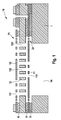
- Component 10 shown comprises a micromechanical microphone structure, which is formed in a layer structure over a substrate 1.
- This microphone structure consists essentially of two superposed membranes 11 and 12, between which a fixed counter-element 13 is arranged.
- the membrane 11 is electrically insulated via insulating layers 2 and 4 on the one hand against the substrate 1 and on the other hand against the counter-element 13.
- a further insulation layer 6 of the layer structure serves for the electrical insulation between the counter element 13 and the membrane 12.
- the two membranes 11 and 12 and the counter element 13 consist at least in regions of an electrically conductive material, such as a correspondingly doped polysilicon. In this way, the membrane 11 together with the counter-element 13 forms a first capacitance, while the membrane 12 together with the counter-element 13 forms a second capacitance.
- the counter element 13 is significantly thicker than the two membranes 11 and 12 and thus substantially rigid.
- 13 through holes 131, 132 are formed in the counter element, so that the counter element 13 is acoustically transparent.
- both membranes 11 and 12 are acoustically active in the embodiment described here. They are deflected independently of one another by the sound pressure, which acts on the membrane 12 starting from the component top side and acts on the membrane 11 via a sound opening 14 in the component rear side.
- Through openings 111 are formed in the middle region of the membrane 11 so that the membrane 11 is acoustically active substantially only in the closed edge area.
- this edge region of the membrane 12 is provided with passage openings 121, so that the membrane 12 substantially only in the closed central region is acoustically active.
- This staggered arrangement of the through openings 111 and 121 or the acoustically active areas of the membranes 11 and 12 serves to avoid interactions between the two membranes 11 and 12. Due to the through holes 111, 121 and 131, 132 in the membranes 11 and 12 and in the Counter-element 13 causes the sound pressure in the same direction deflection of the two membranes 11 and 12. Since the counter-element 13 sandwich-like disposed between the two membranes 11 and 12, the first and second capacitance change in opposite directions. The evaluation takes place here by difference formation between the first and second capacity
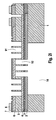
- the manufacturing method starts from a substrate 1, such as a silicon wafer.
- a first sacrificial layer 2 is first deposited and patterned.
- Fig. 2a shows the layer structure after the structuring of the first sacrificial layer 2, in which openings 21 were generated, which communicate with the through-openings 111 to be generated in the first membrane 11.
- the first sacrificial layer 2 also acts as the first insulating layer 2. Typically, this is a thermal oxide or a TEOS oxide.
- a first membrane layer 3 in the form of a polysilicon layer is deposited and doped.
- Fig. 2b shows the layer structure, after the structuring of the membrane layer 3, in which not only the through holes 111 were generated but also a spring suspension 31 was formed for the membrane 11 to promote membrane deflections.
- a second sacrificial layer 4 is deposited and patterned.
- openings 41 were generated which communicate with the passage openings 111 in the first membrane layer 3.
- an opening 42 was created, which is required for the realization of the electrical contacts of the individual capacitor electrodes of the device 10. This situation is in Fig. 2c shown. Since the second sacrificial layer 4 in the context of the device 10 acts as an insulating layer can these - like the first sacrificial layer 2 - are formed by a thermal oxide or a TEOS oxide.
- an at least partially electrically conductive layer 5 is applied, from which the fixed counter-element 13 is formed.
- a thicker epi-polysilicon layer 5 was produced and doped on the second sacrificial layer 4.
- This epi-polysilicon layer 5 has not been patterned at least in the membrane region, so that the polysilicon of this layer 5 fills out the structuring of the underlying layers 4, 3 and 2, which is due to Fig. 2d is illustrated.
- a polysilicon starter layer is typically deposited first before an epi-polysilicon layer is then deposited thereon. This epi-polysilicon is doped and can be planarized for better processing.
- the fixed counter element can also be realized in a thinner polysilicon layer, which is stiffer than the two membranes in the layer structure suspended.
- Another possibility is to realize the counter element in the form of a layer stack of polysilicon and oxide or nitride, which is under tensile stress. In this way it can also be achieved that the counter element reacts significantly less to sound waves than the membranes.
- a third sacrificial layer 6 was deposited, which also acts as an insulating layer in the context of the device 10. During the structuring of this sacrificial layer 6, openings 61 were generated which communicate with the openings 121 to be produced in the second membrane 12 of the component 10. In addition, an opening 62 was created, which is required for the realization of electrical contacts.
- Fig. 2e shows the layer structure with the structured third sacrificial layer 6.
- a second membrane layer 7 in the form of a further polysilicon layer was deposited, doped and patterned on the third sacrificial layer 6, a spring-like diaphragm suspension 71 being produced here as well next to the passage openings 121.
- the resulting layer structure is in Fig. 2f shown.
- the layer structure of the component 10 also comprises one or more structured metal layers 8.
- the metal layer 8 was applied to the second membrane layer 7 and structured, which is described in US Pat Fig. 2g is shown before the counter element or the epi-polysilicon layer 5 has been patterned and etching accesses were made to the sacrificial layers 2, 4 and 6 to expose the microphone structure.
- the metal layer 8 for the realization of electrical contacts can also be generated at a later time.
- the through-openings 121 in the second membrane layer 7, which continue in the openings 61 in the third sacrificial layer 6, have now been transferred into the epi-polysilicon layer 5, around the through-openings 131 in the edge region of the counter element 13 to produce.
- the second sacrificial layer 4 serves as ⁇ tzstoppgrenze.
- the result of this first step of trenching is in the form of trench trenches 91 in FIG Fig. 2h shown.
- the sound opening 14 is first generated, which forms the rear side volume of the microphone structure.
- This trench process stops at the first sacrificial layer 2 and continues to be deeper only in the region in which the epi-polysilicon layer 5 directly adjoins the substrate surface, ie in the region of the through-openings 111 in the first membrane layer 3. In this region, the trench process stopped only when reaching the third sacrificial layer 6, so that in the central region of the counter element 13 passage openings 132 arise.
- the corresponding trench trenches 92 are in Fig. 2i to recognize.
- the trench trenches 91 and 92 in conjunction with the sound aperture 14 are used as ⁇ tzzu réelle to expose the two membranes 11 and 12, which takes place for example by means of HF or in a gas phase etching.
- the sacrificial layer material of the layers 2, 4 and 6 is removed in the regions below the first membrane 11 and between the counter element 13 and the two membranes 11 and 12.
- the resulting device structure is in Fig. 2j shown. This figure essentially corresponds to Fig. 1 ,
- the backside trench process can also be run before the front side trench process.
- a further sacrificial layer is deposited and patterned before the individual sacrificial layer deposits in order to realize defined stops for the deflectable electrodes of the microphone structure.
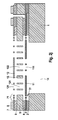
- a device 30 is in Fig. 3 shown.
- the component 30 differs from that in FIG Fig. 1 shown component 10 only by stops 122 and 133 which are formed on the underside of the second diaphragm 12 and the counter-element 13.
- the stops 122 and 133 form the contact surfaces between the electrodes of the microphone structure. The smaller these contact surfaces, the lower the adhesive force between the electrodes and, accordingly, the force required to bring the membranes 11 and 12 back to their original position.
- the stops 122 and 133 also consist of a dielectric material or at least are coated with such, so that they prevent a short circuit of the first and / or second capacitance in overload situations.
- a dielectric layer can be deposited before or after the sacrificial layer deposition, which advantageously has a significantly lower etching rate than the sacrificial layer, such as SiN or silicon-rich nitride.
- the adhesive force between SiN and Si is so low that the membranes can easily be brought back to their original position after overload situations.
- the stops 122 are formed on the outer edge of the acoustically active region of the second membrane 12.
- the stops 133 extend in extension from the counter element 13 in the direction of the first diaphragm 11, along the inner edge of the acoustically active region of the first diaphragm 11. In this way wear the stops 122 and 133 also to reduce the acoustic short circuit between the offset acoustically active and transparent membranes 11 and 12 at.
- Fig. 4 shows a component 50 with a micromechanical microphone structure
- the invention comprises two superposed membranes 51 and 52, between which a fixed counter-element 53 is arranged.
- the two membranes 51 and 52 are suspended in each case via a spring suspension 31 and 71 in the layer structure of the component 50 in order to favor their deflection.
- the membrane 51 is electrically insulated via insulating layers 2 and 4 on the one hand against the substrate 1 and on the other hand against the counter element 53.
- a further insulation layer 6 of the layer structure serves for electrical insulation between the counter element 53 and the membrane 52.
- the two membranes 51 and 52 and the counter element 53 at least partially consist of an electrically conductive material, such as a correspondingly doped polysilicon. In this way, the membrane 51 together with the counter-element 53 forms a first capacitance, while the membrane 52 together with the counter-element 53 forms a second capacitance.
- the counter-element 53 here is significantly thicker than the two membranes 51 and 52 and has first passage openings 531, so that it is substantially rigid and acoustically transparent. In order to achieve that the counter element reacts much less on sound waves than the membranes, but the counter element can also be realized in a thinner polysilicon layer, which is stiffer than the two membranes suspended in the layer structure. Another possibility is to realize the counter element in the form of a layer stack of polysilicon and oxide or nitride, which is under tensile stress.
- second passage openings 532 are formed for connecting webs 55, via which the two diaphragms 51 and 52 are mechanically coupled.
- the first diaphragm 51 is largely closed and thus acoustically active, while the entire microphone surface of the second diaphragm 52 is provided with passage openings 521, so that the second diaphragm 52 is acoustically at most low active.
- the mechanical coupling between the two membranes 51 and 52 causes both membranes 51 and 52 are deflected in the same direction, when the first Membrane 51 is acted upon via the sound opening 54 in the back of the component with sound pressure. Accordingly, as in the case of the component 10, the first and second capacitances change in opposite directions. The evaluation is also done here by subtraction between the first and second capacity.
Landscapes
- Engineering & Computer Science (AREA)
- Physics & Mathematics (AREA)
- Acoustics & Sound (AREA)
- Signal Processing (AREA)
- Health & Medical Sciences (AREA)
- Otolaryngology (AREA)
- Manufacturing & Machinery (AREA)
- Electrostatic, Electromagnetic, Magneto- Strictive, And Variable-Resistance Transducers (AREA)
Claims (8)
- Composant (10) présentant une structure micromécanique de microphone et comportant au moins :une première membrane (51) qui peut être déformée sous l'effet de la pression acoustique et qui fonctionne comme électrode déformable,un élément complémentaire (53) fixe et acoustiquement transparent, qui fonctionne comme électrode complémentaire etune autre capacité permettant d'évaluer les modifications de capacité entre la première électrode déformable (51) et l'électrode complémentaire (53),l'élément complémentaire fixe (53) étant disposé entre la première membrane déformable (51) et une deuxième membrane (52),l'élément complémentaire fixe (53) fonctionnant également comme électrode de l'autre capacité,la deuxième membrane (52) formant la deuxième électrode de l'autre capacité etl'autre capacité variant également sous l'effet de la pression acoustique,
caractérisé en ce queles deux membranes (51, 52) sont couplées mécaniquement l'une à l'autre mais sont électriquement isolées l'une de l'autre de telle sorte que les deux membranes (51, 52) soient déformées dans le même sens lorsque la pression acoustique agit sur la première membrane (51). - Composant selon la revendication 1, caractérisé en ce que la première membrane (51) est largement fermée et est ainsi acoustiquement active.
- Composant selon la revendication 1 ou 2, caractérisé en ce que la deuxième membrane (52) est pourvue d'ouvertures de passage (521) de telle sorte que la deuxième membrane (52) est en tout cas peu active acoustiquement.
- Composant selon l'une des revendications précédentes, caractérisé en ce que les deux capacités présentes se modifient dans des sens opposés lorsque les membranes sont déformées dans le même sens.
- Composant selon la revendication 1, caractérisé en ce que l'élément complémentaire fixe et la deuxième membrane sont couplés mécaniquement l'un à l'autre mais sont isolés électriquement l'un de l'autre de manière à former une capacité de référence constante.
- Composant selon l'une des revendications 1 ou 5, caractérisé en ce qu'au moins la surface des membranes tournée vers l'élément complémentaire et/ou la surface de l'élément complémentaire sont dotées d'un revêtement diélectrique.
- Composant (30) selon l'une des revendications 1, 5 ou 6, caractérisé en ce que la structure de microphone comporte une protection contre les surcharges qui présente la forme de butées (122, 132) qui sont formées dans la surface d'une membrane déformable (52) tournée vers l'élément complémentaire (53) et/ou dans la surface de l'élément complémentaire (53) tournée vers une membrane déformable (51).
- Procédé de fabrication d'un composant doté d'une structure micromécanique de microphone, en particulier de fabrication d'un composant (10) selon l'une des revendications 1 à 7, dans lequel la structure de membrane est réalisée par stratification au-dessus d'un substrat (1),
en appliquant sur la surface du substrat une première couche sacrifiée (2) électriquement isolante et en structurant cette dernière,
en formant au-dessus de la première couche sacrifiée (2) une première couche de membrane (3) dont au moins certaines parties sont électriquement conductrices et en structurant cette dernière,
en formant au-dessus de la première couche de membrane (3) une deuxième couche sacrifiée (4) électriquement isolante et en structurant cette dernière,
en formant au-dessus de la deuxième couche sacrifiée (4) une couche (5) dont au moins certaines parties sont électriquement conductrices pour réaliser un élément complémentaire fixe (13),
en appliquant au-dessus de la couche (5) une troisième couche sacrifiée (6) électriquement isolante et en structurant cette dernière,
en formant au-dessus de la troisième couche sacrifiée (6) une deuxième couche de membrane (7) dont au moins certaines parties sont électriquement conductrices et en structurant cette dernière,
en structurant la couche (5) par une opération de formation de tranchée sur le côté avant et/ou sur le côté arrière et en formant des accès de gravure vers la première, la deuxième et la troisième couche sacrifiée (2, 4, 6) et
en enlevant certaines parties de la première, de la deuxième et de la troisième couche sacrifiée (2, 4, 6) pour libérer une première membrane (51) dans la première couche de membrane (3), un élément complémentaire (53) dans la couche (5) et une deuxième membrane (52) dans la deuxième couche de membrane (7), caractérisé en ce que
les deux membranes (51, 52) sont couplées mécaniquement mais isolées électriquement l'une de l'autre.
Applications Claiming Priority (1)
| Application Number | Priority Date | Filing Date | Title |
|---|---|---|---|
| DE200910000053 DE102009000053A1 (de) | 2009-01-07 | 2009-01-07 | Bauelement mit einer mikromechanischen Mikrofonstruktur |
Publications (2)
| Publication Number | Publication Date |
|---|---|
| EP2207364A1 EP2207364A1 (fr) | 2010-07-14 |
| EP2207364B1 true EP2207364B1 (fr) | 2015-10-07 |
Family
ID=42103862
Family Applications (1)
| Application Number | Title | Priority Date | Filing Date |
|---|---|---|---|
| EP09177681.5A Active EP2207364B1 (fr) | 2009-01-07 | 2009-12-02 | Composant doté d'une structure de microphone micromécanique |
Country Status (2)
| Country | Link |
|---|---|
| EP (1) | EP2207364B1 (fr) |
| DE (1) | DE102009000053A1 (fr) |
Families Citing this family (5)
| Publication number | Priority date | Publication date | Assignee | Title |
|---|---|---|---|---|
| DE102009027873B4 (de) | 2009-07-21 | 2022-11-17 | Robert Bosch Gmbh | Mikromechanisches System und zugehöriges Herstellungsverfahren |
| WO2020097524A1 (fr) * | 2018-11-09 | 2020-05-14 | Knowles Electronics, Llc | Transducteur acoustique à amortissement réduit |
| CN109195075B (zh) * | 2018-11-29 | 2024-04-12 | 华景科技无锡有限公司 | 一种麦克风振膜及麦克风 |
| DE102019123077B4 (de) | 2019-08-28 | 2021-05-27 | Tdk Corporation | Verfahren zur Herstellung eines robusten Doppelmembranmikrofons |
| DE102023203446A1 (de) * | 2023-04-17 | 2024-10-17 | Robert Bosch Gesellschaft mit beschränkter Haftung | Mikroelektromechanisches akustisches Bauelement |
Family Cites Families (4)
| Publication number | Priority date | Publication date | Assignee | Title |
|---|---|---|---|---|
| DE2155026C3 (de) * | 1971-11-05 | 1974-05-30 | Sennheiser Electronic Dr.-Ing. Fritz Sennheiser, 3002 Wennebostel | Schaltungsanordnung zur Schaltung eines Niederfrequenzkondensatormikrofons |
| DE10316287B3 (de) | 2003-04-09 | 2004-07-15 | Siemens Audiologische Technik Gmbh | Richtmikrofon |
| JP4966370B2 (ja) * | 2006-03-30 | 2012-07-04 | パルス・エムイーエムエス・アンパルトセルスカブ | シングルダイ型mems音響トランスデューサおよび製造方法 |
| DE102006024668A1 (de) | 2006-05-26 | 2007-11-29 | Robert Bosch Gmbh | Mikromechanisches Bauelement und Verfahren zu dessen Herstellung |
-
2009
- 2009-01-07 DE DE200910000053 patent/DE102009000053A1/de not_active Withdrawn
- 2009-12-02 EP EP09177681.5A patent/EP2207364B1/fr active Active
Also Published As
| Publication number | Publication date |
|---|---|
| EP2207364A1 (fr) | 2010-07-14 |
| DE102009000053A1 (de) | 2010-07-08 |
Similar Documents
| Publication | Publication Date | Title |
|---|---|---|
| EP2214421B1 (fr) | Composant doté d'une structure de microphone micromécanique et procédé de fonctionnement d'un tel composant | |
| EP2460365B1 (fr) | Composant électronique comprenant une microphone micromechanique et procede de fabrication | |
| DE102012210052A1 (de) | Hybrid integriertes Bauteil und Verfahren zu dessen Herstellung | |
| DE102012217979A1 (de) | Hybrid integriertes Drucksensor-Bauteil | |
| DE112019005007T5 (de) | Akustikwandler mit einer Niederdruckzone und Membranen, die eine erhöhte Nachgiebigkeit aufweisen | |
| DE102013213717A1 (de) | MEMS-Bauelement mit einer Mikrofonstruktur und Verfahren zu dessen Herstellung | |
| DE102016221251A1 (de) | System und Verfahren für ein Differenzialkammantrieb-MEMS | |
| EP0939888A1 (fr) | Capteur micromecanique | |
| DE102014200500A1 (de) | Mikromechanische Drucksensorvorrichtung und entsprechendes Herstellungsverfahren | |
| DE102015206863B3 (de) | Verfahren zur Herstellung einer Mikrofonstruktur und einer Drucksensorstruktur im Schichtaufbau eines MEMS-Bauelements | |
| DE102004061796A1 (de) | Mikromechanisches kapazitives Sensorelement | |
| EP2029474A1 (fr) | COMPOSANT micromécanique et son procédé de fabrication | |
| DE102009026682A9 (de) | Bauelement mit einer mikromechanischen Mikrofonstruktur und Verfahren zu dessen Herstellung | |
| WO2008052762A2 (fr) | Dispositif semi-conducteur et procédé de fabrication d'un dispositif semi-conducteur | |
| WO2007062975A1 (fr) | Structure micromecanique destinee a recevoir et/ou a emettre des signaux acoustiques, procede de production et utilisation associes | |
| EP2207364B1 (fr) | Composant doté d'une structure de microphone micromécanique | |
| DE102019205348A1 (de) | Mikromechanisches Bauteil für eine kapazitive Sensor- oder Schaltervorrichtung | |
| WO2016030040A1 (fr) | Composant mems | |
| EP2211156B1 (fr) | Procédé de fabrication d'un capteur de pression capacitif micromécanique | |
| WO2009127455A2 (fr) | Procédé de fabrication d'une structure micromécanique à membrane et contre-élément fixe | |
| DE102021206005A1 (de) | Mikromechanisches Bauteil für eine Mikrofonvorrichtung | |
| EP2019812B1 (fr) | Procédé de fabrication d'un élément micromécanique ayant une membrane et élément micromécanique | |
| DE102022212404A1 (de) | Mikromechanisches Bauteil und Verfahren zum Erzeugen und/oder Verstärken eines Schallsignals | |
| DE102020200331A1 (de) | Mikromechanisches Bauelement | |
| EP3504152A1 (fr) | Composant micromécanique à deux membranes et procédé de fabrication d'un composant micromécanique à deux membranes |
Legal Events
| Date | Code | Title | Description |
|---|---|---|---|
| PUAI | Public reference made under article 153(3) epc to a published international application that has entered the european phase |
Free format text: ORIGINAL CODE: 0009012 |
|
| AK | Designated contracting states |
Kind code of ref document: A1 Designated state(s): AT BE BG CH CY CZ DE DK EE ES FI FR GB GR HR HU IE IS IT LI LT LU LV MC MK MT NL NO PL PT RO SE SI SK SM TR |
|
| AX | Request for extension of the european patent |
Extension state: AL BA RS |
|
| 17P | Request for examination filed |
Effective date: 20110114 |
|
| GRAP | Despatch of communication of intention to grant a patent |
Free format text: ORIGINAL CODE: EPIDOSNIGR1 |
|
| INTG | Intention to grant announced |
Effective date: 20150721 |
|
| GRAS | Grant fee paid |
Free format text: ORIGINAL CODE: EPIDOSNIGR3 |
|
| GRAA | (expected) grant |
Free format text: ORIGINAL CODE: 0009210 |
|
| AK | Designated contracting states |
Kind code of ref document: B1 Designated state(s): AT BE BG CH CY CZ DE DK EE ES FI FR GB GR HR HU IE IS IT LI LT LU LV MC MK MT NL NO PL PT RO SE SI SK SM TR |
|
| REG | Reference to a national code |
Ref country code: GB Ref legal event code: FG4D Free format text: NOT ENGLISH |
|
| REG | Reference to a national code |
Ref country code: AT Ref legal event code: REF Ref document number: 754342 Country of ref document: AT Kind code of ref document: T Effective date: 20151015 Ref country code: CH Ref legal event code: EP |
|
| REG | Reference to a national code |
Ref country code: IE Ref legal event code: FG4D Free format text: LANGUAGE OF EP DOCUMENT: GERMAN |
|
| REG | Reference to a national code |
Ref country code: DE Ref legal event code: R096 Ref document number: 502009011661 Country of ref document: DE |
|
| REG | Reference to a national code |
Ref country code: FR Ref legal event code: PLFP Year of fee payment: 7 |
|
| REG | Reference to a national code |
Ref country code: NL Ref legal event code: MP Effective date: 20151007 |
|
| REG | Reference to a national code |
Ref country code: LT Ref legal event code: MG4D |
|
| PG25 | Lapsed in a contracting state [announced via postgrant information from national office to epo] |
Ref country code: HR Free format text: LAPSE BECAUSE OF FAILURE TO SUBMIT A TRANSLATION OF THE DESCRIPTION OR TO PAY THE FEE WITHIN THE PRESCRIBED TIME-LIMIT Effective date: 20151007 Ref country code: NL Free format text: LAPSE BECAUSE OF FAILURE TO SUBMIT A TRANSLATION OF THE DESCRIPTION OR TO PAY THE FEE WITHIN THE PRESCRIBED TIME-LIMIT Effective date: 20151007 Ref country code: NO Free format text: LAPSE BECAUSE OF FAILURE TO SUBMIT A TRANSLATION OF THE DESCRIPTION OR TO PAY THE FEE WITHIN THE PRESCRIBED TIME-LIMIT Effective date: 20160107 Ref country code: IS Free format text: LAPSE BECAUSE OF FAILURE TO SUBMIT A TRANSLATION OF THE DESCRIPTION OR TO PAY THE FEE WITHIN THE PRESCRIBED TIME-LIMIT Effective date: 20160207 Ref country code: ES Free format text: LAPSE BECAUSE OF FAILURE TO SUBMIT A TRANSLATION OF THE DESCRIPTION OR TO PAY THE FEE WITHIN THE PRESCRIBED TIME-LIMIT Effective date: 20151007 Ref country code: LT Free format text: LAPSE BECAUSE OF FAILURE TO SUBMIT A TRANSLATION OF THE DESCRIPTION OR TO PAY THE FEE WITHIN THE PRESCRIBED TIME-LIMIT Effective date: 20151007 |
|
| PGFP | Annual fee paid to national office [announced via postgrant information from national office to epo] |
Ref country code: IT Payment date: 20160128 Year of fee payment: 7 |
|
| PG25 | Lapsed in a contracting state [announced via postgrant information from national office to epo] |
Ref country code: GR Free format text: LAPSE BECAUSE OF FAILURE TO SUBMIT A TRANSLATION OF THE DESCRIPTION OR TO PAY THE FEE WITHIN THE PRESCRIBED TIME-LIMIT Effective date: 20160108 Ref country code: PL Free format text: LAPSE BECAUSE OF FAILURE TO SUBMIT A TRANSLATION OF THE DESCRIPTION OR TO PAY THE FEE WITHIN THE PRESCRIBED TIME-LIMIT Effective date: 20151007 Ref country code: BE Free format text: LAPSE BECAUSE OF NON-PAYMENT OF DUE FEES Effective date: 20151231 Ref country code: SE Free format text: LAPSE BECAUSE OF FAILURE TO SUBMIT A TRANSLATION OF THE DESCRIPTION OR TO PAY THE FEE WITHIN THE PRESCRIBED TIME-LIMIT Effective date: 20151007 Ref country code: PT Free format text: LAPSE BECAUSE OF FAILURE TO SUBMIT A TRANSLATION OF THE DESCRIPTION OR TO PAY THE FEE WITHIN THE PRESCRIBED TIME-LIMIT Effective date: 20160208 Ref country code: LV Free format text: LAPSE BECAUSE OF FAILURE TO SUBMIT A TRANSLATION OF THE DESCRIPTION OR TO PAY THE FEE WITHIN THE PRESCRIBED TIME-LIMIT Effective date: 20151007 Ref country code: FI Free format text: LAPSE BECAUSE OF FAILURE TO SUBMIT A TRANSLATION OF THE DESCRIPTION OR TO PAY THE FEE WITHIN THE PRESCRIBED TIME-LIMIT Effective date: 20151007 |
|
| REG | Reference to a national code |
Ref country code: DE Ref legal event code: R097 Ref document number: 502009011661 Country of ref document: DE |
|
| PG25 | Lapsed in a contracting state [announced via postgrant information from national office to epo] |
Ref country code: MC Free format text: LAPSE BECAUSE OF FAILURE TO SUBMIT A TRANSLATION OF THE DESCRIPTION OR TO PAY THE FEE WITHIN THE PRESCRIBED TIME-LIMIT Effective date: 20151007 Ref country code: LU Free format text: LAPSE BECAUSE OF FAILURE TO SUBMIT A TRANSLATION OF THE DESCRIPTION OR TO PAY THE FEE WITHIN THE PRESCRIBED TIME-LIMIT Effective date: 20151202 Ref country code: CZ Free format text: LAPSE BECAUSE OF FAILURE TO SUBMIT A TRANSLATION OF THE DESCRIPTION OR TO PAY THE FEE WITHIN THE PRESCRIBED TIME-LIMIT Effective date: 20151007 |
|
| REG | Reference to a national code |
Ref country code: CH Ref legal event code: PL |
|
| PLBE | No opposition filed within time limit |
Free format text: ORIGINAL CODE: 0009261 |
|
| STAA | Information on the status of an ep patent application or granted ep patent |
Free format text: STATUS: NO OPPOSITION FILED WITHIN TIME LIMIT |
|
| PG25 | Lapsed in a contracting state [announced via postgrant information from national office to epo] |
Ref country code: SM Free format text: LAPSE BECAUSE OF FAILURE TO SUBMIT A TRANSLATION OF THE DESCRIPTION OR TO PAY THE FEE WITHIN THE PRESCRIBED TIME-LIMIT Effective date: 20151007 Ref country code: RO Free format text: LAPSE BECAUSE OF FAILURE TO SUBMIT A TRANSLATION OF THE DESCRIPTION OR TO PAY THE FEE WITHIN THE PRESCRIBED TIME-LIMIT Effective date: 20151007 Ref country code: SK Free format text: LAPSE BECAUSE OF FAILURE TO SUBMIT A TRANSLATION OF THE DESCRIPTION OR TO PAY THE FEE WITHIN THE PRESCRIBED TIME-LIMIT Effective date: 20151007 Ref country code: EE Free format text: LAPSE BECAUSE OF FAILURE TO SUBMIT A TRANSLATION OF THE DESCRIPTION OR TO PAY THE FEE WITHIN THE PRESCRIBED TIME-LIMIT Effective date: 20151007 Ref country code: DK Free format text: LAPSE BECAUSE OF FAILURE TO SUBMIT A TRANSLATION OF THE DESCRIPTION OR TO PAY THE FEE WITHIN THE PRESCRIBED TIME-LIMIT Effective date: 20151007 |
|
| 26N | No opposition filed |
Effective date: 20160708 |
|
| REG | Reference to a national code |
Ref country code: IE Ref legal event code: MM4A |
|
| GBPC | Gb: european patent ceased through non-payment of renewal fee |
Effective date: 20160107 |
|
| PG25 | Lapsed in a contracting state [announced via postgrant information from national office to epo] |
Ref country code: CH Free format text: LAPSE BECAUSE OF NON-PAYMENT OF DUE FEES Effective date: 20151231 Ref country code: IE Free format text: LAPSE BECAUSE OF NON-PAYMENT OF DUE FEES Effective date: 20151202 Ref country code: LI Free format text: LAPSE BECAUSE OF NON-PAYMENT OF DUE FEES Effective date: 20151231 Ref country code: GB Free format text: LAPSE BECAUSE OF NON-PAYMENT OF DUE FEES Effective date: 20160107 |
|
| PG25 | Lapsed in a contracting state [announced via postgrant information from national office to epo] |
Ref country code: SI Free format text: LAPSE BECAUSE OF FAILURE TO SUBMIT A TRANSLATION OF THE DESCRIPTION OR TO PAY THE FEE WITHIN THE PRESCRIBED TIME-LIMIT Effective date: 20151007 |
|
| REG | Reference to a national code |
Ref country code: FR Ref legal event code: PLFP Year of fee payment: 8 |
|
| REG | Reference to a national code |
Ref country code: AT Ref legal event code: MM01 Ref document number: 754342 Country of ref document: AT Kind code of ref document: T Effective date: 20151202 |
|
| PG25 | Lapsed in a contracting state [announced via postgrant information from national office to epo] |
Ref country code: AT Free format text: LAPSE BECAUSE OF NON-PAYMENT OF DUE FEES Effective date: 20151202 Ref country code: BG Free format text: LAPSE BECAUSE OF FAILURE TO SUBMIT A TRANSLATION OF THE DESCRIPTION OR TO PAY THE FEE WITHIN THE PRESCRIBED TIME-LIMIT Effective date: 20151007 Ref country code: HU Free format text: LAPSE BECAUSE OF FAILURE TO SUBMIT A TRANSLATION OF THE DESCRIPTION OR TO PAY THE FEE WITHIN THE PRESCRIBED TIME-LIMIT; INVALID AB INITIO Effective date: 20091202 |
|
| PG25 | Lapsed in a contracting state [announced via postgrant information from national office to epo] |
Ref country code: CY Free format text: LAPSE BECAUSE OF FAILURE TO SUBMIT A TRANSLATION OF THE DESCRIPTION OR TO PAY THE FEE WITHIN THE PRESCRIBED TIME-LIMIT Effective date: 20151007 |
|
| PG25 | Lapsed in a contracting state [announced via postgrant information from national office to epo] |
Ref country code: TR Free format text: LAPSE BECAUSE OF FAILURE TO SUBMIT A TRANSLATION OF THE DESCRIPTION OR TO PAY THE FEE WITHIN THE PRESCRIBED TIME-LIMIT Effective date: 20151007 Ref country code: MT Free format text: LAPSE BECAUSE OF FAILURE TO SUBMIT A TRANSLATION OF THE DESCRIPTION OR TO PAY THE FEE WITHIN THE PRESCRIBED TIME-LIMIT Effective date: 20151007 |
|
| PG25 | Lapsed in a contracting state [announced via postgrant information from national office to epo] |
Ref country code: IT Free format text: LAPSE BECAUSE OF NON-PAYMENT OF DUE FEES Effective date: 20161202 |
|
| REG | Reference to a national code |
Ref country code: FR Ref legal event code: PLFP Year of fee payment: 9 |
|
| PG25 | Lapsed in a contracting state [announced via postgrant information from national office to epo] |
Ref country code: MK Free format text: LAPSE BECAUSE OF FAILURE TO SUBMIT A TRANSLATION OF THE DESCRIPTION OR TO PAY THE FEE WITHIN THE PRESCRIBED TIME-LIMIT Effective date: 20151007 |
|
| PGFP | Annual fee paid to national office [announced via postgrant information from national office to epo] |
Ref country code: FR Payment date: 20251218 Year of fee payment: 17 |
|
| PGFP | Annual fee paid to national office [announced via postgrant information from national office to epo] |
Ref country code: DE Payment date: 20260223 Year of fee payment: 17 |