EP2207699B1 - Dispositif pour le traitement d'un matériau en vrac, procédé ainsi que structure de poutre destinés au dit traitement - Google Patents
Dispositif pour le traitement d'un matériau en vrac, procédé ainsi que structure de poutre destinés au dit traitement Download PDFInfo
- Publication number
- EP2207699B1 EP2207699B1 EP08846947.3A EP08846947A EP2207699B1 EP 2207699 B1 EP2207699 B1 EP 2207699B1 EP 08846947 A EP08846947 A EP 08846947A EP 2207699 B1 EP2207699 B1 EP 2207699B1
- Authority
- EP
- European Patent Office
- Prior art keywords
- bulk material
- trough
- outfeeding
- belt conveyor
- feed screws
- Prior art date
- Legal status (The legal status is an assumption and is not a legal conclusion. Google has not performed a legal analysis and makes no representation as to the accuracy of the status listed.)
- Active
Links
Images



Classifications
-
- B—PERFORMING OPERATIONS; TRANSPORTING
- B65—CONVEYING; PACKING; STORING; HANDLING THIN OR FILAMENTARY MATERIAL
- B65G—TRANSPORT OR STORAGE DEVICES, e.g. CONVEYORS FOR LOADING OR TIPPING, SHOP CONVEYOR SYSTEMS OR PNEUMATIC TUBE CONVEYORS
- B65G47/00—Article or material-handling devices associated with conveyors; Methods employing such devices
- B65G47/02—Devices for feeding articles or materials to conveyors
- B65G47/16—Devices for feeding articles or materials to conveyors for feeding materials in bulk
- B65G47/18—Arrangements or applications of hoppers or chutes
- B65G47/19—Arrangements or applications of hoppers or chutes having means for controlling material flow, e.g. to prevent overloading
-
- B—PERFORMING OPERATIONS; TRANSPORTING
- B60—VEHICLES IN GENERAL
- B60P—VEHICLES ADAPTED FOR LOAD TRANSPORTATION OR TO TRANSPORT, TO CARRY, OR TO COMPRISE SPECIAL LOADS OR OBJECTS
- B60P1/00—Vehicles predominantly for transporting loads and modified to facilitate loading, consolidating the load, or unloading
- B60P1/36—Vehicles predominantly for transporting loads and modified to facilitate loading, consolidating the load, or unloading using endless chains or belts thereon
- B60P1/38—Vehicles predominantly for transporting loads and modified to facilitate loading, consolidating the load, or unloading using endless chains or belts thereon forming the main load-transporting element or part thereof
-
- B—PERFORMING OPERATIONS; TRANSPORTING
- B65—CONVEYING; PACKING; STORING; HANDLING THIN OR FILAMENTARY MATERIAL
- B65D—CONTAINERS FOR STORAGE OR TRANSPORT OF ARTICLES OR MATERIALS, e.g. BAGS, BARRELS, BOTTLES, BOXES, CANS, CARTONS, CRATES, DRUMS, JARS, TANKS, HOPPERS, FORWARDING CONTAINERS; ACCESSORIES, CLOSURES, OR FITTINGS THEREFOR; PACKAGING ELEMENTS; PACKAGES
- B65D88/00—Large containers
- B65D88/54—Large containers characterised by means facilitating filling or emptying
- B65D88/64—Large containers characterised by means facilitating filling or emptying preventing bridge formation
-
- B—PERFORMING OPERATIONS; TRANSPORTING
- B65—CONVEYING; PACKING; STORING; HANDLING THIN OR FILAMENTARY MATERIAL
- B65G—TRANSPORT OR STORAGE DEVICES, e.g. CONVEYORS FOR LOADING OR TIPPING, SHOP CONVEYOR SYSTEMS OR PNEUMATIC TUBE CONVEYORS
- B65G65/00—Loading or unloading
- B65G65/30—Methods or devices for filling or emptying bunkers, hoppers, tanks, or like containers, of interest apart from their use in particular chemical or physical processes or their application in particular machines, e.g. not covered by a single other subclass
- B65G65/34—Emptying devices
- B65G65/40—Devices for emptying otherwise than from the top
-
- B—PERFORMING OPERATIONS; TRANSPORTING
- B65—CONVEYING; PACKING; STORING; HANDLING THIN OR FILAMENTARY MATERIAL
- B65G—TRANSPORT OR STORAGE DEVICES, e.g. CONVEYORS FOR LOADING OR TIPPING, SHOP CONVEYOR SYSTEMS OR PNEUMATIC TUBE CONVEYORS
- B65G65/00—Loading or unloading
- B65G65/30—Methods or devices for filling or emptying bunkers, hoppers, tanks, or like containers, of interest apart from their use in particular chemical or physical processes or their application in particular machines, e.g. not covered by a single other subclass
- B65G65/34—Emptying devices
- B65G65/40—Devices for emptying otherwise than from the top
- B65G65/46—Devices for emptying otherwise than from the top using screw conveyors
-
- B—PERFORMING OPERATIONS; TRANSPORTING
- B65—CONVEYING; PACKING; STORING; HANDLING THIN OR FILAMENTARY MATERIAL
- B65G—TRANSPORT OR STORAGE DEVICES, e.g. CONVEYORS FOR LOADING OR TIPPING, SHOP CONVEYOR SYSTEMS OR PNEUMATIC TUBE CONVEYORS
- B65G67/00—Loading or unloading vehicles
- B65G67/02—Loading or unloading land vehicles
- B65G67/24—Unloading land vehicles
-
- B—PERFORMING OPERATIONS; TRANSPORTING
- B65—CONVEYING; PACKING; STORING; HANDLING THIN OR FILAMENTARY MATERIAL
- B65G—TRANSPORT OR STORAGE DEVICES, e.g. CONVEYORS FOR LOADING OR TIPPING, SHOP CONVEYOR SYSTEMS OR PNEUMATIC TUBE CONVEYORS
- B65G69/00—Auxiliary measures taken, or devices used, in connection with loading or unloading
- B65G69/08—Devices for emptying storage spaces as completely as possible
-
- E—FIXED CONSTRUCTIONS
- E01—CONSTRUCTION OF ROADS, RAILWAYS, OR BRIDGES
- E01C—CONSTRUCTION OF, OR SURFACES FOR, ROADS, SPORTS GROUNDS, OR THE LIKE; MACHINES OR AUXILIARY TOOLS FOR CONSTRUCTION OR REPAIR
- E01C19/00—Machines, tools or auxiliary devices for preparing or distributing paving materials, for working the placed materials, or for forming, consolidating, or finishing the paving
- E01C19/48—Machines, tools or auxiliary devices for preparing or distributing paving materials, for working the placed materials, or for forming, consolidating, or finishing the paving for laying-down the materials and consolidating them, or finishing the surface, e.g. slip forms therefor, forming kerbs or gutters in a continuous operation in situ
Definitions
- the present invention relates to a device for the treatment of bulk material, comprising a platform for support of bulk material and at least a belt conveyor arranged on the platform for feeding bulk material placed on the platform towards an outlet arranged on the platform, the belt conveyor having a feeding direction towards the outlet.
- a trough is previously known for discharge of asphalt, comprising a bottom and two side walls, a rear wall and a considerably lower front wall as well as a discharge conveyor arranged at the bottom of the trough in the form of an endless belt conveyor with a carrier.
- the belt conveyor is placed centrally in the trough and feeds the asphalt from the front wall to a discharge opening at the rear wall of the trough and further to a paving device behind the paving machine, where the asphalt is transversally distributed by means of feed screws across the surface to be paved.
- the trough is designed in such a way that a lorry filled with bulk material may be placed at the front wall and successively dump its load of bulk material over the bottom portion.
- the accumulations of fractionated bulk material at and along the front and rear walls of the lorry platform are preferably transferred to the discharge trough at start and stop of dumping of the load.
- the fractionated areas along the longitudinal walls of the lorry platform will in a corresponding manner land on the discharge trough.
- said coarse fractions will to a certain extent be carried on by the belt conveyor and form longitudinal strands in the roadway, but some of said coarse fractions will be not be discharged but form a residue on both sides of the belt conveyor.
- WO9700124 A method and a device for homogenization of bulk material are known through WO9700124 , wherein the bulk material is fed from above into a container which is defined towards the sides and discharged by means of an outfeeding device arranged in the lower region of the container.
- WO9700124 is characterised in that the bulk material is fed from above in one end of the container, wherein the bulk material is forced to fall down towards the other end of the container, so that a bed of bulk material with a sloping profile is formed in the container, and wherein, because of the fall, heavier and/or coarser fractions of the bulk material fall more than lighter fractions and in that, during each time unit, an amount of bulk material is taken from each section of the length of the container in the feeding direction, which amount corresponds to the supply of bulk material during the same time unit to the straight above lying section of the upper surface of the bed corresponding to said section of the length of the container, whereby the bulk material is forced to move essentially vertically downwards in the bed along the entire length of
- An object of the present invention is to eliminate or at least minimise the above mentioned problems, which is achieved by the fact that at least one beam is arranged on the platform above the belt conveyer, which beam extends transversal to the feeding direction the belt conveyer and over at least a portion of the width of the belt conveyor.
- the advantage is achieved that the bulk material being discharged from the device gets an essentially better homogeneity. At asphalting a considerably improved paving is obtained, wherein the problems with premature wear because of heavily fractioned asphalt are reduced.
- the homogeneity of the bulk material is improved further by the device comprising at least one first and one second beam, which both are arranged above the belt conveyer and extend transversal to the feeding direction of the belt conveyor over at least a portion of the width of the belt conveyor, and wherein the second beam, in the feeding direction, is arranged closer to the outlet arranged on the platform than the first beam, and wherein the second beam is arranged at a higher level above the belt conveyor than the first beam.
- comparatively coarse-fractioned bulk material from an area outside the belt conveyor may be fed towards the belt conveyor and up onto it if the platform comprises at least one co-lateral conveyor arranged in a feeding direction of the co-lateral conveyor which at least partly is directed transverse to the feeding direction of the belt conveyor.
- the at least one co-lateral conveyor comprises a feed screw
- the feeding of the bulk material from the side is controlled comparatively simply.
- the device comprises a plurality of feed screws arranged on each side of the belt conveyor in the feeding direction of the belt conveyor, bulk material is fed right up to the belt conveyor from essentially the whole bed of bulk material in the device, which also makes it possible to control the discharge from different regions of the bed.
- feed screws extend in over the belt conveyor and that feed screws arranged closer to the outlet extend further in over the belt conveyor than the feed screws arranged further away from the outlet, it is possible to achieve an improved homogenisation of the bulk material.
- the feed screw in the direction of the belt conveyor, has an open volume between the threads of the feed screw, a discharge of bulk material may be allowed along the entire feed screw and an increased homogenisation is obtained.
- said at least one beam has a non-circular cross section and is rotatable about its longitudinal axis, the height of the beam above the conveyor belt may be adjusted in a very simple manner.
- a conventional trough 20 with an outfeeding device comprising a vertical rear wall 21, two vertical side walls 22', 22", a vertical two-part front wall 23', 23", two bottom portions 24', 24", a two-part belt conveyor 28, and two cylinders 27', 27" arranged in the front of the trough itself.
- the belt conveyor 28 comprises an endless conveyor belt 25 with a number of uniformly distributed carriers 26.
- the belt conveyor 28 runs out in the rear edge of the trough through an outlet 29 placed in the lower edge of the rear wall 21.
- the outlet 29 is defined laterally by the bottom portions 24', 24", downwards by the conveyor belt 25, and in the upper edge by the rear wall 21.
- the size of the outlet 29 controls the volume of the bulk material being transported from the trough.
- Figs. 2a and 2b examples are shown of a lorry platform loaded with bulk material 40 with a characteristic fractionating.
- Accumulations 41' i.e. regions/volumes with coarser and/or heavier fractions, are formed especially along the front and back walls of the lorry platform and along the side walls.
- lorries with long platforms accommodating several hillocks after each other, also fractionated regions appear between the hillocks.
- Figs. 2c and 2d a cross section and a view from above schematically show how the bulk material 40 is distributed in a hillock. Accumulations 41' of coarser and/or heavier fractions are especially formed in the outer and lower regions of the hillock.
- a conventional trough 20 is shown with an outfeeding device according to Fig. 1 and how a hillock of bulk material has been formed by for instance a lorry filled with bulk material having dumped and emptied the bulk material across the bottom portions 24', 24" and across said belt conveyor 28.
- Fig. 3 it is also indicated that the coarsest and/or heaviest fractions of bulk material 40, which on the lorry platform have especially been accumulated along the front wall of the platform and along the longitudinal sides of the platform, see Figs. 2a , 2b , are transferred to the trough and land in approximately the same manner in the front end of the trough and along its longitudinal sides. Finer fractions from the central regions of the lorry platform fall in the same way substantially centrally in the trough, essentially on top of the belt conveyor 28.
- a paving operation of a certain surface or distance with the length 1, the width b by means of a conventional trough 20, where the bulk material consists of e.g. asphalt, will now be described with reference to what is shown in Figs. 3 and 4 .
- a substantially continuous paving operation is aimed at.
- the supply of new asphalt to the trough continues during the whole length which is intended for the paving operation and is performed in such a way that a first lorry A filled with asphalt drives in front of the trough and places its rear wheels just in front of/against the cylinders in the front end 27', 27" of the trough, so that the lorry A will be able to follow the same speed and direction as the paving machine drives.
- the lorry A successively tips its load into the trough 20 of the paving machine.
- the first lorry A When the first lorry A has emptied its load of asphalt, it will leave its position and place at the cylinders 27', 27" and is replaced by a second lorry B with a new load of asphalt, whereupon the filling process is repeated.
- the filling process is repeated until the last portion of the distance with the length 1 and the width b has been paved and the last lorry has dumped its load of asphalt.
- the belt conveyor 28 moves with a direction from the front wall 23', 23" towards the outlet 29 in the rear wall 21.
- Each empty section on the conveyor belt 25, i.e. the space between two carriers 26, which are inserted at the front wall 23', 23", is filled with bulk material 40, preferably from the front region of the hillock.
- the empty space which results in the front region of the hillock of bulk material 40 is refilled by new bulk material rolling and falling to that place, which creates a characteristic emptying process from the trough with the initially mentioned problems in the paved surface as a consequence.
- a conventional trough 20 comprising an outfeeding device in the form of a belt conveyor 28 with a conveyor belt 25 with carriers 26, is provided with a beam construction 30 which is characteristic for the invention.
- the beam construction 30 comprises at least one first transverse beam 31 placed above the belt conveyor 28 so that part of the bulk material, which is moved in the direction towards the outlet by the belt conveyor, is slowed down at at least one place situated above the belt conveyor.
- the first transverse beam 31 is placed on a height h 1 above the belt conveyor 28 and preferably it is placed in the front half of the trough.
- the cross-section of the beam may be varied but its shape shall have an essential vertical extension so that it constitutes a transport hindrance for the bulk material. This results in that only a desired volume of bulk material from the front portion of the trough 20 is allowed to follow the belt conveyor 28 and pass below the first transverse beam 31. In other words, the output of bulk material from the front portion of the trough may be adjusted by means of said beam.
- the first transverse beam 31 is placed at a height h 1 above the belt conveyor 28 which is lower than the height of the outlet 29, whereby a certain additional amount of bulk material may be fed on to the belt conveyor from the bulk material in the hillock in a position behind the first beam 31.
- the height h 1 above the belt conveyor on which the first beam 31 is placed may be varied depending on how large an output of bulk material is wanted in this position. Further, one must consider the fraction sizes of the bulk material at the choice of location so that the space below the beam gets a height h 1 above the belt conveyor 28, which allows the coarsest fractions of bulk material to pass.
- the first transverse beam 31 has a right attachment angle ⁇ towards the bottom portion 24' and 24", respectively, i.e.
- the first transverse beam 31 is preferably placed in the front portion of the trough 20 at a distance from the front wall 23', 23" and at such a height that dumping of the bulk material from the lorry is not hindered, i.e. so that the platform may be entirely tilted without striking into the beam. Further, it should be understood that the distance from the front wall 23'. 23" to the first transverse beam 31 is chosen so that bulk material being dumped from the lorry platform may fall down in front of it, at least during the most part of the dumping from the lorry.
- the beam may be fixedly or movably mounted in the trough in a suitable manner.
- each end of the beam by means of bolt joints or to weld them to the side walls 22', 22" or along the edges of the bottom portions 24', 24" surrounding the belt conveyor 25. It is also conceivable to arrange the beam so that it will be detachable by mounting at least one holder at a suitable place in the trough in which the beam is inserted.
- the beam may also be arranged in a rotatable and/or vertically adjustable holder.
- transverse beams are preferably used in the beam construction 30, in this example three beams 31, 32, 33 placed in succession above the belt conveyor 28.
- the beams are placed so that the trough is divided into four, essentially equally long transverse sections as seen in the transport direction of the belt conveyor. Further, the beams are placed at a gradually ascending height above the belt conveyor 2.
- the hillock of bulk material will be divided into a number of substantially vertical sections, the length of which, in the transport direction, principally corresponds to the distance between two transverse beams.
- the width substantially corresponds to the length of the portion of a transverse beam which extends in over the conveyor belt.
- the transversal extension will at least correspond to the width of the conveyor belt. Thanks to this embodiment, a possibility is offered to adjust the output of bulk material from these different sections of the hillock. New material is taken from the bottom of the respective section in the region behind and/or between respective beam 31, 32, 33, and the output is adjusted by adjusting the height difference, i.e. the height above the conveyor belt, between two successive beams, which determines how much bulk material is allowed to pass below the next beam.
- Fig. 6 is a sketch for showing the principle of function of the embodiment of figure 5 . It should be understood that the sketch does not entirely correspond to real conditions.
- a trough 20 is shown which is provided with a belt conveyor 28 comprising a conveyor belt 25 with carriers 26, a beam construction 30, which is characteristic for the invention, with in this case three transverse beams 31, 32, 33.
- the first transverse beam 31 is placed in the front portion of the trough 20 at the distance s 1 from the front wall 23" and at a first height h 1 above the conveyor belt 25.
- the first height h 1 has been chosen so that the coarsest fractions of the bulk material are allowed to pass below it and preferably it has been chosen so that a desired volume v 1 of bulk material from the front portion of the trough 20 is permitted to pass.
- the second transverse beam 32 is placed in the central portion of the trough 20 at a distance s 2 from the front wall 23" and at a second, somewhat higher height h 2 above the conveyor belt 25, which permits an addition of bulk material to the conveyor belt 25 corresponding to a desired second volume v 2 .
- the second volume v 2 falls essentially on top of the first volume v 1 .
- the third transverse beam 33 is placed in the rear portion of the trough 20 at a distance s 3 from the front wall 23" and at a third, still somewhat higher height h 3 above the conveyor belt 25, which permits a further addition of bulk material to the conveyor belt 25 corresponding to a desired third volume v 3 .
- the third volume v 3 falls essentially on top of the second volume v 2 .
- the totally discharged volume V of bulk material consists of bulk material having been supplied by the conveyor belt at several positions during the discharge movement of the conveyor belt, i.e. from the respective section as described above.
- the discharged volume V of bulk material may be afforded an essentially improved homogeneity as compared to the use of a conventional discharge trough, where the bulk material has substantially been taken from the front portion of the hillock, as described above with reference to Fig. 3 .
- the beam construction 30 comprises more than one transverse beam the following conditions are valid between the beams:
- the trough 20 is provided with a co-lateral feeding device 60 comprising at least a couple of transverse feed screws 61', 61".
- These feed screws 61', 61" are symmetrically arranged on each side of the belt conveyor 28 and attend to the feeding of bulk material from the region beside the belt conveyor
- the feed screws are made progressive, whereby a supply of bulk material to the feed screw will be possible essentially along the entire length of the feed screw.
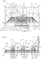
- a view of a preferred embodiment of the invention is shown in perspective from the front.
- the trough 20 comprises, besides the above mentioned beam construction 30 with three transverse beams 31, 32, 33, also three pairs of transverse, substantially parallel, progressive feed screws 61'/ 61", 62'/ 62", 63'/ 63". Said three pairs of progressive feed screws are symmetrically arranged in the screw trough on each side of the belt conveyor 28 adjacent to the bottom portions 24', 24". In the preferred embodiment the three pairs of progressive feed screws have a gradually increasing length l 1 , l 2 , l 3 .
- the respective feed screw is placed so that its discharge end ends adjacent to the edge of or on top of the conveyor belt 25 in a region behind a transverse beam.
- the respective feed screw is journally mounted in the side wall 22', 22", where it also is connected to a driving device 60', 60".
- the first pair of transverse, progressive feed screws 61'/61" is placed essentially in alignment with a symmetry line which is common for said feed screws 61' and 61". Further, they are placed in front of the first transverse beam 31, seen in the transport direction of the conveyor belt, so that the respective discharge end ends in a region in front of the first transverse beam 31.
- the respective feed screw in the first pair of feed screws 61'/61" has a length l 1 , which substantially corresponds to the width of the respective bottom portion 24', 24", and its discharge end ends in close connection to the longitudinal side of the conveyor belt 25, just outside the edge of the respective bottom portion 24', 24".
- a second pair of transverse, progressive feed screws 62'/62" are placed substantially parallel with the first pair of feed screws 61'/61" and essentially aligned with a symmetry line which is common for said second pair of feed screws 62'/62". They are placed in front of the second transverse beam 32, seen in the transport direction of the conveyor belt, so that the respective discharge end ends in a region in front of the second transverse beam 32 and behind the first transverse beam 31.
- the respective feed screw in the second pair of feed screws 62'/62" has a length l 2 , which in this case is somewhat longer than the length of the first pair of feed screws.
- the second pair of feed screws will extend a distance in over the conveyor belt, typically to between about a third to a half of the width of the conveyor belt.
- a third pair of transverse, progressive feed screws 63'/63" is in a similar way placed in front of said transverse third beam 33, which pair has a screw length l 3 , which in this case is somewhat longer than the length of both the first and second pairs of feed screws.
- the third pair of feed screws will extend an additional distance in over the conveyor belt, typically to between about a half to three fourths of the width of the conveyor belt.
- coarse fractions which at the dumping fall along the side walls of the discharge trough, will be continuously fed to the conveyor belt during the paving operation.
- the coarse fractions fed by the feed screws will also to a certain extent be distributed over the width of the conveyor belt by the respective following transverse beam. In this way, a considerably improved homogeneity of the discharged bulk material during the entire paving operation is obtained.
- the output of bulk material from different portions of the sides of the feed trough may be varied.
- the device according to the invention according to the preferred embodiment makes a very flexible operation possible, where the homogeneity of the discharged bulk material may be optimised from the current fractionatings in the discharge trough.
- an additional advantage is achieved, which is connected to the shift of lorries, where the possibility to vary the output from different regions of the trough enables a quicker emptying of the lorry platform so that more time for shift of lorries may be obtained.
- the emptying of the lorry is facilitated, which implies that it will be easier to make the bulk material to suffice during the entire time of the shift of lorry.
- a buffer of bulk material is created along the side walls, i.e. in the region on top of the feed screws.
- the discharge from the sides may for example be increased so that an essentially homogeneous fractionating is achieved.
- the problem of spotwise coarse fractions is solved, which fractions appear in connection with the shift of lorries at conventional paving operations of longer paving distances.
- a preferred embodiment of the invention is shown in a longitudinal section along the symmetry line VIII-VIII in Fig. 7 .
- the feed screws 61', 62' and 63' are placed in a semi-cylindrical discharge channel 70 each arranged in the bottom portion 24'.
- the bottom portion In front of the respective feed screw the bottom portion has a surface 24a', 24b', and 24c', respecitvely, which inclines towards the feed screw.
- the bottom portion 24 rises behind the feed screw as a substantially vertical wall 71. Otherwise, the belt conveyor 60, 25, 26, the transverse beams 31, 32, 33 and the rear wall 21 of the trough are indicated.
- the progressive properties of the feed screws 61'-63" are simplest achieved by permitting the core diameter to have a gradually decreasing diameter in the feeding direction at the same time as its outer thread diameter G 1 , G 2 , G 3 , and thread pitch are kept constant.
- the starting end of the feed screw, at said side walls 22' and 22" has a larger core diameter D 1 , D 2 , D 3 , and a smaller core diameter d 1 , d 2 , d 3 in the final end of the feed screw.
- the feed screws 61' to 63" which in their feeding direction successively reduces their core diameters and correspondingly increases their thread heights, give a contribution of bulk material essentially along the entire length of the feed screw.
- the invention also comprises a beam and a frame comprising at least one beam which are intended to be used in a conventional trough for discharge of bulk material.
- the beam may be afforded a varied shape, as has been described above. It is transversely placed in a suitable manner above the belt conveyor, so that some of the bulk material, which by the belt conveyor is carried in the direction against the outlet, is slowed down. It is also conceivable to arrange the beam in a frame which is placed on top of the belt conveyor. Especially, if several transverse beams are desired, a frame comprising several beams may be used.
- the frame comprises two opposite side plates/beams, in which at least one transverse beam is arranged in a suitable manner.
- the frame may easiest be arranged above the belt conveyor by placing it on top of the belt conveyor, so that the side plates/beams will rest against the protection plates which normally cover the driving chains of the belt conveyor. It is also conceivable to arrange the transverse beams at a desired distance from each other and at desired heights along a centrally arranged beam. This centrally arranged beam may for instance be designed such that it is placed on top of the beam constituting protection for the centrally placed driving chains of the belt conveyor. In this way, the beam constructions may be kept in place, especially if one or more of the transverse beams are designed so that they abut the bottom portions of the trough.
- the frame with this embodiment should not need to be fixed in the trough as it will be kept in place, partly by the weight which the bulk material exerts, partly by the force which is developed when the belt conveyor forces the masses against the outlet.
- the frame will then be pressed downwards towards the basis and backwards towards the rear wall of the trough.
- the frame comprises also a transverse beam in the front edge of the frame, which beam may advantageously be designed such that it constitutes the first transverse beam above the conveyor belt.
- the frame is suitably designed in such a way that the discharge conditions characteristic for the invention may be obtained.
- the first transverse beam should be arranged further from the outlet arranged on the platform than the second beam and preferably it should be arranged in the front half of the trough.
- the front beam is also arranged at a lower height above the conveyor belt than the following one/s.
- a model of a trough 50 was manufactured.
- the model comprises a front wall 50' with an inlet for the belt conveyor 28 in the lower portion with a width covering the entire bottom of the trough, a rear wall 50" with an outlet for the belt conveyor and two side walls in a transparent material, which are not illustrated in the Figs. 9a to 9c .
- the height of the outlet in the rear wall was made larger than the height of the inlet in the front wall.
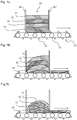
- Figs. 9a to 9c a sequence of an output of bulk material in a conventional trough is schematically shown.
- the bulk material used in the experiment constituted of sand which had been stained to elucidate the flow progress during the discharge.
- the stained sand was filled into the trough in essentially uniform horizontal layers 51 to 54, where the layers are illustrated with different patterns.
- Fig. 9a the trough is shown before the discharge has started and it is illustrated how substantially uniform layers had been arranged in the model, from the uppermost layer 51 to the lowermost layer 54.
- the belt conveyor 28 with the conveyor belt 25 and a number of carriers 26 moved in the direction from the front wall 50' to the rear wall 50", whereby an empty compartment, i.e. the region which is the result of the distance between two carriers 26, will enter the trough through the inlet in the front wall 50'.
- Fig. 9b shows how the layer structure looks when the discharge has been in progress for a while.
- the major part of the discharged bulk material is filled in this empty compartment, substantially by bulk material falling down along the wall 50', which is shown in Fig. 9b .
- a certain filling was observed in the section leaving the trough 50 and thus also a certain fall took place along the inside of the wall 50".
- Fig. 9c shows how the layer structure looks when the discharge has been in progress for another while. From the experiment it could be established that concurrently with bulk material being transported away from the front portions of the trough, substantially adjacent to the front wall, i.e. in direct connection to the inlet for the belt conveyor, a fall occurs from the surface of the rear portions of the hillock, while bulk material in the middle of the hillock has essentially kept its layer structure. To an essentially smaller extent an output of bulk material occurs in direct connection to the outlet in the rear wall 50" with corresponding smaller fall as a consequence, which can be seen in the figure.
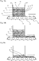
- Fig. 10b shows how the layer structure looks when the discharge has been in progress for a while.
- a discharge progress is obtained with quite another characteristic than previously.
- a considerably more uniform discharge of bulk material from the lowermost layer is obtained, which is understood by the fact the upper surface of the hillock is maintained comparatively horizontal and that the different layers sink comparatively uniformly during the discharge. This indicates that in each section of the hillock, i.e. in each region behind and/or between the respective beam 31, 32, 33, a little sub-volume of bulk material is taken out.
- Fig. 10c it is shown how the layer construction looks when the discharge is almost finished.
- the layer construction is maintained during the entire discharge, which implies that a uniform output of bulk material from the lower layers of the hillock takes place during the entire discharge.
- the bulk material discharged from the trough will contain a contribution from all sections in the trough.
- the discharged bulk material will contain a certain amount of coarse-fractioned bulk material from the front and rear sections of the hillock and a certain amount of finer fractions from the more central sections of the hillock.
- discharge of a more homogenous bulk material may be offered.
- the device according to the invention was tested at paving of asphalt on roads and was compared with paving with a reference machine of a conventional type.
- the device of the invention comprised a conventional trough with a belt conveyor, which had been provided with transverse beams and feed screws according to the most preferred embodiment of the invention as per Fig. 7 .
- the conventional trough was of the kind shown in Fig. 1 , i.e. it comprised a belt conveyor but none of the beams and co-lateral feed screws according to the invention.
- a diagram shows the average density of the asphalt along a paving distance for the reference machine and for the device according to the invention.
- the bars of the diagram describe the average values from a number of measurements made at measurements points along the paving distance.
- the measurement points are at the right border, right wheel track, centre, left wheel track and link border of the road.
- the density i.e. the average value of the homogeneity of the asphalt has increased from 2,272 kg/m 3 for the reference machine to 2,317 kg/m 3 for the device according to the invention.
- the difference in average density between the measurement points has decreased, which also indicates an improved homogeneity, which is shown in the table below.
- a comparison of the size of the so called risk surface occurring at the shifts of lorries was also made.
- the risk surface was measured by means of a thermo-camera, which gives a measure of the density and hence the quality of the paved surface could be evaluated.
- the risk surfaces are those surfaces of the paving which are considered to have an impaired quality, which will imply premature wear and need of early repairs.
- An average value of 12 load shifts with the reference device gave a risk surface of 4.8 m 2
- the device according to invention gave an average value for 9 load shifts of 0.6m 2 .
- the number of transverse beams and the number of feed screws may be varied from at least one beam and/or feed screw and upwards, as well as the location of the beams and/or feed screws, i.e. the height above the belt conveyor, attachment angles and relative positions. If the height of the location of the beams above the belt conveyor is varied, it is possible to control the output of bulk material in different sections of the hillock. It is also conceivable that one or several of the objects of the invention may be reached by arranging several beams vertically, to place the beams at essentially the same or gradually decreasing height above the conveyor belt. Further, it may imply an advantage if the beams are not perpendicularly arranged above the conveyor belt but obliquely, possibly alternately inwards and outwards, whereby an advantageous movement of the bulk material in the hillock could be obtained.
- the beams are not arranged quite horizontally and if the beams are given a curved shape so that the height of the respective beam above the belt conveyor varies transversely.
- the cross-section of the transverse beams may be varied. For instance, transverse beams with the shape I, U, L may be used or beams with round or oval cross-sections. For instance, by giving the beams a non-circular cross-section and having them rotatably mounted, the height of the respective beam above the conveyor belt may be adjusted comparatively simply.
- the driving of the feed screws may be varied.
- the feed screws are driven by said driving units consisting of a motor and a transmission, e.g. a worm gear, a belt or chain transmission, where the motor and transmission may be connected directly to the respective feed screw.
- the feed screws are driven by a motor and a transmission, which coupled together drive several feed screws.
- the design of the trough may be varied.
- the trough need not necessarily be provided with side walls, if the bottom portion is instead made wide and long enough, so that the bulk material being dumped onto the bottom portion cannot fall over the edge.
Landscapes
- Engineering & Computer Science (AREA)
- Mechanical Engineering (AREA)
- Transportation (AREA)
- Aviation & Aerospace Engineering (AREA)
- Architecture (AREA)
- Civil Engineering (AREA)
- Structural Engineering (AREA)
- Structure Of Belt Conveyors (AREA)
- Loading Or Unloading Of Vehicles (AREA)
Claims (5)
- Dispositif pour le traitement d'un matériau en vrac, comprenant une plate-forme (24', 24", 28) destinée à supporter un matériau en vrac et au moins un dispositif de déchargement (28) agencé sur la plate-forme pour alimenter un matériau en vrac placé sur la plate-forme en direction d'une sortie (29) agencée sur la plate-forme, le dispositif de déchargement ayant une direction d'alimentation vers la sortie, une première et une seconde poutre (30, 31, 32, 33) qui sont toutes les deux agencées sur la plate-forme au-dessus du dispositif de déchargement (28), lesquelles première et seconde poutres s'étendent transversalement à la direction d'alimentation du dispositif de déchargement et sur au moins une partie de la largeur du dispositif de déchargement, la seconde poutre (32) étant agencée, dans la direction d'alimentation du dispositif de déchargement, plus près de la sortie (29), située sur la plate-forme, que la première poutre (31), la seconde poutre (32) étant agencée à un niveau plus élevé au-dessus du dispositif de déchargement que la première poutre (31), caractérisé en ce que la plate-forme comprend une pluralité de vis d'alimentation (61', 61", 62', 62", 63', 63") agencées sur chaque côté du dispositif de déchargement (28) dans la direction d'alimentation du dispositif de déchargement pour alimenter le matériau en vrac d'une région extérieure au dispositif de déchargement vers le dispositif de déchargement et sur celui-ci dans une direction d'alimentation de la pluralité de vis d'alimentation (61', 61", 62', 62", 63', 63") qui sont au moins en partie orientées transversalement à la direction d'alimentation du dispositif de déchargement, dans lequel les vis d'alimentation (61', 61", 62', 62", 63', 63") s'étendent au-dessus du dispositif de déchargement (28) et les vis d'alimentation qui sont situées plus près de la sortie (29) s'étendent plus loin au-dessus du dispositif de déchargement que les vis d'alimentation plus éloignées de la sortie.
- Dispositif selon la revendication 1, caractérisé en ce que le dispositif comprend plus de deux poutres agencées au-dessus du dispositif de déchargement et en ce que les poutres, dans la direction d'alimentation, sont agencées à un niveau ascendant au-dessus du dispositif de déchargement.
- Dispositif selon la revendication 1, caractérisé en ce que ladite poutre s'étend transversalement sur toute la largeur du dispositif de déchargement.
- Dispositif selon l'une quelconque des revendications 1 à 3, caractérisé en ce que la pluralité de vis d'alimentation (61', 61", 62', 62", 63', 63") présente un volume ouvert entre les filets de la vis d'alimentation, lequel volume augmente en direction du dispositif de déchargement (28).
- Dispositif selon l'une quelconque des revendications 1 à 4, caractérisé en ce que ladite au moins une poutre (30, 31, 32, 33) a une section transversale non circulaire et peut tourner autour de son axe longitudinal.
Priority Applications (2)
| Application Number | Priority Date | Filing Date | Title |
|---|---|---|---|
| EP17181285.2A EP3309008A1 (fr) | 2007-11-09 | 2008-11-07 | Dispositif pour le traitement d'un matériau en vrac |
| PL08846947T PL2207699T3 (pl) | 2007-11-09 | 2008-11-07 | Urządzenie do obróbki materiału objętościowego, sposób obróbki materiału objętościowego, jak również konstrukcja belkowa służąca do wspomnianej obróbki |
Applications Claiming Priority (2)
| Application Number | Priority Date | Filing Date | Title |
|---|---|---|---|
| SE0702487A SE533994C2 (sv) | 2007-11-09 | 2007-11-09 | Beläggningsmaskin för beläggning av vägbanor samt ett förfarande därför |
| PCT/SE2008/051273 WO2009061278A1 (fr) | 2007-11-09 | 2008-11-07 | Dispositif pour le traitement d'un matériau en vrac, procédé ainsi que structure de poutre destinés audit traitement |
Related Child Applications (2)
| Application Number | Title | Priority Date | Filing Date |
|---|---|---|---|
| EP17181285.2A Division-Into EP3309008A1 (fr) | 2007-11-09 | 2008-11-07 | Dispositif pour le traitement d'un matériau en vrac |
| EP17181285.2A Division EP3309008A1 (fr) | 2007-11-09 | 2008-11-07 | Dispositif pour le traitement d'un matériau en vrac |
Publications (3)
| Publication Number | Publication Date |
|---|---|
| EP2207699A1 EP2207699A1 (fr) | 2010-07-21 |
| EP2207699A4 EP2207699A4 (fr) | 2014-09-03 |
| EP2207699B1 true EP2207699B1 (fr) | 2017-08-23 |
Family
ID=40626009
Family Applications (2)
| Application Number | Title | Priority Date | Filing Date |
|---|---|---|---|
| EP08846947.3A Active EP2207699B1 (fr) | 2007-11-09 | 2008-11-07 | Dispositif pour le traitement d'un matériau en vrac, procédé ainsi que structure de poutre destinés au dit traitement |
| EP17181285.2A Withdrawn EP3309008A1 (fr) | 2007-11-09 | 2008-11-07 | Dispositif pour le traitement d'un matériau en vrac |
Family Applications After (1)
| Application Number | Title | Priority Date | Filing Date |
|---|---|---|---|
| EP17181285.2A Withdrawn EP3309008A1 (fr) | 2007-11-09 | 2008-11-07 | Dispositif pour le traitement d'un matériau en vrac |
Country Status (5)
| Country | Link |
|---|---|
| US (3) | US8646593B2 (fr) |
| EP (2) | EP2207699B1 (fr) |
| PL (1) | PL2207699T3 (fr) |
| SE (1) | SE533994C2 (fr) |
| WO (1) | WO2009061278A1 (fr) |
Families Citing this family (16)
| Publication number | Priority date | Publication date | Assignee | Title |
|---|---|---|---|---|
| US8021078B2 (en) * | 2010-01-25 | 2011-09-20 | Volvo Construction Equipment Ab | Conveyor assembly for an asphalt paving machine |
| PL2377994T3 (pl) * | 2010-04-16 | 2016-06-30 | Joseph Voegele Ag | System przenoszenia materiału dla wykańczarki i zasilacza |
| DE102010054698A1 (de) * | 2010-12-16 | 2012-06-21 | L'Air Liquide, Société Anonyme pour l'Etude et l'Exploitation des Procédés Georges Claude | Vorrichtung zur Austragung von Schüttgut |
| PL2711460T3 (pl) * | 2012-09-21 | 2017-02-28 | Joseph Vögele AG | Maszyna budowlana i system przenoszenia materiału |
| EP2769938B1 (fr) | 2013-02-22 | 2016-02-10 | Joseph Vögele AG | Module d'arbre d'entraînement pour un engin |
| PL2769939T3 (pl) * | 2013-02-22 | 2015-09-30 | Joseph Voegele Ag | Przenośnik ślimakowy dla systemu przenoszenia materiału maszyny budowlanej |
| CN103498406B (zh) * | 2013-10-17 | 2015-07-29 | 陕西中大机械集团有限责任公司 | 摊铺机用折叠式螺旋输料机构 |
| US9725025B2 (en) * | 2014-02-27 | 2017-08-08 | Vincent R. Meier | Unloading apparatus for dry bulk material |
| US9909398B2 (en) * | 2014-06-17 | 2018-03-06 | Schlumberger Technology Corporation | Oilfield material mixing and metering system with auger |
| SE542482C2 (en) * | 2017-02-28 | 2020-05-19 | Adelo Ab | An apparatus and method of improving the quality of an asphalt pavement |
| SE543878C2 (en) * | 2018-08-20 | 2021-08-17 | Adelo Ab | An arrangement for supplying asphalt and a method of producing an asphalt pavement |
| US11140829B2 (en) * | 2018-09-11 | 2021-10-12 | Unverferth Manufacturing Co., Inc. | Farm implement with folding auger |
| US11379325B2 (en) | 2019-10-04 | 2022-07-05 | EMC IP Holding Company LLC | Path failure information sharing between host devices connected to a storage system |
| US11155424B2 (en) * | 2019-11-07 | 2021-10-26 | Cnh Industrial America Llc | Pneumatically inflated pillow for grain bin unload |
| US11050825B1 (en) | 2020-01-30 | 2021-06-29 | EMC IP Holding Company LLC | Storage system port usage information sharing between host devices |
| US11142403B1 (en) * | 2020-12-30 | 2021-10-12 | James Flippin | Self-erecting cargo handling power drive unit |
Family Cites Families (24)
| Publication number | Priority date | Publication date | Assignee | Title |
|---|---|---|---|---|
| US2626068A (en) * | 1949-10-13 | 1953-01-20 | Clifford R Bradshaw | Unloading mechanism for farm wagons |
| US2965379A (en) * | 1957-05-08 | 1960-12-20 | Ganley Bruce Frederick | Mobile hoppers for distributing finely divided materials |
| US3469719A (en) * | 1968-03-29 | 1969-09-30 | Atlas Spokane Inc | Noncylindrical particle storage facility |
| US3724692A (en) * | 1969-08-22 | 1973-04-03 | Ark Rock & Gravel Co | Material delivery system |
| US3986622A (en) * | 1975-12-30 | 1976-10-19 | Allis-Chalmers Canada, Limited | Traveling slot feeder |
| DE2628325A1 (de) * | 1976-06-24 | 1978-01-05 | Strabag Bau Ag | Vorrichtung zum beschicken eines fertigers fuer bituminoese belaege |
| US4630988A (en) * | 1984-07-11 | 1986-12-23 | Hydrotile Machinery Company | Bulk material hopper |
| US4881862A (en) * | 1987-09-30 | 1989-11-21 | Jenike & Johanson, Inc. | Screw seal |
| US5316429A (en) * | 1992-03-24 | 1994-05-31 | Heat And Control, Inc. | Bin loading and emptying of crops having a rounded rollable mass |
| US5553969A (en) * | 1995-02-13 | 1996-09-10 | Reed; Jeffrey | Paving apparatus |
| SE504504C2 (sv) | 1995-06-16 | 1997-02-24 | Conny Andersson | Förfarande och anordning för homogenisering av massgods |
| US5722790A (en) | 1995-12-28 | 1998-03-03 | Venture Corporation | Asphalt paving machine having weir assembly for minimizing segregation of hot mix asphalt |
| US5701726A (en) * | 1997-01-24 | 1997-12-30 | Brenton Engineering Co. | Packaging apparatus for non-round containers |
| US6805516B2 (en) * | 2001-06-04 | 2004-10-19 | E.D. Etnyre & Co. | Roadway paving system and method including roadway paving vehicle and supply truck |
| US7540700B2 (en) * | 2004-06-17 | 2009-06-02 | Deere & Company | Grain cart with intermodal container loader |
| US7543765B1 (en) * | 2005-05-27 | 2009-06-09 | Brad Elling | Self unloading pull-type trailer |
| US7802956B2 (en) * | 2007-05-22 | 2010-09-28 | Schertz Scott F | Apparatus for automatically unloading agricultural material from a storage bag |
| AU2009100247C4 (en) * | 2009-03-18 | 2016-07-28 | Jds (Qld) Pty Ltd | Bin mounted belt conveyor for filling a grain bin |
| US7988403B2 (en) * | 2009-05-18 | 2011-08-02 | Cnh America Llc | Bulk materials cart having dual unload capability |
| CA2680926C (fr) * | 2009-09-29 | 2013-05-14 | Hubertus Dekoning | Tarieres a extracteur pour sacs a grains |
| PL2377994T3 (pl) * | 2010-04-16 | 2016-06-30 | Joseph Voegele Ag | System przenoszenia materiału dla wykańczarki i zasilacza |
| US8556066B2 (en) * | 2011-04-11 | 2013-10-15 | Rethceif Enterprises, Inc. | Bulk material leveling and volumetric measuring and feeding apparatus |
| US10214362B2 (en) * | 2011-04-19 | 2019-02-26 | Cnh Industrial America Llc | Grain unloading system |
| US8939329B2 (en) * | 2011-06-03 | 2015-01-27 | Rdp Technologies, Inc. | Sewage silo with centripetal action discharge arm |
-
2007
- 2007-11-09 SE SE0702487A patent/SE533994C2/sv unknown
-
2008
- 2008-11-07 US US12/741,898 patent/US8646593B2/en active Active
- 2008-11-07 PL PL08846947T patent/PL2207699T3/pl unknown
- 2008-11-07 EP EP08846947.3A patent/EP2207699B1/fr active Active
- 2008-11-07 WO PCT/SE2008/051273 patent/WO2009061278A1/fr not_active Ceased
- 2008-11-07 EP EP17181285.2A patent/EP3309008A1/fr not_active Withdrawn
-
2013
- 2013-10-10 US US14/051,030 patent/US8919537B2/en active Active
- 2013-10-10 US US14/050,912 patent/US8910773B2/en active Active
Non-Patent Citations (1)
| Title |
|---|
| None * |
Also Published As
| Publication number | Publication date |
|---|---|
| EP2207699A1 (fr) | 2010-07-21 |
| US20100263991A1 (en) | 2010-10-21 |
| PL2207699T3 (pl) | 2018-01-31 |
| US20140034453A1 (en) | 2014-02-06 |
| WO2009061278A1 (fr) | 2009-05-14 |
| SE0702487L (sv) | 2009-05-10 |
| US8910773B2 (en) | 2014-12-16 |
| SE533994C2 (sv) | 2011-03-22 |
| US8646593B2 (en) | 2014-02-11 |
| US8919537B2 (en) | 2014-12-30 |
| US20140037407A1 (en) | 2014-02-06 |
| EP2207699A4 (fr) | 2014-09-03 |
| EP3309008A1 (fr) | 2018-04-18 |
Similar Documents
| Publication | Publication Date | Title |
|---|---|---|
| EP2207699B1 (fr) | Dispositif pour le traitement d'un matériau en vrac, procédé ainsi que structure de poutre destinés au dit traitement | |
| DE68923607T2 (de) | Verfahren und Vorrichtung zum Herstellen von bituminösen Strassendecken. | |
| JP2525041B2 (ja) | アスファルト材料の敷設方法および装置 | |
| EP0779395B1 (fr) | Dispositif pour la pose de couches de revêtement | |
| US6375386B1 (en) | Method of remixing hot mix asphalt material in an asphalt paver and a mat of asphalt material having uniform aggregate distribution made by the same | |
| US5533829A (en) | Paving machine with mixing device and discharge conveyor assembly for remixing segregated paving materials | |
| US5035534A (en) | Apparatus for transferring an asphalt-aggregate mixture | |
| CA2903563C (fr) | Appareil de criblage mobile | |
| RU2167703C2 (ru) | Способ и устройство для гомогенизации сыпучего материала | |
| US5553968A (en) | Method and apparatus for conveying and desegregating aggregate | |
| CH639162A5 (de) | Selbstfahrbare gleisbett-reinigungsmaschine. | |
| AU2012279460B2 (en) | Hopper insert for asphalt paving machine | |
| EP3589788B1 (fr) | Procédé de fabrication d'un revêtement d'asphalte et dispositif de ravitaillement destiné à fournir un revêtement d'asphalte | |
| DD143167A5 (de) | Selbstfahrbare gleisbett-reinigungsmaschine mit speichervorrichtung | |
| EP3699359A1 (fr) | Finisseur d'asphalte pour goudronner une surface à goudronner | |
| US5584641A (en) | Stone metering system for railroad track maintenance vehicle | |
| DE102018002945B4 (de) | Behälter mit Stetigförderer zum schichtweisen Austrag von Schüttgut | |
| EP1213390B1 (fr) | Dispositif d'alimentation | |
| AU2021107633A4 (en) | Aggregate Distributor | |
| JPS5929723B2 (ja) | 分岐軌道においても作動が可能な、道床砕石を取出し分離清掃し再充填する砕石清浄化機構 | |
| US3754711A (en) | Low profile feeding spreader | |
| US20020154949A1 (en) | Apparatus and method for re-mixing segregated material | |
| FR2642056A1 (fr) | Dispositif d'alimentation d'une pluralite de tremies de stockage en produits granulaires | |
| FI89396C (fi) | Behaollare foer transport av massgods | |
| NL1029871C2 (nl) | Wagen voor het aanbrengen van vulgoed voor het egaliseren van onregelmatig wegdek. |
Legal Events
| Date | Code | Title | Description |
|---|---|---|---|
| PUAI | Public reference made under article 153(3) epc to a published international application that has entered the european phase |
Free format text: ORIGINAL CODE: 0009012 |
|
| 17P | Request for examination filed |
Effective date: 20100507 |
|
| AK | Designated contracting states |
Kind code of ref document: A1 Designated state(s): AT BE BG CH CY CZ DE DK EE ES FI FR GB GR HR HU IE IS IT LI LT LU LV MC MT NL NO PL PT RO SE SI SK TR |
|
| AX | Request for extension of the european patent |
Extension state: AL BA MK RS |
|
| DAX | Request for extension of the european patent (deleted) | ||
| RAP1 | Party data changed (applicant data changed or rights of an application transferred) |
Owner name: JOSEPH VOEGELE AG |
|
| A4 | Supplementary search report drawn up and despatched |
Effective date: 20140804 |
|
| RIC1 | Information provided on ipc code assigned before grant |
Ipc: B65G 65/46 20060101ALI20140729BHEP Ipc: B65G 67/24 20060101ALI20140729BHEP Ipc: B65G 47/19 20060101ALI20140729BHEP Ipc: E01C 19/48 20060101ALI20140729BHEP Ipc: B60P 1/38 20060101AFI20140729BHEP |
|
| 17Q | First examination report despatched |
Effective date: 20160915 |
|
| REG | Reference to a national code |
Ref country code: DE Ref legal event code: R079 Ref document number: 602008051804 Country of ref document: DE Free format text: PREVIOUS MAIN CLASS: B60P0001380000 Ipc: B65G0065400000 |
|
| GRAP | Despatch of communication of intention to grant a patent |
Free format text: ORIGINAL CODE: EPIDOSNIGR1 |
|
| RIC1 | Information provided on ipc code assigned before grant |
Ipc: B65G 65/46 20060101ALI20170213BHEP Ipc: B60P 1/38 20060101ALI20170213BHEP Ipc: B65G 67/24 20060101ALI20170213BHEP Ipc: B65G 65/40 20060101AFI20170213BHEP Ipc: E01C 19/48 20060101ALI20170213BHEP Ipc: B65G 47/19 20060101ALI20170213BHEP |
|
| INTG | Intention to grant announced |
Effective date: 20170303 |
|
| GRAS | Grant fee paid |
Free format text: ORIGINAL CODE: EPIDOSNIGR3 |
|
| GRAA | (expected) grant |
Free format text: ORIGINAL CODE: 0009210 |
|
| AK | Designated contracting states |
Kind code of ref document: B1 Designated state(s): AT BE BG CH CY CZ DE DK EE ES FI FR GB GR HR HU IE IS IT LI LT LU LV MC MT NL NO PL PT RO SE SI SK TR |
|
| REG | Reference to a national code |
Ref country code: GB Ref legal event code: FG4D |
|
| RIN1 | Information on inventor provided before grant (corrected) |
Inventor name: CARLSSON, ALLAN Inventor name: ANDERSSON, CONNY |
|
| REG | Reference to a national code |
Ref country code: CH Ref legal event code: EP |
|
| REG | Reference to a national code |
Ref country code: AT Ref legal event code: REF Ref document number: 921088 Country of ref document: AT Kind code of ref document: T Effective date: 20170915 |
|
| REG | Reference to a national code |
Ref country code: IE Ref legal event code: FG4D |
|
| REG | Reference to a national code |
Ref country code: DE Ref legal event code: R096 Ref document number: 602008051804 Country of ref document: DE |
|
| REG | Reference to a national code |
Ref country code: FR Ref legal event code: PLFP Year of fee payment: 10 |
|
| REG | Reference to a national code |
Ref country code: NL Ref legal event code: MP Effective date: 20170823 |
|
| REG | Reference to a national code |
Ref country code: LT Ref legal event code: MG4D |
|
| REG | Reference to a national code |
Ref country code: AT Ref legal event code: MK05 Ref document number: 921088 Country of ref document: AT Kind code of ref document: T Effective date: 20170823 |
|
| PG25 | Lapsed in a contracting state [announced via postgrant information from national office to epo] |
Ref country code: AT Free format text: LAPSE BECAUSE OF FAILURE TO SUBMIT A TRANSLATION OF THE DESCRIPTION OR TO PAY THE FEE WITHIN THE PRESCRIBED TIME-LIMIT Effective date: 20170823 Ref country code: NL Free format text: LAPSE BECAUSE OF FAILURE TO SUBMIT A TRANSLATION OF THE DESCRIPTION OR TO PAY THE FEE WITHIN THE PRESCRIBED TIME-LIMIT Effective date: 20170823 Ref country code: NO Free format text: LAPSE BECAUSE OF FAILURE TO SUBMIT A TRANSLATION OF THE DESCRIPTION OR TO PAY THE FEE WITHIN THE PRESCRIBED TIME-LIMIT Effective date: 20171123 Ref country code: LT Free format text: LAPSE BECAUSE OF FAILURE TO SUBMIT A TRANSLATION OF THE DESCRIPTION OR TO PAY THE FEE WITHIN THE PRESCRIBED TIME-LIMIT Effective date: 20170823 Ref country code: SE Free format text: LAPSE BECAUSE OF FAILURE TO SUBMIT A TRANSLATION OF THE DESCRIPTION OR TO PAY THE FEE WITHIN THE PRESCRIBED TIME-LIMIT Effective date: 20170823 Ref country code: HR Free format text: LAPSE BECAUSE OF FAILURE TO SUBMIT A TRANSLATION OF THE DESCRIPTION OR TO PAY THE FEE WITHIN THE PRESCRIBED TIME-LIMIT Effective date: 20170823 Ref country code: FI Free format text: LAPSE BECAUSE OF FAILURE TO SUBMIT A TRANSLATION OF THE DESCRIPTION OR TO PAY THE FEE WITHIN THE PRESCRIBED TIME-LIMIT Effective date: 20170823 |
|
| PG25 | Lapsed in a contracting state [announced via postgrant information from national office to epo] |
Ref country code: LV Free format text: LAPSE BECAUSE OF FAILURE TO SUBMIT A TRANSLATION OF THE DESCRIPTION OR TO PAY THE FEE WITHIN THE PRESCRIBED TIME-LIMIT Effective date: 20170823 Ref country code: BG Free format text: LAPSE BECAUSE OF FAILURE TO SUBMIT A TRANSLATION OF THE DESCRIPTION OR TO PAY THE FEE WITHIN THE PRESCRIBED TIME-LIMIT Effective date: 20171123 Ref country code: IS Free format text: LAPSE BECAUSE OF FAILURE TO SUBMIT A TRANSLATION OF THE DESCRIPTION OR TO PAY THE FEE WITHIN THE PRESCRIBED TIME-LIMIT Effective date: 20171223 Ref country code: GR Free format text: LAPSE BECAUSE OF FAILURE TO SUBMIT A TRANSLATION OF THE DESCRIPTION OR TO PAY THE FEE WITHIN THE PRESCRIBED TIME-LIMIT Effective date: 20171124 Ref country code: ES Free format text: LAPSE BECAUSE OF FAILURE TO SUBMIT A TRANSLATION OF THE DESCRIPTION OR TO PAY THE FEE WITHIN THE PRESCRIBED TIME-LIMIT Effective date: 20170823 |
|
| PG25 | Lapsed in a contracting state [announced via postgrant information from national office to epo] |
Ref country code: CZ Free format text: LAPSE BECAUSE OF FAILURE TO SUBMIT A TRANSLATION OF THE DESCRIPTION OR TO PAY THE FEE WITHIN THE PRESCRIBED TIME-LIMIT Effective date: 20170823 Ref country code: DK Free format text: LAPSE BECAUSE OF FAILURE TO SUBMIT A TRANSLATION OF THE DESCRIPTION OR TO PAY THE FEE WITHIN THE PRESCRIBED TIME-LIMIT Effective date: 20170823 Ref country code: RO Free format text: LAPSE BECAUSE OF FAILURE TO SUBMIT A TRANSLATION OF THE DESCRIPTION OR TO PAY THE FEE WITHIN THE PRESCRIBED TIME-LIMIT Effective date: 20170823 |
|
| REG | Reference to a national code |
Ref country code: DE Ref legal event code: R097 Ref document number: 602008051804 Country of ref document: DE |
|
| PG25 | Lapsed in a contracting state [announced via postgrant information from national office to epo] |
Ref country code: EE Free format text: LAPSE BECAUSE OF FAILURE TO SUBMIT A TRANSLATION OF THE DESCRIPTION OR TO PAY THE FEE WITHIN THE PRESCRIBED TIME-LIMIT Effective date: 20170823 Ref country code: SK Free format text: LAPSE BECAUSE OF FAILURE TO SUBMIT A TRANSLATION OF THE DESCRIPTION OR TO PAY THE FEE WITHIN THE PRESCRIBED TIME-LIMIT Effective date: 20170823 |
|
| PG25 | Lapsed in a contracting state [announced via postgrant information from national office to epo] |
Ref country code: MC Free format text: LAPSE BECAUSE OF FAILURE TO SUBMIT A TRANSLATION OF THE DESCRIPTION OR TO PAY THE FEE WITHIN THE PRESCRIBED TIME-LIMIT Effective date: 20170823 |
|
| PLBE | No opposition filed within time limit |
Free format text: ORIGINAL CODE: 0009261 |
|
| STAA | Information on the status of an ep patent application or granted ep patent |
Free format text: STATUS: NO OPPOSITION FILED WITHIN TIME LIMIT |
|
| PG25 | Lapsed in a contracting state [announced via postgrant information from national office to epo] |
Ref country code: CH Free format text: LAPSE BECAUSE OF NON-PAYMENT OF DUE FEES Effective date: 20171130 Ref country code: LI Free format text: LAPSE BECAUSE OF NON-PAYMENT OF DUE FEES Effective date: 20171130 |
|
| 26N | No opposition filed |
Effective date: 20180524 |
|
| PG25 | Lapsed in a contracting state [announced via postgrant information from national office to epo] |
Ref country code: SI Free format text: LAPSE BECAUSE OF FAILURE TO SUBMIT A TRANSLATION OF THE DESCRIPTION OR TO PAY THE FEE WITHIN THE PRESCRIBED TIME-LIMIT Effective date: 20170823 Ref country code: LU Free format text: LAPSE BECAUSE OF NON-PAYMENT OF DUE FEES Effective date: 20171107 |
|
| REG | Reference to a national code |
Ref country code: BE Ref legal event code: MM Effective date: 20171130 |
|
| REG | Reference to a national code |
Ref country code: IE Ref legal event code: MM4A |
|
| PG25 | Lapsed in a contracting state [announced via postgrant information from national office to epo] |
Ref country code: MT Free format text: LAPSE BECAUSE OF NON-PAYMENT OF DUE FEES Effective date: 20171107 |
|
| PG25 | Lapsed in a contracting state [announced via postgrant information from national office to epo] |
Ref country code: IE Free format text: LAPSE BECAUSE OF NON-PAYMENT OF DUE FEES Effective date: 20171107 |
|
| PG25 | Lapsed in a contracting state [announced via postgrant information from national office to epo] |
Ref country code: BE Free format text: LAPSE BECAUSE OF NON-PAYMENT OF DUE FEES Effective date: 20171130 |
|
| PG25 | Lapsed in a contracting state [announced via postgrant information from national office to epo] |
Ref country code: HU Free format text: LAPSE BECAUSE OF FAILURE TO SUBMIT A TRANSLATION OF THE DESCRIPTION OR TO PAY THE FEE WITHIN THE PRESCRIBED TIME-LIMIT; INVALID AB INITIO Effective date: 20081107 |
|
| PG25 | Lapsed in a contracting state [announced via postgrant information from national office to epo] |
Ref country code: CY Free format text: LAPSE BECAUSE OF NON-PAYMENT OF DUE FEES Effective date: 20170823 |
|
| PG25 | Lapsed in a contracting state [announced via postgrant information from national office to epo] |
Ref country code: TR Free format text: LAPSE BECAUSE OF FAILURE TO SUBMIT A TRANSLATION OF THE DESCRIPTION OR TO PAY THE FEE WITHIN THE PRESCRIBED TIME-LIMIT Effective date: 20170823 |
|
| PG25 | Lapsed in a contracting state [announced via postgrant information from national office to epo] |
Ref country code: PT Free format text: LAPSE BECAUSE OF FAILURE TO SUBMIT A TRANSLATION OF THE DESCRIPTION OR TO PAY THE FEE WITHIN THE PRESCRIBED TIME-LIMIT Effective date: 20170823 |
|
| P01 | Opt-out of the competence of the unified patent court (upc) registered |
Effective date: 20230524 |
|
| PGFP | Annual fee paid to national office [announced via postgrant information from national office to epo] |
Ref country code: DE Payment date: 20251128 Year of fee payment: 18 |
|
| PGFP | Annual fee paid to national office [announced via postgrant information from national office to epo] |
Ref country code: GB Payment date: 20251125 Year of fee payment: 18 |
|
| PGFP | Annual fee paid to national office [announced via postgrant information from national office to epo] |
Ref country code: IT Payment date: 20251127 Year of fee payment: 18 |
|
| PGFP | Annual fee paid to national office [announced via postgrant information from national office to epo] |
Ref country code: FR Payment date: 20251128 Year of fee payment: 18 |
|
| PGFP | Annual fee paid to national office [announced via postgrant information from national office to epo] |
Ref country code: PL Payment date: 20251107 Year of fee payment: 18 |