EP2207706B1 - Modulares kinderwagen-sitz- und -liegesystem mit aufnahmevorrichtung - Google Patents
Modulares kinderwagen-sitz- und -liegesystem mit aufnahmevorrichtung Download PDFInfo
- Publication number
- EP2207706B1 EP2207706B1 EP08837444.2A EP08837444A EP2207706B1 EP 2207706 B1 EP2207706 B1 EP 2207706B1 EP 08837444 A EP08837444 A EP 08837444A EP 2207706 B1 EP2207706 B1 EP 2207706B1
- Authority
- EP
- European Patent Office
- Prior art keywords
- receiving device
- plate
- pushchair
- seat
- child
- Prior art date
- Legal status (The legal status is an assumption and is not a legal conclusion. Google has not performed a legal analysis and makes no representation as to the accuracy of the status listed.)
- Not-in-force
Links
- 239000000463 material Substances 0.000 claims description 12
- 230000000295 complement effect Effects 0.000 claims 1
- 230000001419 dependent effect Effects 0.000 claims 1
- 210000002414 leg Anatomy 0.000 description 14
- 239000004753 textile Substances 0.000 description 6
- 239000004744 fabric Substances 0.000 description 5
- 229920003023 plastic Polymers 0.000 description 4
- 230000007246 mechanism Effects 0.000 description 3
- 239000004033 plastic Substances 0.000 description 3
- 230000001681 protective effect Effects 0.000 description 3
- 230000001360 synchronised effect Effects 0.000 description 3
- 210000001217 buttock Anatomy 0.000 description 2
- 230000000694 effects Effects 0.000 description 2
- 238000007373 indentation Methods 0.000 description 2
- 244000043261 Hevea brasiliensis Species 0.000 description 1
- 239000004809 Teflon Substances 0.000 description 1
- 229920006362 Teflon® Polymers 0.000 description 1
- 230000008878 coupling Effects 0.000 description 1
- 238000010168 coupling process Methods 0.000 description 1
- 238000005859 coupling reaction Methods 0.000 description 1
- 238000006073 displacement reaction Methods 0.000 description 1
- 239000013013 elastic material Substances 0.000 description 1
- 230000001856 erectile effect Effects 0.000 description 1
- 239000006260 foam Substances 0.000 description 1
- 210000003127 knee Anatomy 0.000 description 1
- 150000002736 metal compounds Chemical class 0.000 description 1
- 229920003052 natural elastomer Polymers 0.000 description 1
- 229920001194 natural rubber Polymers 0.000 description 1
- 230000000474 nursing effect Effects 0.000 description 1
- 230000000276 sedentary effect Effects 0.000 description 1
- 239000007787 solid Substances 0.000 description 1
Images



Classifications
-
- B—PERFORMING OPERATIONS; TRANSPORTING
- B62—LAND VEHICLES FOR TRAVELLING OTHERWISE THAN ON RAILS
- B62B—HAND-PROPELLED VEHICLES, e.g. HAND CARTS OR PERAMBULATORS; SLEDGES
- B62B7/00—Carriages for children; Perambulators, e.g. dolls' perambulators
- B62B7/04—Carriages for children; Perambulators, e.g. dolls' perambulators having more than one wheel axis; Steering devices therefor
- B62B7/12—Carriages for children; Perambulators, e.g. dolls' perambulators having more than one wheel axis; Steering devices therefor convertible, e.g. into children's furniture or toy
- B62B7/123—Carriages for children; Perambulators, e.g. dolls' perambulators having more than one wheel axis; Steering devices therefor convertible, e.g. into children's furniture or toy from seat to bed
-
- B—PERFORMING OPERATIONS; TRANSPORTING
- B62—LAND VEHICLES FOR TRAVELLING OTHERWISE THAN ON RAILS
- B62B—HAND-PROPELLED VEHICLES, e.g. HAND CARTS OR PERAMBULATORS; SLEDGES
- B62B7/00—Carriages for children; Perambulators, e.g. dolls' perambulators
- B62B7/04—Carriages for children; Perambulators, e.g. dolls' perambulators having more than one wheel axis; Steering devices therefor
- B62B7/14—Carriages for children; Perambulators, e.g. dolls' perambulators having more than one wheel axis; Steering devices therefor with detachable or rotatably-mounted body
- B62B7/142—Means for securing the body to the frame
-
- B—PERFORMING OPERATIONS; TRANSPORTING
- B62—LAND VEHICLES FOR TRAVELLING OTHERWISE THAN ON RAILS
- B62B—HAND-PROPELLED VEHICLES, e.g. HAND CARTS OR PERAMBULATORS; SLEDGES
- B62B9/00—Accessories or details specially adapted for children's carriages or perambulators
- B62B9/10—Perambulator bodies; Equipment therefor
- B62B9/102—Perambulator bodies; Equipment therefor characterized by details of the seat
- B62B9/104—Perambulator bodies; Equipment therefor characterized by details of the seat with adjustable or reclining backrests
Definitions
- the invention relates to a modular stroller seat and -Liegesystem and in particular a receiving device as a component thereof.
- Strollers are known in many embodiments or designs. They can be designed as folding models, sports or comfort models, have seats, reclining seats or inserts that are only suitable as a lounger or carrying lie. Combinations of seats that can be converted into couches are also known. Furthermore, also seats or recliners, especially for children of different ages on a stroller chassis can be replaced.
- a couch insert itself can also be multifarious, where it is usually designed so that the child can be taken asleep from the carriage frame and worn, so as a carrying bag. An attachment intended for the child who can already sit is the so-called "sports seat".
- chassis collapsible so that the chassis can be transported or removed with space saving taking off seat and / or reclining, it is particularly focused on the dimensions of a trunk in cars.
- a receiving device which is to be arranged detachably on a stroller and is provided as a support for a child seat or a couch.
- the receiving device has on opposite sides of a first plate gripping elements or other elements on which profiles are pivotally mounted about a pivot point and can be fixed via a locking device for releasable positioning.
- the first plate represents a seat surface element, the second plate a back element and the third plate an element that can serve as a leg rest.
- Via a connecting element the plates are coupled together, wherein one end of the connecting element is coupled to the second plate and the other end to the third plate.
- Strollers are known whose side parts of the chassis designed scissor-like are, like that in the EP 1 279 583 revealed. These scissors-type racks are locked during use so that the scissors are fixed and are unlocked for folding.
- a transverse strut which connects the two facing the seat ends of a pair of scissors, has latching means which can be brought into engagement with corresponding, arranged on the seat or the carrying bag locking means, so that a secure arrangement of the seat, or the carrying bag, on Frame is given.
- the positioning of the seat or the carrying bag over the locking means of the cross member of the frame is complex, since when holding the seat usually no more visibility is given to all Raststoffchue.
- a collapsible stroller reveals the DE 20 2004 019 178 U1 , which describes a stroller with folding frame so that the volume of the folded chassis compared to the known embodiments is still reduced.
- a convertible seat reclining insert for stroller according to the preamble of claim 1 is known from DE 20 2005 019 191 U1 known.
- the adjustability is achieved via adapters, adjustable holders and hangers.
- the seat and recliner for a stroller takes the DE 20 2004 019 108 U1 document describing a seat and recliner insert for a stroller consisting of a seat and backrest consisting of a padding and a cover, and two lateral parts forming the lateral boundaries.
- the seat and recliner is designed to facilitate handling and to adapt the seat and back of the seat and recliner to different seasons. This object is achieved by the seat and back area of the seat and recliner insert is connected by connecting elements releasably connected to the side parts of the frame of the stroller.
- the DE 202 10 430 U1 describes a stroller with a chassis and with a present in a fabric cover sitting and lying insert, the armrests are associated with the fabric cover has an erectile back, so that the edge of the back is erectable and thus the child during the lowering of the back against Falling out is protected. Due to the folding mechanism and the edge position, the backrest has a limited length.
- the object of the invention to provide an improved stroller seat and -Liegevoriques.
- This object is achieved by a receiving device with the features of claim 1 and by a modular stroller seat and -Liegesystem with the features of claim 11.
- Preferred embodiments are described by the subclaims.
- a first embodiment relates to the receiving device, which can be arranged on a stroller frame such that a child seat pad or alternatively a deck pad can be accommodated therein.
- the receiving device comprises a plate on which two elements are arranged laterally, which can serve as handles, but also as part of an adjustment for adjusting the receiving device from a sedentary to a reclining position.
- the handles are advantageously cleverly arranged laterally, so that they are easily accessible to the operator.
- Further plates are arranged on the gripped plate so that the plates form a double-link chain which advantageously provides a flexible base of the receiving device.
- a connecting element Via a connecting element, all plates are in operative connection, since a four-bar joint, which is provided by the handle element and two profiles arranged on the handle elements and two different locations of the connecting element with a degree of freedom such that advantageously rotating one of the profiles about its on the handle element present fulcrum synchronous adjustment of the plates, which are articulated to the plate with the handles result. Further, one of the hinged to the handle profiles is equipped with a locking device, so that the set by the four-joint configuration of the two-link chain can be determined.
- a further embodiment relates to the fact that the four-bar linkage is operatively connected to the double-link chain of plates in such a way that it can be advantageously set in a variety of configurations, so that a seating arrangement with an upright seating position up to a lying arrangement can result.
- the locking device can be configured as a knob or push button, knob or push button are accordingly easy to handle and easily accessible each left and / or right of the seat or lying surfaces of the stroller arranged outside of the handle elements.
- the plates forming the double-link chain may have mutually independent geometries, so that approximately the plate providing the seating surface may advantageously be square, whereas a plate providing the back section may be a long, narrow rectangle can have approximate rectangular shape with indentation or another shape.
- one embodiment relates to the connecting member which connects the second panel, which is advantageously a back portion, to the third panel via the seat panel portion providing a leg or footrest.
- the connecting element advantageously absorbs tensile forces, so that the synchronous adjustment of the plates can take place via the actuation of the four-bar linkage.
- An actuation of the designed as a "pulling element" connecting element facilitates with appropriate adjustment of the four-bar linkage also a rapid collapse or folding of the plates to each other, so that the receiving device is easy to fold for transport.
- the connecting element may be a rope or a stranded wire.
- FIG. 1 Another embodiment relates to a modular stroller seat and cradle system comprising the cradle of the present invention together with a child seat and, alternatively, a cot seat.
- the child seat cover, respectively the child bed pad are designed in their geometry such that they are suitable to be inserted into the receiving device.
- a child seat pad while a seat surface plate, which is also pivotally connected to a backrest element, wherein the backrest element has at its end remote from the pivotally connected end an end formed as a Umgriff edge, which can be brought into engagement with the back portion of the receiving device.
- the child seat pad can be easily connected securely by hanging with the receiving device.
- the child seat cushion can be upholstered and that the padding can also be provided with a textile cover.
- yet another embodiment is directed to a baby carrier bag as part of the modular stroller seating and guiding system, wherein the receiving device is adjustable such that the first, second and third plates form a horizontal surface on which an infant carrier bag can be placed, which is advantageous can be secured by the side wings, which are provided on the receiving device.
- both the child seat cushion and a child rest pad can be connected to corresponding fastening devices, which are advantageously provided by push buttons or hook and loop fastener elements and which, with respective corresponding fastening elements provided at corresponding suitable locations, cause the baby carriage seat or the child rest pad in the Recording device is held securely and non-slip. It is particularly advantageous that by a few simple steps, such as the release of the fixing device, such as a push button, and the operation of the fixing device on the four-bar linkage, the positions of the receiving device can be changed quickly, so that the stroller frame of recording device and child seat pad or nursery pad easily can be separated, for example, to convert this or to transport them.
- FIG. 1 shows an exploded view of a child seat pad, the receiving device according to the invention and a stroller frame,
- FIG. 2 shows the recording device according to the invention, provided with a child seat, arranged on the stroller frame in a side view,
- FIG. 3 shows a side view of the seat of the invention received by the child seat in lying position
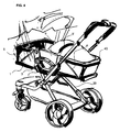
- FIG. 4 shows a perspective view of the receiving device according to the invention, arranged on a stroller frame and provided with a nursing bag and a corresponding protective sky,
- FIG. 5 shows a side view of the receiving device according to the invention, arranged on a buggy stroller frame, in sitting position.
- any suitable stroller frame be it a so-called sports stroller frame or a buggy stroller frame or other suitable stroller frame to understand.
- a “child seat pad” is to be understood below as the pad that is mounted on the cradle for convenience and safety of the child, so that the child is held comfortably in a sitting or lying position.
- the upholstery of the child seat cushion can be different thicknesses, they can include a few millimeters to a few centimeters, from a padding only in the seat and back area to comfortable Soauspolsterungen all embodiments of the child seat cover are possible.
- a "trapezoidal” plate is understood below to mean the mathematical trapezoid, which is a quadrilateral having two parallel sides. Usually, the trapezoidal plate will mean a symmetrical trapezoid, but also squares and rectangles are mathematically trapezoids. An “approximately trapezoidal” may thus be such a plate whose sides may well have indentations or bulges.
- the "plate” can be any flat or approximately flat element that does not have to be completely closed at all.
- this also means a plate with one or more central recesses, ie a plate whose appearance is close to a frame or which is a frame.
- the "plate” can also be flexible in itself.
- an “approximately flat plate” also includes plates that have bulges, elevations or depressions, so for example, an ergonomic shape.
- a "four-bar linkage" hereinafter means a pivotal arrangement of four communicating points which form a joint with one degree of freedom. The rotation about a hinge point causes the displacement of at least two hinge points.
- FIGS. 1 to 5 show the recording device according to the invention 1.
- FIGS. 2 to 5 It can be seen how the receiving device 1 in the mounted state on a stroller frame 20 for a stroller, as in FIGS. 2 to 4 or a buggy stroller frame 50 as in FIG. 5 , can be arranged.
- FIG. 1 illustrates the structure of the modular stroller seat and -Liegesystems, here with a child seat cushion 30 on a stroller frame 20 of the type "stroller" in a raised view.
- FIG. 1 illustrates that the receiving device 1 is suitable to be arranged detachably on a stroller frame 20 to accommodate a child seat pad 30.
- a couch pad in FIG. 4 a baby carrier bag 40, are placed in the receiving device 1.
- the receiving device 1 comprises two gripping elements 7, which are arranged on opposite sides of a first plate, which is here represented by the seat surface portion 9 '.
- a second plate 9, which provides the back portion 9, is pivotally connected to another side of the first plate via the pivot 2, finally, a third plate opposite the second plate as leg and foot rest 9 "also via a hinge 2 articulated with the A connecting element, which in the present case is provided by an edge 4 of a side wing 6, connects the back section 9 to the leg and foot rest 9 ".
- a first profile 8 is rotatably articulated at a pivot point 7 'of the grip element 7, at a distance therefrom
- a second profile 8' is likewise rotatably articulated at a second pivot point 7 "of the grip element 7, the ends facing away from the grip element 7 of the first and second profiles 8, 8 'are coupled to a first point 5 of the connecting element or to a second point 5' of the connecting element such that the first pivot point 7 'engages with the second pivot point 7 "and the two points 5 and 5'
- the first profile 8 is designed so that it emits the edge 4 of the side wing 6 enclosing prehending and rotatably connected by a rivet with the side wing material, which may consist of a textile or plastic.
- the second profile 8 is designed so that it emits the edge 4 of the side wing 6 enclosing prehending and rotatably connected by a rivet with the side wing material, which may consist of a textile or plastic.
- the receiving device 1 has a locking device on, which at the first pivot point 7 ', on which the first profile 8 is pivotally connected to the handle member 7, is arranged.
- a locking device on, which at the first pivot point 7 ', on which the first profile 8 is pivotally connected to the handle member 7, is arranged.
- a locking device can ultimately serve any element which has a latching element which is in engagement with a arranged on the profile 8 corresponding latching element.
- the figures show as a locking device a rotary knob 3, which can be actuated by turning such that the latching elements are brought into different positions and thus the locking device is actuated in discrete latching steps. It is conceivable to provide only one of the two gripping elements 7 on a receiving device with a locking device. Of course, locking devices are possible, which can be operated continuously.
- the provided four-bar mechanism basically serves to provide the plates which provide the spine portion 9, the seat surface portion 9 'and the leg and footrest 9 "by rotating a member, respectively the first profile 8, via the rotary knob 3 in a plurality of positions
- An advantage of the four-bar arrangement is that the actuation is effected only via the rotary knob 3 and thus the change in position of only the first profile 8 over the present one degree of freedom of the four-bar linkage
- the second profile 8 "is moved, and with him train and possibly pressure on the connecting element is exercised.
- the connecting element which in the present case is provided in all figures as an edge 4 of a side wing 6, is made of a material which is suitable for absorbing tensile forces.
- An embodiment of the connecting element that allows the recording of compressive forces may be desirable for reasons of stability.
- Such an element may according to a rope, a strand, or - to accommodate pressure forces - a flat profile, a rod, in particular a flexible rod, or a hose material made of a plastic, a natural rubber, a metal compound, Teflon, herringbone or other materials that have a suitable stiffness at the desired flexibility.
- Such an element can be introduced approximately into a hemstitch of a fabric made of textile or plastic material side wing 6, so that by a corresponding procured edge of the profiles 8,8 'of the edge 4 by clamping in a trained edge of the profiles 8,8' recorded as a clip can be.
- a profile can also be coupled in another way with the edge of the side wing or, if appropriate, with an alternative connecting element, for example when the connecting element is shown decoupled from the side wing. Then the edge of the side wing does not have the function of connecting the plates of the receiving device; this task is then perceived via the connecting element, which may be located a few centimeters apart from the side wing above it.
- the plates which provide the spine portion 9, the seat surface portion 9 'and the leg and footrest 9 " may have different trapezoidal or approximately trapezoidal geometries.
- the shape of the seat surface 9 ' may taper away from the buttocks to the knees, or the back portion 9 may also be tapered from the buttocks to the head, so that both plates would form symmetrical trapezoids.
- the third panel may provide the leg and footrest 9 "per se, but other panels or angles may be disposed on the third panel 9" such that approximately a small edge 10 is provided for adjusting the feet.
- the side wing 6 is presently arranged so that it runs along a large part of the back portion 9, along the seat surface portion 9 'and along a large portion of the leg and footrest 9 ".
- a side wing could also be correspondingly shorter, but it should be ensured that when the side wing provides the connecting element required for raising and lowering the panels in the sitting and lying position, the connecting element is connected to the plates such that the Nevertheless, actuation of the four-bar linkage reliably leads to a change of the plate positions relative to one another, so that the desired sitting or lying position can be adjusted.
- the material of the side wing may be an opaque solid textile material, but it may also be a transparent plastic material or a net material. Decisive for the selection of the material is, inter alia, the safety of the child, which is improved by the guidance provided by the side wings.
- the child should also be held securely in a position in a child seat support according to the invention, which is supported in particular by an elastic material.
- the side wing 6, as in the FIGS. 1 to 5 illustrated, allow a child seat pad 30, 55 inserted into the receiving device 1 laterally limited and thus preserved from slipping and lateral tilting. Not only the child is advantageously guided and held by the provided side wings 6; also the loss of entrained objects, from the pacifier to the teddy bear, is prevented, or the risk of losing is at least reduced.
- FIG. 1 also clarifies that in this case a modular stroller seat and - liegesystem is provided. It may consist of differently procured and padded child seat and / or -Laufeauflagen and includes the recording device according to the invention.
- FIG. 1 shows the recording device 1 according to the invention in combination with a child seat pad 30 which is designed so that it can be easily accommodated in the receiving device 1.
- the child seat cover 30 has a seat surface plate 31 which is pivotally connected to a backrest member 32 via the hinge 36.
- the backrest element 32 has, moreover, at its end which is remote from the pivotally coupled end, an edge formed as a wrap-around 33. This edge is such that it surrounds the back portion 9 of the receiving device 1, thereby allowing the child seat support 30 is not only received in the receiving device 1, but mounted and additionally secured. Another advantage that results from this is that the edge formed by the wrap-around 33 together with the encompassed back section 9 provides a backrest of advantageous length, namely 51 cm. Of course, the entire resulting backrest also shorter or longer, namely z. Up to 55 cm, thereby taking into account the fact that children are now very young at a very young age, as was the case on average at the same age years ago.
- the backrest can be up to the length of 65 cm run without affecting the handling of the stroller would be. This even larger children can be safely and comfortably transported in the stroller and the head of the child can be safely taken on the appropriate support of the child seat.
- the child seat cover 30 is presently equipped with a leg rest element 34, which is also connected to the seat surface plate 31 pivotally connected via a hinge 36.
- the hinges 36 of the child seat cover 30 come to rest virtually on the pivot joints 2 of the receiving device 1 and, since the pivot joints 36 of the child seat cover 30th are not found, but adapt to the pad, the child seat cover 30 according to the adjustment of the receiving device 1 according to the sitting position or a reclining position.
- This is advantageously achieved that the child can be accommodated in a comfortable secure seat with protective side boundary and that by easy and skillful handling, namely by the operation of the knob 3 from the outside, the sitting position can be changed to a lying position without the child shaken or even awakened.
- the child seat cushion 30 may be advantageously provided in the region of the seat surface plate 31 and the backrest member 32 with a cushion.
- This pad has a considerable thickness in this case and is also provided with a protective textile cover.
- the child seat cover 55 which can be seen in Figure 5, however, has only a relatively sparingly thin pad, since the buggy or travel stroller shown purposefully equipped with less comfort.
- the child seat pad 55 may consist of a soft, thin cushion pad. Nevertheless, even here is made possible by the provision of the side wings 6 increased security for the seated or lying child.
- the receiving device 1 has locking elements 60 which are suitable for being brought into engagement with corresponding latching means 65 mounted on a stroller frame 20, 50.
- the recording device 1 can be quickly and easily arranged safely on the frame and just as quickly released from this.
- the embodiment is in Fig. 5 to recognize the shape of the projections 65a of the locking means 65 which are provided on the stroller frame 20. These are four in the direction of travel obliquely upwardly facing elements that form a V-shaped element on both sides of the frame. If the receiving device is placed with its opposite locking means 60 on this locking means, the V-shape leads to an automatic centering of the receiving device 1 on the stroller frame 20, wherein the centering is further facilitated by the mold shape.
- the four projections only two elements can be provided and also on the trough shape can be omitted.
- the receiving device 1 does not have to be removed from the stroller frame 20, 50 when the child seat support 30 is against a lying support to be replaced.
- a couch pad is carried about by a baby carrier bag 40 as shown in FIG FIG. 4 , represented.
- the plates which define the back section 9, the seat surface section 9 'and the leg and foot rest 9 "are caused to rotate in one direction only by turning the rotary knob 3 on the four-bar linkage
- the infant carrier bag 40 can then be stored in and secured to the receiving device 1 and on the plane advantageously provided therein.
- a corresponding device for fixing in or on the receiving device may be provided by a push-button system or by a Velcro system; both are not shown figuratively, but are known to the person skilled in the art both with regard to the configurations and with respect to the possible arrangements. It can be arranged by corresponding pairs of push-button, the female parts on the child seat pad or about the infant carrier bag, while the corresponding male parts are arranged on the receiving device in a corresponding position. By light buttoning or Verkletten can thus the child seat cover, respectively the infant carrier bag, are arranged in the receiving device, that it is secured against slipping.
Landscapes
- Engineering & Computer Science (AREA)
- Chemical & Material Sciences (AREA)
- Combustion & Propulsion (AREA)
- Transportation (AREA)
- Mechanical Engineering (AREA)
- Health & Medical Sciences (AREA)
- Public Health (AREA)
- Carriages For Children, Sleds, And Other Hand-Operated Vehicles (AREA)
- Seats For Vehicles (AREA)
Description
- Die Erfindung betrifft ein modulares Kinderwagen-Sitz- und -Liegesystem und insbesondere eine Aufnahmevorrichtung als Komponente desselben.
- Kinderwagen sind in vielen Ausführungsformen beziehungsweise Bauformen bekannt. Sie können als Klappmodelle, Sport- oder Komfortmodelle ausgestaltet sein, über Sitze, Liegesitze oder Einsätze verfügen, die lediglich als Liegen oder Trageliegen geeignet sind. Auch Kombinationen von Sitzen, die sich als Liegen umfunktionieren lassen, sind bekannt. Ferner können auch Sitze oder Liegeeinsätze, gerade für Kinder verschiedener Altersstufen auf einem Kinderwagenfahrgestell ausgetauscht werden. Ein Liegeeinsatz selbst kann ebenfalls vielgestaltig sein, wobei er zumeist so gestaltet ist, dass das Kind damit schlafend aus dem Wagengestell genommen und getragen werden kann, also als Tragetasche. Ein Aufsatz, der für das Kind gedacht ist, das bereits sitzen kann, ist der so genannte "Sportsitz". Dieser ist vielfach weniger komfortabel, lässt sich mit steiler Lehne einstellen und kann bei Bedarf in einen Liegesitz umfunktioniert werden, so dass das Kind, wenn es während der Fahrt einschläft, in eine liegende Position gebracht werden kann. Das Umstellen von der Sitz- in die Liegeposition ist vielfach unkomfortabel, da die Rastvorrichtungen des Liege- und Sitzaufsatzes unter Gewichtsbelastung schwerer zu betätigen sind und außerdem vielfach unter einem Stoffüberzug liegen.
- Grundsätzlich ist es bekannt, Fahrgestelle zusammenklappbar zu gestalten, damit das Fahrgestell mit abgenommenem Sitz- und/oder Liegeeinsatz Platz sparend transportiert oder verstaut werden kann, dabei wird insbesondere auf die Abmaße eines Kofferraums in Pkws abgestellt.
- Aus der
WO 2006/034615 A ist eine Aufnahmevorrichtung bekannt, die lösbar auf einem Kinderwagen anzuordnen ist und als Auflage für einen Kindersitz oder eine Liege vorgesehen ist. Die Aufnahmevorrichtung weist an gegenüberliegenden Seiten einer ersten Platte Griffelemente oder andere Elemente auf, an denen Profile um einen Drehpunkt drehbar angelenkt sind und über eine Feststellvorrichtung zur lösbaren Positionierung festlegbar sind. Mit zwei weiteren gegenüberliegenden Seiten der ersten Platte sind drehgelenkig eine zweite und eine dritte Platte verbunden. Die erste Platte stellt dabei ein Sitzflächenelement dar, die zweite Platte ein Rückenelement und die dritte Platte ein Element, dass als Beinauflage dienen kann. Über ein Verbindungselement sind die Platten miteinander gekoppelt, wobei ein Ende des Verbindungselementes mit der zweiten Platte gekoppelt ist und das andere Ende mit der dritten Platte. - Bekannt sind Kinderwagen, deren Seitenteile des Fahrgestells scherenartig gestaltet sind, wie etwa das in der
EP 1 279 583 offenbarte. Diese scherenartigen Gestelle sind während der Benutzung verriegelt, so dass die Schere fixiert ist, und werden zum Zusammenklappen entriegelt. Jeweils eine Querstrebe, die die beiden zum Sitz weisenden Enden einer Schere verbindet, weist Rastmittel auf, die mit korrespondierenden, am Sitz oder der Tragetasche angeordneten Rastmitteln in Eingriff gebracht werden können, so dass eine sichere Anordnung des Sitzes, bzw. der Tragetasche, am Gestell gegeben ist. Das Positionieren des Sitzes bzw. der Tragetasche über den Rastmitteln der Querstrebe des Gestelles ist aufwändig, da beim Halten des Sitzes meist keine Sicht mehr auf alle Rastmittelpaare gegeben ist. - Zum Einsetzen der Sitze beziehungsweise Liegesitze sind unterschiedliche Mechanismen bekannt, damit der Sitz beziehungsweise Liegesitz während des Gebrauchs sicher mit dem Gestell gekoppelt werden kann und dennoch leicht vom Gestell trennbar ist.
- Aus der
DE 83 26 705 U ist ein verstellbarer Sitz mit daran angelenkten Fußteil und Rückenteil bekannt, die über Gelenkzüge miteinander in Verbindung stehen, wofür ein zusätzlicher Raumbedarf erforderlich ist. - Einen zusammenklappbaren Kinderwagen offenbart die
DE 20 2004 019 178 U1 , die einen Kinderwagen mit Klappgestell derart beschreibt, dass das Volumen des zusammengeklappten Fahrgestells gegenüber den bekannten Ausführungsformen noch verringert wird. - Ein umwandelbarer Sitz-Liegeeinsatz für Kinderwagen gemäß dem Oberbegriff von Anspruch 1 ist aus der
DE 20 2005 019 191 U1 bekannt. Die Verstellbarkeit wird über Adapter, verstellbare Halter und Abhänger erreicht. - Weiteren Bezug auf die Ausgestaltung des Sitz- und Liegeeinsatzes für einen Kinderwagen nimmt die
DE 20 2004 019 108 U1 , die einen Sitz- und Liegeeinsatz für einen Kinderwagen beschreibt, der aus einer Polsterung und einem Bezug bestehenden Sitz- und Rückenbereich und zwei die seitlichen Begrenzungen bildenden Seitenteilen besteht. Der Sitzund Liegeeinsatz wird so gestaltet, dass die Handhabung vereinfacht wird und dass der Sitzund Rückenbereich des Sitz- und Liegeeinsatzes den unterschiedlichen Jahreszeiten angepasst werden kann. Diese Aufgabe wird gelöst, indem der Sitz- und Rückenbereich des Sitzund Liegeeinsatzes durch Verbindungselemente lösbar mit den Seitenteilen des Gestells des Kinderwagens verbunden ist. - Die
DE 202 10 430 U1 beschreibt einen Kinderwagen mit einem Fahrgestell und mit einem in einem Stoffbezug vorliegenden Sitz- und Liegeeinsatz, dem Armlehnen zugeordnet sind, wobei der Stoffbezug ein aufrichtbares Rückenteil aufweist, so dass der Rand des Rückenteils aufrichtbar ist und damit das Kind während des Absenkens des Rückenteils gegen Herausfallen geschützt ist. Auf Grund der Klappmechanik und des Randstandes hat die Rückenlehne eine begrenzte Länge. - Ausgehend von diesem Stand der Technik liegt der vorliegenden Erfindung die Aufgabe zu Grunde, eine verbesserte Kinderwagen-Sitz- und -Liegevorrichtung zu schaffen. Diese Aufgabe wird durch eine Aufnahmevorrichtung mit den Merkmalen des Anspruchs 1 und durch ein modulares Kinderwagen-Sitz- und -Liegesystem mit den Merkmalen des Anspruchs 11 gelöst. Bevorzugte Ausführungsformen werden durch die Unteransprüche beschrieben.
- Eine erste Ausführungsform bezieht sich auf die Aufnahmevorrichtung, die auf einem Kinderwagengestell derart angeordnet werden kann, dass eine Kindersitzauflage oder alternativ eine Liegeauflage darin aufgenommen werden können. Die Aufnahmevorrichtung umfasst eine Platte, an der zwei Elemente seitlich angeordnet sind, die zugleich als Griffe, jedoch auch als Bestandteil eines Verstellelements zum Verstellen der Aufnahmevorrichtung von einer sitzenden in eine Liegeposition dienen können. Die Griffe sind vorteilhaft geschickt seitlich angeordnet, so dass sie leicht der Bedienung zugänglich sind. Weitere Platten sind an der mit Griffen bestückten Platte angeordnet, so dass die Platten eine Zweigelenkkette bilden, die vorteilhaft eine flexible Basis der Aufnahmevorrichtung bereitstellt. Über ein Verbindungselement stehen alle Platten in operativer Verbindung, da ein Viergelenk, das aus dem Griffelement und zwei an den Griffelementen angeordneten Profilen sowie zwei verschiedenen Stellen des Verbindungselements mit einem Freiheitsgrad derart bereitgestellt ist, dass vorteilhaft das Drehen eines der Profile um seinen an dem Griffelement vorliegenden Drehpunkt ein synchrones Verstellen der Platten, die an die Platte mit den Griffen angelenkt sind, zur Folge hat. Ferner ist eines der an dem Griff angelenkten Profile mit einer Feststellvorrichtung ausgestattet, so dass die durch das Viergelenk eingestellte Konfiguration der Zweigelenkkette festgelegt werden kann.
- Eine weitere Ausführungsform bezieht sich darauf, dass das Viergelenk mit der Zweigelenkkette aus Platten derart in operativer Verbindung steht, dass diese vorteilhaft in eine Vielzahl von Konfigurationen eingestellt werden kann, so dass sich eine Sitzanordnung mit aufrechter Sitzposition bis hin zu einer Liegeanordnung ergeben kann.
- Dies kann, wie sich aus einer weiteren Ausführungsform ergibt, vorteilhaft kontinuierlich oder in diskreten Schritten durch die entsprechende Gestaltung der Feststellvorrichtung geschehen, welche das Viergelenk in der eingestellten Position hält. Damit ist es möglich, aus einer steilen Sitzposition die Aufnahmevorrichtung in eine Liegeposition zu bringen, ohne dass dies ruckartig oder in großen Stufen erfolgen würde. Stattdessen kann die den Rückenabschnitt bereitstellende Platte sanft nach hinten abgelassen werden. Dabei kann die Feststellvorrichtung als Drehknopf oder als Druckknopf ausgestaltet sein, Drehknopf oder Druckknopf sind entsprechend leicht handhabbar und gut zugänglich jeweils links und/oder rechts der Sitz- bzw. Liegeflächen des Kinderwagens außen an den Griffelementen angeordnet.
- Die Platten, die die Zweigelenkkette bilden, können gemäß einer weiteren vorteilhaften Ausführungsformen voneinander unabhängige Geometrien aufweisen, so dass etwa die Platte, welche die Sitzfläche bereitstellt, vorteilhaft quadratisch sein kann, wohingegen eine den Rückenabschnitt bereit stellende Platte ein langes, schmales Rechteck, oder eine angenäherte Rechteckform mit Einbauchung oder eine weitere Form haben kann.
- Schließlich bezieht sich eine Ausführungsform auf das Verbindungselement, welches die zweite Platte, die vorteilhaft ein Rückenabschnitt ist, über den Sitzflächenabschnitt mit der dritten Platte, welche eine Bein- oder Fußablage bereitstellt, verbindet. Das Verbindungselement nimmt insofern vorteilhaft Zugkräfte auf, so dass über die Betätigung des Viergelenks die synchrone Verstellung der Platten erfolgen kann. Eine Betätigung des als "Zugelement" ausgestalteten Verbindungselements erleichtert bei entsprechender Einstellung des Viergelenks auch ein rasches Zusammenfallen bzw. Zusammenklappen der Platten zueinander, so dass die Aufnahmevorrichtung leicht für den Transport zusammenzufalten ist. Geeigneter Weise kann daher das Verbindungselement ein Seil oder eine Litze sein.
- Eine weitere Ausführungsform bezieht sich auf ein modulares Kinderwagensitzund -liegesystem, welches die erfindungsgemäße Aufnahmevorrichtung zusammen mit einer Kindersitz- und alternativ einer Kinderliegeauflage umfasst. Dabei sind die Kindersitzauflage, respektive die Kinderliegeauflage in ihrer Geometrie derart gestaltet, dass sie geeignet sind, in die Aufnahmevorrichtung eingelegt zu werden. Vorteilhaft weist eine Kindersitzauflage dabei eine Sitzflächenplatte auf, die mit einem Rückenlehnenelement ebenfalls drehgelenkig verbunden ist, wobei das Rückenlehnenelement an seinem von dem drehgelenkig verbundenen Ende abgewandten Ende einen als Umgriff ausgebildeten Rand aufweist, der mit dem Rückenabschnitt der Aufnahmevorrichtung in Eingriff gebracht werden kann. Damit kann die Kindersitzauflage leicht durch Einhängen mit der Aufnahmevorrichtung sicher verbunden werden. Vorteilhaft ist darüber hinaus, dass durch die Kombination des Rückenabschnitts der Aufnahmevorrichtung und des Rückenlehnenelements der Kindersitzauflage eine stabile, besonders lange Rückenlehne für den Kinderrücken bereitgestellt wird.
- Weitere Ausführungsformen beziehen sich darauf, dass die Kindersitzauflage gepolstert sein kann und dass die Polsterung ferner mit einem textilen Überzug versehen werden kann.
- Schließlich ist noch eine weitere Ausführungsform auf eine Säuglingstragetasche als Teil des modularen Kinderwagensitz- und -Liegesystems gerichtet, wobei die Aufnahmevorrichtung derart einstellbar ist, dass die erste, zweite und dritte Platte eine horizontale Fläche bilden, auf die eine Säuglingstragetasche gestellt werden kann, die vorteilhaft durch die Seitenflügel, welche an der Aufnahmevorrichtung bereitgestellt sind, gesichert werden kann.
- Weitere Ausführungsbeispiele beziehen sich darauf, dass sowohl die Kindersitzauflage als auch eine Kinderliegeauflage mit entsprechenden Festlegungsvorrichtungen verbunden sein können, die vorteilhaft durch Druckknöpfe oder Klettverschlusselemente bereitgestellt werden und die mit jeweils an entsprechenden geeigneten Stellen bereitgestellten korrespondierenden Festlegungselementen bewirken, dass der Kinderwagensitz oder die Kinderliegeauflage in der Aufnahmevorrichtung sicher und rutschfest gehalten wird. Besonders vorteilhaft ist hierbei, dass durch wenige Handgriffe, wie das Lösen der Festlegungsvorrichtung, also etwa eines Druckknopfes, und die Betätigung der Festlegungsvorrichtung an dem Viergelenk, die Positionen der Aufnahmevorrichtung rasch verändert werden können, so dass das Kinderwagengestell von Aufnahmevorrichtung und Kindersitzauflage oder Kinderliegeauflage leicht getrennt werden kann, etwa um diese umzustellen oder um sie zu transportieren.
- Weitere bevorzugte Ausgestaltungen, sowie einige der Vorteile, die mit diesen und weiteren Ausgestaltungen verbunden sind, werden durch die nachfolgende ausführliche Beschreibung deutlich und besser verständlich. Die Beschreibung wird dabei durch die Figuren gestützt, in denen Gegenstände oder Teile derselben, die im Wesentlichen gleich oder sehr ähnlich sind, mit denselben Bezugszeichen versehen sein können.
-
Figur 1 zeigt eine Explosionsansicht einer Kindersitzauflage, der erfindungsgemäßen Aufnahmevorrichtung und eines Kinderwagengestells, -
Figur 2 zeigt die erfindungsgemäße Aufnahmevorrichtung, versehen mit einem Kindersitz, angeordnet auf dem Kinderwagengestell in einer Seitenansicht, -
Figur 3 zeigt eine Seitenansicht des von der erfindungsgemäßen Aufnahmevorrichtung aufgenommenen Kindersitzes in Liegeposition, -
Figur 4 zeigt eine perspektivische Ansicht der erfindungsgemäßen Aufnahmevorrichtung, angeordnet auf einem Kinderwagengestell und versehen mit einer Säuglingstragetasche und entsprechendem Schutzhimmel, -
Figur 5 zeigt eine Seitenansicht der erfindungsgemäßen Aufnahmevorrichtung, angeordnet auf einem Buggy-Kinderwagengestell, in Sitzposition. - Die hier verwendete Terminologie wird zum Zweck der Beschreibung verschiedener Ausführungsformen gewählt. Nachfolgend werden daher Begriffe hinsichtlich ihrer Bedeutung für die vorliegende Erfindung definiert.
- So ist unter einem "Kinderwagengestell" jedwedes geeignete Kinderwagengestell, sei es ein sogenanntes Sportkinderwagengestell oder ein Buggy-Kinderwagengestell oder ein anderes geeignetes Kinderwagengestell, zu verstehen. Unter einer "Kindersitzauflage" ist nachfolgend jene Auflage zu verstehen, die aus Bequemlichkeits- und Sicherheitsgründen für das Kind auf die Aufnahmevorrichtung montiert wird, damit das Kind in sitzender oder liegender Position bequem gehalten wird. Dabei kann die Aufpolsterung der Kindersitzauflage unterschiedlich dick sein, sie kann wenige Millimeter bis hin zu einigen Zentimetern umfassen, von einer Polsterung nur im Sitz- und Rückenbereich bis hin zu bequemen Seitenauspolsterungen sind alle Ausgestaltungen der Kindersitzauflage möglich.
- Unter einer "trapezförmigen" Platte wird nachfolgend das mathematische Trapez verstanden, bei welchem es sich um ein Viereck handelt, das zwei parallele Seiten aufweist. Üblicherweise wird mit der trapezförmigen Platte ein symmetrisches Trapez gemeint sein, aber auch Quadrate und Rechtecke sind mathematisch gesehen Trapeze. Eine "näherungsweise trapezförmige" kann somit eine solche Platte sein, deren Seiten durchaus Einbauchungen oder Ausbauchungen aufweisen können.
- Die "Platte" als solche kann jedes flächige oder näherungsweise flächige Element sein, das durchaus nicht vollflächig geschlossen sein muss. So wird hierunter insbesondere auch eine Platte mit einer oder mehreren zentralen Aussparungen verstanden, also eine Platte, deren Erscheinung einem Rahmen nahe kommt oder die ein Rahmen ist. Die "Platte" kann auch in sich flexibel ausgebildet sein. Ferner umfasst eine "näherungsweise flächige Platte" auch Platten, die Wölbungen, Erhebungen oder Vertiefungen aufweisen, also beispielsweise eine ergonomische Ausformung.
- Ein "Viergelenk" meint nachfolgend eine drehgelenkige Anordnung von vier miteinander in Verbindung stehenden Punkten, die ein Gelenk mit einem Freiheitsgrad bilden. Die Drehung um einen Gelenkpunkt bewirkt die Verschiebung von zumindest zwei Gelenkpunkten.
- Alle
Figuren 1 bis 5 zeigen die erfindungsgemäße Aufnahmevorrichtung 1. AusFiguren 2 bis 5 wird ersichtlich, wie die Aufnahmevorrichtung 1 in montiertem Zustand auf einem Kinderwagengestell 20 für einen Sportkinderwagen, wie inFiguren 2 bis 4 oder einem ein Buggy-Kinderwagengestell 50 wie inFigur 5 , angeordnet werden kann.Figur 1 verdeutlicht den Aufbau des modularen Kinderwagen-Sitz- und -Liegesystems, hier mit einer Kindersitzauflage 30 über einem Kinderwagengestell 20 des Typs "Sportkinderwagen" in abgehobener Ansicht. -
Figur 1 verdeutlicht insofern, dass die Aufnahmevorrichtung 1 geeignet ist, lösbar auf einem Kinderwagengestell 20 angeordnet zu werden, um eine Kindersitzauflage 30 aufzunehmen. Alternativ kann, wie inFigur 4 gezeigt, auch eine Liegeauflage, inFigur 4 eine Säuglingstragetasche 40, in die Aufnahmevorrichtung 1 gelegt werden. - Grundsätzlich umfasst die Aufnahmevorrichtung 1 zwei Griffelemente 7, die an gegenüberliegenden Seiten einer ersten Platte angeordnet sind, die hier durch den Sitzflächenabschnitt 9' repräsentiert wird. Eine zweite Platte 9, die den Rückenabschnitt 9 bereitstellt, ist mit einer weiteren Seite der ersten Platte über das Drehgelenk 2 drehgelenkig verbunden, schließlich ist eine dritte Platte gegenüberliegend der zweiten Platte als Bein- und Fußablage 9" ebenfalls über ein Drehgelenk 2 gelenkig mit der letzten freien Seite des Sitzflächenabschnitts 9' verbunden. Ein Verbindungselement, welches vorliegend durch einen Rand 4 eines Seitenflügels 6 bereitgestellt wird, verbindet den Rückenabschnitt 9 mit der Bein- und Fußablage 9". Indem das eine Ende des Verbindungselements mit der Bein- und Fußablage 9" gekoppelt ist und das zweite Ende des Verbindungselements mit dem Rückenabschnitt 9 verbunden ist, kann durch Ausübung eines Zugs auf das eine Ende des Verbindungselements eine Wirkung auf die am anderen Ende des Verbindungselements befindliche Platte ausgeübt werden. Ferner ist ein erstes Profil 8 an einem Drehpunkt 7' des Griffelements 7 drehbar angelenkt, beabstandet dazu ist ein zweites Profil 8' ebenfalls an einem zweiten Drehpunkt 7" des Griffelements 7 drehbar angelenkt, wobei die von dem Griffelement 7 abgewandten Enden des ersten und des zweiten Profils 8,8' mit einer ersten Stelle 5 des Verbindungselements beziehungsweise mit einer zweiten Stelle 5' des Verbindungselements derart gekoppelt sind, dass der erste Drehpunkt 7' mit dem zweiten Drehpunkt 7" und den beiden Stellen 5und 5' ein Viergelenk ausbilden. Vorliegend ist das erste Profil 8 so gestaltet, dass es den Rand 4 des Seitenflügels 6 entsprechend umgreift und durch eine Niete mit dem Seitenflügelmaterial, das aus einer Textilie oder auch aus Kunststoff bestehen kann, drehbar verbunden ist. Das zweite Profil 8' umgreift den Rand 4 nicht, sondern ist mit diesem lediglich durch eine Niete fest verbunden. Selbstverständlich sind auch andere Möglichkeiten denkbar, die Enden der Profile jeweils mit dem Verbindungselement zu koppeln.
- Ferner weist die erfindungsgemäße Aufnahmevorrichtung 1 eine Feststellvorrichtung auf, die an dem ersten Drehpunkt 7', an dem das erste Profil 8 mit dem Griffelement 7 drehgelenkig verbunden ist, angeordnet ist. Dies dient vorteilhaft dazu, dass das erste Profil 8 an dem Drehgelenk 7' des Griffelements 7 in einer Ebene gedreht und in eine gewünschte Position gebracht werden kann, in welcher es dann durch Feststellen festgelegt wird. Als Feststellvorrichtung kann letztlich jedes Element dienen, welches über ein Einrastelement verfügt, das mit einem an dem Profil 8 angeordneten korrespondierenden Einrastelement in Eingriff steht.
- Die Figuren zeigen als Feststellvorrichtung einen Drehknopf 3, der durch Drehen derart betätigt werden kann, dass die Einrastelemente in verschiedene Positionen gebracht werden und somit die Feststellvorrichtung in diskreten Einrastschritten betätigt wird. Es ist denkbar, lediglich eines der beiden Griffelemente 7 an einer Aufnahmevorrichtung mit einer Feststellvorrichtung zu versehen. Selbstverständlich sind auch Feststellvorrichtungen möglich, die kontinuierlich betätigt werden können.
- Das bereitgestellte Viergelenk dient grundsätzlich dazu, dass die Platten, welche den Rückenabschnitt 9, den Sitzflächenabschnitt 9' und die Bein- und Fußablage 9" bereitstellen, durch Drehen eines Gliedes, respektive des ersten Profils 8, über den Drehknopf 3 in eine Vielzahl von Positionen von einer Sitzanordnung mit steil gestellter Rückenlehne bis hin zu einer Liegeanordnung eingestellt werden können. Vorteilhaft an der Viergelenkanordnung ist, dass die Betätigung lediglich über den Drehknopf 3 und somit die Positionsveränderung lediglich des ersten Profils 8 über den vorliegenden einen Freiheitsgrad des Viergelenks bewirkt wird, dass auch das zweite Profil 8" bewegt wird, und mit ihm Zug und ggf. Druck auf das Verbindungselement ausgeübt wird. Dies erfordert, dass das Verbindungselement, welches vorliegend in allen Figuren als ein Rand 4 eines Seitenflügels 6 bereitgestellt wird, aus einem Material geschaffen ist, welches geeignet ist, Zugkräfte aufzunehmen. Eine Ausgestaltung des Verbindungselements, das die Aufnahme von Druckkräften erlaubt, kann aus Stabilitätsgründen erwünscht sein.
- Ein solches Element kann entsprechend ein Seil, eine Litze, oder - zur Aufnahme auch von Druckkräften - ein Flachprofil, ein Stab, insbesondere ein flexibler Stab, oder auch ein Schlauchmaterial aus einem Kunststoff, einem Naturgummi, einer Metallverbindung, aus Teflon, aus Fischgrat oder anderen Materialien sein, die eine geeignete Steifigkeit bei gewünschter Flexibilität aufweisen. Ein solches Element kann etwa in einen Hohlsaum eines aus textilem oder Kunststoffmaterial beschaffenen Seitenflügels 6 eingeführt werden, so dass durch eine entsprechend beschaffene Kante der Profile 8,8' der Rand 4 durch Festklemmen in einen als Klammer ausgebildeten Rand der Profile 8,8' aufgenommen werden kann.
- Selbstverständlich kann ein Profil auch auf andere Weise mit dem Rand des Seitenflügels oder gegebenenfalls mit einem alternativen Verbindungselement gekoppelt sein, wenn etwa das Verbindungselement entkoppelt von dem Seitenflügel dargestellt ist. Dann kommt dem Rand des Seitenflügels nicht die Funktion des Verbindens der Platten der Aufnahmevorrichtung zu; diese Aufgabe wird dann über das Verbindungselement wahrgenommen, das eventuell wenige Zentimeter beabstandet von dem Seitenflügel oberhalb desselben angeordnet ist.
- Lediglich durch Betätigung des Druckknopfs 3 werden somit die beiden Flachprofile und mit ihnen der Rand 4 des Seitenflügels 6 in ihrer Bewegungsebene gedreht, wodurch ein synchrones Verstellen des Rückenabschnitts 9 und der Bein- und Fußablage 9" bewirkt wird, während der Sitzflächenabschnitt 9' immobil bleibt. Nicht dargestellt ist, dass die Platten, welche den Rückenabschnitt 9, den Sitzflächenabschnitt 9' sowie die Bein- und Fußablage 9" bereitstellen, verschiedene trapezförmige oder näherungsweise trapezförmige Geometrien aufweisen können. So kann sich etwa die Form der Sitzfläche 9' vom Gesäß zu den Knien weisend verjüngen, oder der Rückenabschnitt 9 kann sich vom Gesäß zum Kopf hinweisend ebenfalls verjüngen, so dass beide Platten symmetrische Trapeze ausbilden würden. Wie in
Figur 1 gezeigt, kann die dritte Platte an sich die Bein- und Fußablage 9" bereitstellen, es können jedoch auch weitere Platten oder Winkel an der dritten Platte 9" angeordnet sein, so dass zum Anstellen der Füße etwa eine kleine Kante 10 bereitgestellt wird. Der Seitenflügel 6 ist vorliegend so angeordnet, dass er entlang eines großen Teils des Rückenabschnitts 9, entlang des Sitzflächenabschnitts 9' und entlang eines großen Abschnitts der Bein- und Fußablage 9" verläuft. - Selbstverständlich könnte ein Seitenflügel auch entsprechend kürzer sein, es sollte jedoch gewährleistet sein, dass, wenn der Seitenflügel das Verbindungselement bereitstellt, das zum Heben und Senken der Platten in Sitz- und Liegeposition erforderlich ist, das Verbindungselement derart mit den Platten verbunden ist, dass die Betätigung des Viergelenks dennoch sicher zu einer Veränderung der Plattenpositionen zueinander führt, so dass die gewünschte Sitz- oder Liegeposition eingestellt werden kann.
- Das Material des Seitenflügels, das sich aus den Figuren nicht erschließt, kann ein blickdichtes festes textiles Material sein, es kann sich jedoch ebenfalls um ein Klarsichtmaterial aus Kunststoff oder um ein Netzmaterial handeln. Maßgeblich für die Auswahl des Materials ist unter anderem die Sicherheit des Kindes, die durch die Führung, die durch die Seitenflügel bereitgestellt wird, verbessert wird. Das Kind sollte zusätzlich sicher in einer Position in einer erfindungsgemäßen Kindersitzauflage gehalten werden, was insbesondere auch durch ein elastisches Material unterstützt wird.
- Schließlich wird der Seitenflügel 6, wie in den
Figuren 1 bis 5 dargestellt, ermöglichen, dass eine in die Aufnahmevorrichtung 1 eingelegte Kindersitzauflage 30, 55 seitlich begrenzt und somit vor Rutschen und seitlichem Kippen bewahrt wird. Nicht nur das Kind wird durch die bereitgestellten Seitenflügel 6 vorteilhaft geführt und gehalten; auch das Verlieren von mitgeführten Gegenständen, vom Schnuller bis zum Teddybär, wird verhindert, oder die Gefahr des Verlierens wird zumindest verringert. -
Figur 1 verdeutlicht auch, dass vorliegend ein modulares Kinderwagensitz- und - liegesystem bereitgestellt wird. Es kann aus unterschiedlich beschaffenen und gepolsterten Kindersitz- und /oder -Liegeauflagen bestehen und umfasst die erfindungsgemäße Aufnahmevorrichtung. -
Figur 1 zeigt die erfindungsgemäße Aufnahmevorrichtung 1 in Kombination mit einer Kindersitzauflage 30, die so ausgestaltet ist, dass sie bequem in der Aufnahmevorrichtung 1 aufgenommen werden kann. Die Kindersitzauflage 30 weist eine Sitzflächenplatte 31 auf, die mit einem Rückenlehnenelement 32 drehgelenkig über das Gelenk 36 verbunden ist. - Das Rückenlehnenelement 32 hat überdies an seinem von dem drehgelenkig gekoppelten Ende abgewandten Ende einen als Umgriff 33 ausgebildeten Rand. Dieser Rand ist so beschaffen, dass er den Rückenabschnitt 9 der Aufnahmevorrichtung 1 umgreift, wodurch ermöglicht wird, dass die Kindersitzauflage 30 in die Aufnahmevorrichtung 1 nicht nur aufgenommen, sondern eingehängt und zusätzlich gesichert werden kann. Ein weiterer Vorteil, der sich hierdurch ergibt, ist der, dass der durch den Umgriff 33 ausgebildete Rand zusammen mit dem umgriffenen Rückenabschnitt 9 eine Rückenlehne von vorteilhafter Länge, nämlich von 51cm, bereitstellt. Natürlich kann die gesamte sich ergebende Rückenlehne auch kürzer oder länger, nämlich z. B. bis zu 55 cm, sein, wodurch der Entwicklung Rechnung getragen wird, dass Kinder heute in sehr jungem Alter größer sind, als dies durchschnittlich bei demselben Alter vor Jahren noch der Fall war. In Kombination mit dem vorliegend gezeigten Kinderwagengestell 20, das über einen geeigneten Radstand verfügt, lässt sich die Rückenlehne bis zu der Länge von 65 cm ausführen, ohne dass die Handhabung des Kinderwagens beeinträchtigt würde. Damit können auch größere Kinder gefahrlos und bequem in dem Kinderwagen transportiert werden und der Kopf des Kindes kann sicher auf der dafür vorgesehenen Auflage des Kindersitzes aufgenommen werden.
- Die Kindersitzauflage 30 ist vorliegend mit einem Beinablageelement 34 ausgestattet, welches ebenfalls mit der Sitzflächenplatte 31 drehgelenkig über ein Gelenk 36 verbunden ist. Damit kommen die Drehgelenke 36 der Kindersitzauflage 30 quasi über den Drehgelenken 2 der Aufnahmevorrichtung 1 zu liegen und, da die Drehgelenke 36 der Kindersitzauflage 30 nicht festgestellt sind, sondern sich der Unterlage anpassen, formt die Kindersitzauflage 30 bei Verstellen der Aufnahmevorrichtung 1 entsprechend die Sitzposition oder eine Liegeposition nach. Damit wird vorteilhaft erreicht, dass das Kind in einem bequemen sicheren Sitz mit schützender Seitenbegrenzung aufgenommen werden kann und dass durch leichte und geschickte Handhabung, nämlich durch die Betätigung des Drehknopfs 3 von außen, die Sitzposition in eine Liegeposition verändert werden kann, ohne dass das Kind geschüttelt oder gar geweckt wird. Derjenige, der den Kinderwagen schiebt, findet den Dreh- oder auch Druckknopf 3, der als Feststellvorrichtung und auch als Verstellvorrichtung des Viergelenks vorgesehen ist, leicht und geschickt von außen zugänglich angeordnet, ohne dass er von Textilbahnen überlappt wird und die Sicht darauf verdecken würden. Damit ist es nicht länger erforderlich, nach einer Verstellvorrichtung unter dem Stoff zu suchen und eine Verstellung in großen Stufen unter hohem Kraftaufwand zu bewirken.
- Wie darüber hinaus in
Figuren 1 und3 zu sehen ist, kann die Kindersitzauflage 30 vorteilhaft im Bereich der Sitzflächenplatte 31 und des Rückenlehnenelements 32 mit einem Polster versehen sein. Dieses Polster hat vorliegend eine erhebliche Dicke und ist darüber hinaus mit einem schützenden Textilüberzug versehen. Die Kindersitzauflage 55, die in Figur 5 zu sehen ist, weist hingegen nur ein relativ sparsames, dünnes Polster auf, da der gezeigte Buggy oder Reisekinderwagen zweckbestimmt mit weniger Komfort ausgestattet ist. Die Kindersitzauflage 55 kann aus einer weichen, dünnen Polsterauflage bestehen. Dennoch wird auch hier gerade durch das Bereitstellen der Seitenflügel 6 eine erhöhte Sicherheit für das sitzende oder liegende Kind ermöglicht. - Die erfindungsgemäße Aufnahmevorrichtung 1 weist Rastelemente 60 auf, die geeignet sind, mit entsprechenden an einem Kinderwagengestell 20, 50 angebrachten Rastmitteln 65 in Eingriff gebracht zu werden. Damit kann die Aufnahmevorrichtung 1 schnell und auf leichte Weise sicher auf dem Gestell angeordnet und ebenso schnell wieder aus diesem gelöst werden. Im Ausführungsbeispiel ist in
Fig. 5 die Form der Anformungen 65a der Rastmittel 65 zu erkennen, die am Kinderwagengestell 20 vorgesehen sind. Es handelt sich hier um vier in Fahrtrichtung schräg nach oben weisende Elemente, die auf beiden Seiten des Gestells ein V-förmiges Element bilden. Wird die Aufnahmevorrichtung mit ihren gegengleichen Rastmitteln 60 auf diese Rastmittel aufgesetzt, führt die V-Form zu einem selbsttätigen Zentrieren der Aufnahmevorrichtung 1 am Kinderwagengestell 20, wobei die Zentrierung durch die Muldenform weiter erleichtert wird. Anstelle der vier Anformungen können auch nur zwei Elemente vorgesehen sein und auch auf die Muldenform kann verzichtet werden. - Vorteilhaft muss die erfindungsgemäße Aufnahmevorrichtung 1 nicht aus dem Kinderwagengestell 20, 50 entfernt werden, wenn die Kindersitzauflage 30 gegen eine Liegeauflage ausgetauscht werden soll. Eine solche Liegeauflage wird etwa durch eine Säuglingstragetasche 40, wie gezeigt in
Figur 4 , repräsentiert. Um die Säuglingstragetasche 40 sicher auf der Aufnahmevorrichtung 1 anordnen zu können, wird lediglich durch Drehen des Drehknopfs 3 an dem Viergelenk bewirkt, dass die Platten, welche den Rückenabschnitt 9, den Sitzflächenabschnitt 9' und die Bein- und Fußablage 9" definieren, in einer Ebene, respektive der horizontalen, angeordnet werden. Dann kann die Säuglingstragetasche 40 in der Aufnahmevorrichtung 1 und auf der darin vorteilhaft bereitgestellten Ebene abgelegt und an dieser gesichert werden. - Um eine entsprechende Sicherung vorzunehmen, kann die Kindersitzauflage oder alternativ die Kinderliegeauflage, respektive die Tragetasche, in allen Ausführungsformen eine entsprechende Vorrichtung zur Festlegung in bzw. an der Aufnahmevorrichtung aufweisen. Eine solche Vorrichtung kann durch ein Druckknopfsystem oder durch ein Klettsystem bereitgestellt werden; beides ist figurativ nicht gezeigt, dem Fachmann jedoch sowohl bezüglich der Ausgestaltungen als auch bezüglich der Anordnungsmöglichkeiten bekannt. Es können von entsprechenden Druckknopfpaaren die weiblichen Teile an der Kindersitzauflage oder etwa an der Säuglingstragetasche angeordnet werden, während die korrespondierenden männlichen Teile an der Aufnahmevorrichtung in entsprechender Position angeordnet sind. Durch leichtes Einknöpfen oder Verkletten kann damit die Kindersitzauflage, respektive die Säuglingstragetasche, derart in der Aufnahmevorrichtung angeordnet werden, dass sie gegen Rutschen gesichert ist.
-
- 1
- Aufnahmevorrichtung
- 2
- Drehgelenke an der Aufnahmevorrichtung
- 3
- Drehknopf
- 4
- Rand eines Seitenflügels
- 5, 5'
- Erste, zweite Stelle des Verbindungselements
- 6
- Seitenflügel
- 7
- Griffelement
- 7', 7"
- Erster, zweiter Drehpunkt
- 8, 8'
- Erstes, zweites Profil
- 9
- Rückenabschnitt
- 9'
- Sitzflächenabschnitt
- 9"
- Bein- und Fußablage
- 10
- Kante zum Fußanstellen
- 20
- Kinderwagengestell
- 30
- Kindersitzauflage
- 31
- Sitzflächenplatte
- 32
- Rückenlehnenelement
- 33
- Umgriff
- 34
- Beinablageelement
- 35
- Polsterauflage
- 36
- Drehgelenk an der Kindersitzauflage
- 40
- Säuglingstragetasche
- 50
- Buggy-Kinderwagengestell
- 55
- Kindersitzauflage
- 60
- Rastmittel
- 65
- Rastmittel an 20
- 65a
- Anformung
Claims (15)
- Aufnahmevorrichtung (1), die geeignet ist, lösbar auf einem Kinderwagengestell (20,50) angeordnet zu werden und eine Kindersitzauflage (30) und/oder eine Liegeauflage aufzunehmen, umfassend- zwei Griffelemente (7) oder Elemente, die an gegenüberliegenden Seiten einer ersten Platte angeordnet sind,- eine zweite und eine dritte Platte, die mit zwei weiteren gegenüberliegenden Seiten der ersten Platte drehgelenkig verbunden sind,- ein Verbindungselement mit einem ersten Ende und einem zweiten Ende, wobei das erste Ende mit der zweiten Platte gekoppelt ist und das zweite Ende mit der dritten Platte gekoppelt ist,- ein erstes Profil (8), das an einem ersten Drehpunkt (7') des Griffelements (7) oder des Elements drehbar angelenkt ist,- ein zweites Profil (8') das an einem zweiten Drehpunkt (7") des Griffelements (7) oder des Elements drehbar angelenkt ist,wobei zumindest eines der ersten und der zweiten Profile (8,8') an zumindest einem der Griffelemente (7) oder Elemente mit einer Feststellvorrichtung zur lösbaren Positionierung an dem Griffelement (7) oder dem Element gekoppelt ist,
dadurch gekennzeichnet, dass ein von dem Griffelement (7) oder dem Element abgewandtes Ende des ersten Profils (8) mit einer ersten Stelle (5) des Verbindungselements und ein von dem Griffelement (7) oder dem Element abgewandtes Ende des zweiten Profils (8') mit einer zweiten Stelle (5') des Verbindungselements derart gekoppelt sind, dass der erste Drehpunkt (7'), der zweite Drehpunkt (7"), die erste Stelle (5) und die zweite Stelle (5') ein Viergelenk ausbilden. - Aufnahmevorrichtung (1) nach Anspruch 1, dadurch gekennzeichnet, dass das Viergelenk mit der zweiten Platte und mit der dritten Platte in operativer Verbindung steht, so dass die erste, zweite und dritte Platte in eine Vielzahl von Positionen von einer Sitzanordnung bis zu einer Liegeanordnung einstellbar sind.
- Aufnahmevorrichtung (1) nach Anspruch 1 oder 2, dadurch gekennzeichnet, dass die Feststellvorrichtung in diskreten Einrastschritten oder kontinuierlich betätigbar ist, wobei die Feststellvorrichtung zumindest ein Einrastelement aufweist, das mit einem an dem Profil (8) angeordneten korrespondierenden Einrastelement in Eingriff steht.
- Aufnahmevorrichtung (1) nach einem der vorhergehenden Ansprüche, dadurch gekennzeichnet, dass die erste, die zweite und die dritte Platte trapezförmig oder näherungsweise trapezförmig sind und voneinander unabhängige geometrische Formen haben.
- Aufnahmevorrichtung (1) nach einem der vorhergehenden Ansprüche, dadurch gekennzeichnet, dass das Verbindungselement ein Material aufweist, das geeignet ist, Zug- und/oder Druckkräfte aufzunehmen und dass vorzugsweise das Verbindungselement ein Rand (4) eines Seitenflügels (6) ist.
- Aufnahmevorrichtung (1) nach einem der vorhergehenden Ansprüche, dadurch gekennzeichnet, dass das Verbindungselement ein Seil, eine Litze, ein Flachprofil, ein Stab, insbesondere ein flexibler Stab, oder ein Schlauchmaterial ist.
- Aufnahmevorrichtung (1) nach einem der vorhergehenden Ansprüche, dadurch gekennzeichnet, dass die erste Platte ein Sitzflächenabschnitt (9'), die zweite Platte ein Rückenabschnitt (9) ist und die dritte Platte eine Bein- und Fußablage (9") ganz oder zumindest teilweise bildet, wobei vorzugsweise die dritte Platte mit einer vierten Platte, insbesondere mit einer vierten abgewinkelten Platte, die Bein- und Fußablage (9") bildet.
- Aufnahmevorrichtung (1) nach Anspruch 5 oder 7 wenn abhängig von Anspruch 5, dadurch gekennzeichnet, dass der Seitenflügel (6) zumindest entlang dem Sitzflächenabschnitt (9'), vorzugsweise entlang zumindest eines Abschnitts des Rückenabschnitts (9) und/oder entlang zumindest eines Abschnitts der Bein- und Fußablage (9") verläuft.
- Aufnahmevorrichtung (1) nach einem der vorhergehenden Ansprüche, dadurch gekennzeichnet, dass die Aufnahmevorrichtung (1) Rastmittel (60) aufweist, die geeignet sind, mit an einem zugeordneten Kinderwagengestell (20) vorliegenden korrespondierenden Rastmitteln (65) in sichernden Eingriff auf dem Kinderwagengestell (20) gebracht zu werden.
- Aufnahmevorrichtung (1) nach Anspruch 9, dadurch gekennzeichnet, dass die am Kinderwagengestell (20) angeordneten Rastmittel (65) durch wenigstens ein in Fahrtrichtung angeordnetes V-förmiges Element gebildet sind, dass mit den gegengleichen Rastmitteln (60) selbst zentrierend zusammenwirkt.
- Modulares Kinderwagen-Sitz- und -Liegesystem, das geeignet ist, auf einem Kinderwagengestell (20,50) angeordnet zu werden, umfassend- eine Aufnahmevorrichtung (1) nach einem der Ansprüche 1 bis 10- zumindest eines von einer Kindersitzauflage (30,55) und einer Kinderliegeauflage, dadurch gekennzeichnet, dass die Kindersitzauflage (30,55) und/oder die Kinderliegeauflage geeignet sind, in der Aufnahmevorrichtung (1) aufgenommen zu werden.
- Modulares Kinderwagen-Sitz- und -Liegesystem nach Anspruch 11, dadurch gekennzeichnet, dass die Kindersitzauflage (30) eine Sitzflächenplatte (31) aufweist, die mit einem Rückenlehnenelement (32) drehgelenkig verbunden ist, wobei das Rückenlehnenelement (32) an einem von dem drehgelenkig verbundenen Ende abgewandten Ende einen als Umgriff (33) ausgebildeten Rand aufweist, der geeignet ist, den Rückenabschnitt (9) der Aufnahmevorrichtung (1) zu umgreifen.
- Modulares Kinderwagen-Sitz- und -Liegesystem nach Anspruch 11, dadurch gekennzeichnet, dass die Kinderliegeauflage eine Säuglingstragetasche (40) ist.
- Modulares Kinderwagen-Sitz- und -Liegesystem nach einem der Ansprüche 11 bis 13, dadurch gekennzeichnet, dass die Kindersitzauflage (30) und/oder die Kinderliegeauflage zumindest eine Festlegungsvorrichtung aufweist, die geeignet ist, mit einer korrespondierenden, an der Aufnahmevorrichtung (1) angeordneten Festlegungsvorrichtung in sichernden Eingriff gebracht zu werden.
- Modulares Kinderwagen-Sitz- und -Liegesystem nach einem der Ansprüche 11 bis 14, dadurch gekennzeichnet, dass das Kinderwagengestell (30,50) ein Sportkinderwagengestell, ein Klappkinderwagengestell, Reisekinderwagengestell oder ein sonstiges geeignetes Kinderwagengestell ist, das Rastmittel (65) aufweist, die geeignet sind, mit an der Aufnahmevorrichtung (1) vorliegenden komplementären Rastmitteln (60) vorzugsweise selbst zentrierend in Eingriff gebracht zu werden.
Applications Claiming Priority (2)
| Application Number | Priority Date | Filing Date | Title |
|---|---|---|---|
| DE102007047700A DE102007047700A1 (de) | 2007-10-05 | 2007-10-05 | Modulares Kinderwagen-Sitz- und Liegesystem mit Aufnahmevorrichtung |
| PCT/EP2008/008407 WO2009046947A1 (de) | 2007-10-05 | 2008-10-05 | Modulares kinderwagen-sitz- und -liegesystem mit aufnahmevorrichtung |
Publications (2)
| Publication Number | Publication Date |
|---|---|
| EP2207706A1 EP2207706A1 (de) | 2010-07-21 |
| EP2207706B1 true EP2207706B1 (de) | 2013-12-11 |
Family
ID=40263150
Family Applications (1)
| Application Number | Title | Priority Date | Filing Date |
|---|---|---|---|
| EP08837444.2A Not-in-force EP2207706B1 (de) | 2007-10-05 | 2008-10-05 | Modulares kinderwagen-sitz- und -liegesystem mit aufnahmevorrichtung |
Country Status (4)
| Country | Link |
|---|---|
| EP (1) | EP2207706B1 (de) |
| DE (1) | DE102007047700A1 (de) |
| ES (1) | ES2451340T3 (de) |
| WO (1) | WO2009046947A1 (de) |
Families Citing this family (9)
| Publication number | Priority date | Publication date | Assignee | Title |
|---|---|---|---|---|
| CN202272043U (zh) * | 2011-08-26 | 2012-06-13 | 好孩子儿童用品有限公司 | 安装于婴儿车的挂件机构 |
| DE102012017978A1 (de) | 2012-09-12 | 2014-05-15 | Viktor Herzog-Lang | Sitz für einen Schiebewagen, Stuhl oder Kinderwagen |
| NL2009461C2 (nl) | 2012-09-13 | 2014-03-18 | Mutsy Bv | Zitje en kinderwagen of buggy voorzien van een dergelijk zitje. |
| DE112013005364A5 (de) * | 2012-11-09 | 2015-07-23 | Abc Design Gmbh | Sitz-/Liegeeinsatz für Schiebewagen, insbesondere Kinderwagen |
| DE202015101084U1 (de) * | 2015-03-05 | 2015-07-27 | Michael Fleischmann | Babytragetasche |
| US10926785B2 (en) | 2017-02-14 | 2021-02-23 | David Ambar | Child cross over stroller |
| NL2019551B1 (nl) * | 2017-09-14 | 2019-03-27 | Mutsy Bv | Inrichting voor het vervoeren van een kind en kinderzitje |
| DE202017106245U1 (de) | 2017-10-16 | 2017-11-09 | Cybex Gmbh | Kinderwagensitz und Kinderwagen-System |
| CN210502811U (zh) * | 2019-04-18 | 2020-05-12 | 好孩子儿童用品有限公司 | 一种婴儿车用睡兜及具有该睡兜的婴儿车 |
Family Cites Families (7)
| Publication number | Priority date | Publication date | Assignee | Title |
|---|---|---|---|---|
| US4265481A (en) * | 1977-01-13 | 1981-05-05 | Henry Fleischer | Folding baby carriers |
| DE8326705U1 (de) * | 1983-09-16 | 1985-08-14 | PEG-Perego-Pines Deutschland GmbH, 8060 Dachau | Kindersportwagen |
| DE20112122U1 (de) | 2001-07-26 | 2001-11-29 | Britax-Teutonia Kinderwagenfabrik GmbH, 32120 Hiddenhausen | Zusammenklappbares Kinderwagenfahrgestell |
| DE20210430U1 (de) | 2002-07-04 | 2002-09-05 | Britax-Teutonia Kinderwagenfabrik GmbH, 32120 Hiddenhausen | Kinderwagen mit einem Fahrgestell |
| CN100387471C (zh) * | 2004-09-30 | 2008-05-14 | 好孩子儿童用品有限公司 | 儿童推车上的座兜 |
| DE202004019017U1 (de) | 2004-12-08 | 2005-02-17 | Laupheimer Kokosweberei (Lako) | Türmatte mit Griff |
| DE202005019191U1 (de) * | 2005-12-08 | 2006-02-16 | Beger, Udo | Umwandelbarer Sitz-Liegeeinsatz für Kinder- oder Puppenwagen |
-
2007
- 2007-10-05 DE DE102007047700A patent/DE102007047700A1/de not_active Withdrawn
-
2008
- 2008-10-05 EP EP08837444.2A patent/EP2207706B1/de not_active Not-in-force
- 2008-10-05 WO PCT/EP2008/008407 patent/WO2009046947A1/de not_active Ceased
- 2008-10-05 ES ES08837444.2T patent/ES2451340T3/es active Active
Also Published As
| Publication number | Publication date |
|---|---|
| WO2009046947A1 (de) | 2009-04-16 |
| ES2451340T3 (es) | 2014-03-26 |
| DE102007047700A1 (de) | 2009-04-09 |
| EP2207706A1 (de) | 2010-07-21 |
Similar Documents
| Publication | Publication Date | Title |
|---|---|---|
| EP2670625B1 (de) | Babyträger in form eines schalensitzes | |
| DE102010050267B4 (de) | Schaukelvorrichtung mit abnehmbarer Baby-Haltevorrichtung | |
| EP2207706A1 (de) | Modulares kinderwagen-sitz- und -liegesystem mit aufnahmevorrichtung | |
| DE102009048649B4 (de) | Mit einem Autositz verbindbarer Kinderwagen | |
| DE69312495T2 (de) | Mehrfach verstellbare pädiatrische fixier-und transportvorrichtung | |
| DE2652288A1 (de) | Faltbarer oder zusammenklappbarer kinderwagen, rollstuhl oder dergleichen | |
| DE2653745A1 (de) | Kranken- oder pflegestuhl | |
| DE69207899T2 (de) | Transportierbarer Sitz | |
| EP1795424B1 (de) | Umwandelbarer Sitz-Liegeeinsatz für Kinder- oder Puppenwagen | |
| DE102010011551A1 (de) | Kinderwagen und Sitzanordnung | |
| DE4330514C2 (de) | Fahrzeugsitz | |
| DE69302959T2 (de) | Klappbarer Kinderwagenrahmen und koppelbarer Wiegesitz | |
| DE69503525T2 (de) | Kinderträger | |
| DE4137575C1 (en) | Modular child's car seat - has seat mounted main part and exchangeable modules for baby's cradle shell, and sitting shell for older children | |
| EP1481616A1 (de) | Kindersitz | |
| DE6751421U (de) | Bettstuetze. | |
| EP2895377B1 (de) | Sitz für einen schiebewagen, stuhl oder kinderwagen | |
| DE3113144A1 (de) | Sitzaufbau fuer kinderwaegen | |
| DE102007016438B4 (de) | Tragbares Behältnis für ein Kleinkind | |
| DE102004022843B4 (de) | Sitz/Liegeeinsatz für Kinder- und/oder Puppenwagengestelle | |
| EP0891145A1 (de) | Stuhl | |
| CH721002A1 (de) | Stuhl für ein Baby oder Kleinkind | |
| DE10051261A1 (de) | Klappbarer Kinderstuhl | |
| DE69612192T2 (de) | Faltbarer Rollstuhl | |
| EP1031490A1 (de) | Dreirädriger Schiebewagen für Kinder und/oder Puppen |
Legal Events
| Date | Code | Title | Description |
|---|---|---|---|
| PUAI | Public reference made under article 153(3) epc to a published international application that has entered the european phase |
Free format text: ORIGINAL CODE: 0009012 |
|
| 17P | Request for examination filed |
Effective date: 20100505 |
|
| AK | Designated contracting states |
Kind code of ref document: A1 Designated state(s): AT BE BG CH CY CZ DE DK EE ES FI FR GB GR HR HU IE IS IT LI LT LU LV MC MT NL NO PL PT RO SE SI SK TR |
|
| AX | Request for extension of the european patent |
Extension state: AL BA MK RS |
|
| DAX | Request for extension of the european patent (deleted) | ||
| REG | Reference to a national code |
Ref country code: DE Ref legal event code: R079 Ref document number: 502008011066 Country of ref document: DE Free format text: PREVIOUS MAIN CLASS: B62B0009120000 Ipc: B62B0007120000 |
|
| RIC1 | Information provided on ipc code assigned before grant |
Ipc: B62B 7/12 20060101AFI20130426BHEP Ipc: B62B 7/14 20060101ALI20130426BHEP Ipc: B62B 9/10 20060101ALI20130426BHEP |
|
| GRAP | Despatch of communication of intention to grant a patent |
Free format text: ORIGINAL CODE: EPIDOSNIGR1 |
|
| INTG | Intention to grant announced |
Effective date: 20130627 |
|
| GRAS | Grant fee paid |
Free format text: ORIGINAL CODE: EPIDOSNIGR3 |
|
| GRAA | (expected) grant |
Free format text: ORIGINAL CODE: 0009210 |
|
| AK | Designated contracting states |
Kind code of ref document: B1 Designated state(s): AT BE BG CH CY CZ DE DK EE ES FI FR GB GR HR HU IE IS IT LI LT LU LV MC MT NL NO PL PT RO SE SI SK TR |
|
| REG | Reference to a national code |
Ref country code: GB Ref legal event code: FG4D Free format text: NOT ENGLISH |
|
| REG | Reference to a national code |
Ref country code: CH Ref legal event code: EP |
|
| REG | Reference to a national code |
Ref country code: AT Ref legal event code: REF Ref document number: 644372 Country of ref document: AT Kind code of ref document: T Effective date: 20140115 |
|
| REG | Reference to a national code |
Ref country code: IE Ref legal event code: FG4D Free format text: LANGUAGE OF EP DOCUMENT: GERMAN |
|
| REG | Reference to a national code |
Ref country code: DE Ref legal event code: R096 Ref document number: 502008011066 Country of ref document: DE Effective date: 20140206 |
|
| REG | Reference to a national code |
Ref country code: NL Ref legal event code: T3 |
|
| REG | Reference to a national code |
Ref country code: SE Ref legal event code: TRGR |
|
| REG | Reference to a national code |
Ref country code: ES Ref legal event code: FG2A Ref document number: 2451340 Country of ref document: ES Kind code of ref document: T3 Effective date: 20140326 |
|
| PG25 | Lapsed in a contracting state [announced via postgrant information from national office to epo] |
Ref country code: NO Free format text: LAPSE BECAUSE OF FAILURE TO SUBMIT A TRANSLATION OF THE DESCRIPTION OR TO PAY THE FEE WITHIN THE PRESCRIBED TIME-LIMIT Effective date: 20140311 Ref country code: HR Free format text: LAPSE BECAUSE OF FAILURE TO SUBMIT A TRANSLATION OF THE DESCRIPTION OR TO PAY THE FEE WITHIN THE PRESCRIBED TIME-LIMIT Effective date: 20131211 Ref country code: LT Free format text: LAPSE BECAUSE OF FAILURE TO SUBMIT A TRANSLATION OF THE DESCRIPTION OR TO PAY THE FEE WITHIN THE PRESCRIBED TIME-LIMIT Effective date: 20131211 Ref country code: FI Free format text: LAPSE BECAUSE OF FAILURE TO SUBMIT A TRANSLATION OF THE DESCRIPTION OR TO PAY THE FEE WITHIN THE PRESCRIBED TIME-LIMIT Effective date: 20131211 |
|
| REG | Reference to a national code |
Ref country code: LT Ref legal event code: MG4D |
|
| PG25 | Lapsed in a contracting state [announced via postgrant information from national office to epo] |
Ref country code: LV Free format text: LAPSE BECAUSE OF FAILURE TO SUBMIT A TRANSLATION OF THE DESCRIPTION OR TO PAY THE FEE WITHIN THE PRESCRIBED TIME-LIMIT Effective date: 20131211 Ref country code: CY Free format text: LAPSE BECAUSE OF FAILURE TO SUBMIT A TRANSLATION OF THE DESCRIPTION OR TO PAY THE FEE WITHIN THE PRESCRIBED TIME-LIMIT Effective date: 20131211 |
|
| PG25 | Lapsed in a contracting state [announced via postgrant information from national office to epo] |
Ref country code: IS Free format text: LAPSE BECAUSE OF FAILURE TO SUBMIT A TRANSLATION OF THE DESCRIPTION OR TO PAY THE FEE WITHIN THE PRESCRIBED TIME-LIMIT Effective date: 20140411 Ref country code: EE Free format text: LAPSE BECAUSE OF FAILURE TO SUBMIT A TRANSLATION OF THE DESCRIPTION OR TO PAY THE FEE WITHIN THE PRESCRIBED TIME-LIMIT Effective date: 20131211 |
|
| PG25 | Lapsed in a contracting state [announced via postgrant information from national office to epo] |
Ref country code: RO Free format text: LAPSE BECAUSE OF FAILURE TO SUBMIT A TRANSLATION OF THE DESCRIPTION OR TO PAY THE FEE WITHIN THE PRESCRIBED TIME-LIMIT Effective date: 20131211 Ref country code: PL Free format text: LAPSE BECAUSE OF FAILURE TO SUBMIT A TRANSLATION OF THE DESCRIPTION OR TO PAY THE FEE WITHIN THE PRESCRIBED TIME-LIMIT Effective date: 20131211 Ref country code: SK Free format text: LAPSE BECAUSE OF FAILURE TO SUBMIT A TRANSLATION OF THE DESCRIPTION OR TO PAY THE FEE WITHIN THE PRESCRIBED TIME-LIMIT Effective date: 20131211 Ref country code: CZ Free format text: LAPSE BECAUSE OF FAILURE TO SUBMIT A TRANSLATION OF THE DESCRIPTION OR TO PAY THE FEE WITHIN THE PRESCRIBED TIME-LIMIT Effective date: 20131211 Ref country code: PT Free format text: LAPSE BECAUSE OF FAILURE TO SUBMIT A TRANSLATION OF THE DESCRIPTION OR TO PAY THE FEE WITHIN THE PRESCRIBED TIME-LIMIT Effective date: 20140411 |
|
| REG | Reference to a national code |
Ref country code: DE Ref legal event code: R097 Ref document number: 502008011066 Country of ref document: DE |
|
| PLBE | No opposition filed within time limit |
Free format text: ORIGINAL CODE: 0009261 |
|
| STAA | Information on the status of an ep patent application or granted ep patent |
Free format text: STATUS: NO OPPOSITION FILED WITHIN TIME LIMIT |
|
| PG25 | Lapsed in a contracting state [announced via postgrant information from national office to epo] |
Ref country code: DK Free format text: LAPSE BECAUSE OF FAILURE TO SUBMIT A TRANSLATION OF THE DESCRIPTION OR TO PAY THE FEE WITHIN THE PRESCRIBED TIME-LIMIT Effective date: 20131211 |
|
| 26N | No opposition filed |
Effective date: 20140912 |
|
| REG | Reference to a national code |
Ref country code: DE Ref legal event code: R097 Ref document number: 502008011066 Country of ref document: DE Effective date: 20140912 |
|
| PG25 | Lapsed in a contracting state [announced via postgrant information from national office to epo] |
Ref country code: SI Free format text: LAPSE BECAUSE OF FAILURE TO SUBMIT A TRANSLATION OF THE DESCRIPTION OR TO PAY THE FEE WITHIN THE PRESCRIBED TIME-LIMIT Effective date: 20131211 |
|
| PG25 | Lapsed in a contracting state [announced via postgrant information from national office to epo] |
Ref country code: LU Free format text: LAPSE BECAUSE OF FAILURE TO SUBMIT A TRANSLATION OF THE DESCRIPTION OR TO PAY THE FEE WITHIN THE PRESCRIBED TIME-LIMIT Effective date: 20141005 Ref country code: MC Free format text: LAPSE BECAUSE OF FAILURE TO SUBMIT A TRANSLATION OF THE DESCRIPTION OR TO PAY THE FEE WITHIN THE PRESCRIBED TIME-LIMIT Effective date: 20131211 |
|
| REG | Reference to a national code |
Ref country code: CH Ref legal event code: PL |
|
| PG25 | Lapsed in a contracting state [announced via postgrant information from national office to epo] |
Ref country code: BE Free format text: LAPSE BECAUSE OF NON-PAYMENT OF DUE FEES Effective date: 20141031 |
|
| REG | Reference to a national code |
Ref country code: IE Ref legal event code: MM4A |
|
| PG25 | Lapsed in a contracting state [announced via postgrant information from national office to epo] |
Ref country code: CH Free format text: LAPSE BECAUSE OF NON-PAYMENT OF DUE FEES Effective date: 20141031 Ref country code: LI Free format text: LAPSE BECAUSE OF NON-PAYMENT OF DUE FEES Effective date: 20141031 |
|
| REG | Reference to a national code |
Ref country code: FR Ref legal event code: PLFP Year of fee payment: 8 |
|
| PG25 | Lapsed in a contracting state [announced via postgrant information from national office to epo] |
Ref country code: IE Free format text: LAPSE BECAUSE OF NON-PAYMENT OF DUE FEES Effective date: 20141005 |
|
| REG | Reference to a national code |
Ref country code: AT Ref legal event code: MM01 Ref document number: 644372 Country of ref document: AT Kind code of ref document: T Effective date: 20141005 |
|
| PG25 | Lapsed in a contracting state [announced via postgrant information from national office to epo] |
Ref country code: AT Free format text: LAPSE BECAUSE OF NON-PAYMENT OF DUE FEES Effective date: 20141005 |
|
| PG25 | Lapsed in a contracting state [announced via postgrant information from national office to epo] |
Ref country code: BG Free format text: LAPSE BECAUSE OF FAILURE TO SUBMIT A TRANSLATION OF THE DESCRIPTION OR TO PAY THE FEE WITHIN THE PRESCRIBED TIME-LIMIT Effective date: 20131211 |
|
| PG25 | Lapsed in a contracting state [announced via postgrant information from national office to epo] |
Ref country code: GR Free format text: LAPSE BECAUSE OF FAILURE TO SUBMIT A TRANSLATION OF THE DESCRIPTION OR TO PAY THE FEE WITHIN THE PRESCRIBED TIME-LIMIT Effective date: 20140312 |
|
| PG25 | Lapsed in a contracting state [announced via postgrant information from national office to epo] |
Ref country code: HU Free format text: LAPSE BECAUSE OF FAILURE TO SUBMIT A TRANSLATION OF THE DESCRIPTION OR TO PAY THE FEE WITHIN THE PRESCRIBED TIME-LIMIT; INVALID AB INITIO Effective date: 20081005 Ref country code: MT Free format text: LAPSE BECAUSE OF FAILURE TO SUBMIT A TRANSLATION OF THE DESCRIPTION OR TO PAY THE FEE WITHIN THE PRESCRIBED TIME-LIMIT Effective date: 20131211 Ref country code: TR Free format text: LAPSE BECAUSE OF FAILURE TO SUBMIT A TRANSLATION OF THE DESCRIPTION OR TO PAY THE FEE WITHIN THE PRESCRIBED TIME-LIMIT Effective date: 20131211 |
|
| REG | Reference to a national code |
Ref country code: FR Ref legal event code: PLFP Year of fee payment: 9 |
|
| REG | Reference to a national code |
Ref country code: FR Ref legal event code: PLFP Year of fee payment: 10 |
|
| PGFP | Annual fee paid to national office [announced via postgrant information from national office to epo] |
Ref country code: DE Payment date: 20190328 Year of fee payment: 11 Ref country code: FR Payment date: 20190328 Year of fee payment: 11 Ref country code: GB Payment date: 20190328 Year of fee payment: 11 |
|
| PGFP | Annual fee paid to national office [announced via postgrant information from national office to epo] |
Ref country code: SE Payment date: 20190328 Year of fee payment: 11 |
|
| PGFP | Annual fee paid to national office [announced via postgrant information from national office to epo] |
Ref country code: NL Payment date: 20190328 Year of fee payment: 11 |
|
| PGFP | Annual fee paid to national office [announced via postgrant information from national office to epo] |
Ref country code: ES Payment date: 20190329 Year of fee payment: 11 Ref country code: IT Payment date: 20190419 Year of fee payment: 11 |
|
| REG | Reference to a national code |
Ref country code: DE Ref legal event code: R119 Ref document number: 502008011066 Country of ref document: DE |
|
| REG | Reference to a national code |
Ref country code: NL Ref legal event code: MM Effective date: 20191101 |
|
| PG25 | Lapsed in a contracting state [announced via postgrant information from national office to epo] |
Ref country code: DE Free format text: LAPSE BECAUSE OF NON-PAYMENT OF DUE FEES Effective date: 20200501 |
|
| PG25 | Lapsed in a contracting state [announced via postgrant information from national office to epo] |
Ref country code: NL Free format text: LAPSE BECAUSE OF NON-PAYMENT OF DUE FEES Effective date: 20191101 Ref country code: SE Free format text: LAPSE BECAUSE OF NON-PAYMENT OF DUE FEES Effective date: 20191006 |
|
| GBPC | Gb: european patent ceased through non-payment of renewal fee |
Effective date: 20191005 |
|
| PG25 | Lapsed in a contracting state [announced via postgrant information from national office to epo] |
Ref country code: IT Free format text: LAPSE BECAUSE OF NON-PAYMENT OF DUE FEES Effective date: 20191005 Ref country code: GB Free format text: LAPSE BECAUSE OF NON-PAYMENT OF DUE FEES Effective date: 20191005 Ref country code: FR Free format text: LAPSE BECAUSE OF NON-PAYMENT OF DUE FEES Effective date: 20191031 |
|
| REG | Reference to a national code |
Ref country code: ES Ref legal event code: FD2A Effective date: 20210301 |
|
| PG25 | Lapsed in a contracting state [announced via postgrant information from national office to epo] |
Ref country code: ES Free format text: LAPSE BECAUSE OF NON-PAYMENT OF DUE FEES Effective date: 20191006 |