EP2208092B2 - Système de détection d'un objet sur une surface de surveillance - Google Patents
Système de détection d'un objet sur une surface de surveillance Download PDFInfo
- Publication number
- EP2208092B2 EP2208092B2 EP08846417.7A EP08846417A EP2208092B2 EP 2208092 B2 EP2208092 B2 EP 2208092B2 EP 08846417 A EP08846417 A EP 08846417A EP 2208092 B2 EP2208092 B2 EP 2208092B2
- Authority
- EP
- European Patent Office
- Prior art keywords
- receivers
- receiver
- transmitters
- bus
- electronics unit
- Prior art date
- Legal status (The legal status is an assumption and is not a legal conclusion. Google has not performed a legal analysis and makes no representation as to the accuracy of the status listed.)
- Active
Links
Images


Classifications
-
- G—PHYSICS
- G01—MEASURING; TESTING
- G01V—GEOPHYSICS; GRAVITATIONAL MEASUREMENTS; DETECTING MASSES OR OBJECTS; TAGS
- G01V8/00—Prospecting or detecting by optical means
- G01V8/10—Detecting, e.g. by using light barriers
- G01V8/20—Detecting, e.g. by using light barriers using multiple transmitters or receivers
-
- G—PHYSICS
- G01—MEASURING; TESTING
- G01V—GEOPHYSICS; GRAVITATIONAL MEASUREMENTS; DETECTING MASSES OR OBJECTS; TAGS
- G01V1/00—Seismology; Seismic or acoustic prospecting or detecting
- G01V1/02—Generating seismic energy
- G01V1/143—Generating seismic energy using mechanical driving means, e.g. motor driven shaft
- G01V1/145—Generating seismic energy using mechanical driving means, e.g. motor driven shaft by deforming or displacing surfaces, e.g. by mechanically driven vibroseis™
-
- G—PHYSICS
- G10—MUSICAL INSTRUMENTS; ACOUSTICS
- G10K—SOUND-PRODUCING DEVICES; METHODS OR DEVICES FOR PROTECTING AGAINST, OR FOR DAMPING, NOISE OR OTHER ACOUSTIC WAVES IN GENERAL; ACOUSTICS NOT OTHERWISE PROVIDED FOR
- G10K11/00—Methods or devices for transmitting, conducting or directing sound in general; Methods or devices for protecting against, or for damping, noise or other acoustic waves in general
- G10K11/18—Methods or devices for transmitting, conducting or directing sound
- G10K11/26—Sound-focusing or directing, e.g. scanning
Definitions
- the invention relates to a system for determining an object in a monitoring area according to the preamble of claim 1.
- the invention is based on the object of improving an evaluation of a combination of a plurality of sensors, consisting of a transmitter and a receiver.
- the invention is based on a system for determining an object in a monitoring area which comprises a plurality of sensors consisting of at least one transmitter and at least one receiver as well as an electronic unit for evaluating the receivers.
- the essence of the invention is that the electronics unit is able to assign a response address to a transmitter and / or receiver, an address assignment being carried out in such a way that an assignment of receivers to transmitters is made possible after the address assignment.
- the system according to the invention can be used, for example, for monitoring large monitoring areas, such as for example escalators, sidewalks, locks, doors or gates, the sensors being monitored by a controller.
- large monitoring areas such as for example escalators, sidewalks, locks, doors or gates
- the sensors being monitored by a controller.
- monitoring distances of 30 cm in the straight part and 20 cm in the curved part are required according to the European standard. Escalators are often not monitored by sensors. After a power failure, the escalator may only be switched on if it has been determined that no one is on the escalator. In the case of escalators without sensor monitoring, the escalator is therefore switched on manually, whereby it must first be checked whether the escalator is actually empty. This is comparatively complex. An automatic start-up, which is possible with sensor monitoring, is desired.
- Address addresses are assigned in such a way that, after the addresses have been distributed, the physical sequence of the transmitter and receiver and thus any pairing in the system, e.g. a bus, is available to the electronics unit.
- receiver and / or transmitter are arranged in separate structural units.
- the system is not tied to predetermined detection resolutions or monitoring lengths, as is the case with prefabricated light curtains.
- the invention is particularly advantageous when a large number of sensors are used that are to be synchronized and systems of different shapes and sizes are to be monitored.
- receivers can be contained in a separate structural unit of a receiver. It is also conceivable to accommodate at least one receiver and a transmitter in one structural unit, for example if the receiver receives a signal from the transmitter via reflection means.
- the electronics unit is designed to selectively evaluate receivers. This can be done, for example, by masking out individual receivers during the evaluation, or by designing the receiver in such a way that it can be completely switched off via the electronics unit.
- the electronics unit can thus determine which recipients take part in an object evaluation.
- Such a procedure is also advantageous for a synchronization of transmitters and receivers. This is because it is possible to specify different synchronization patterns from the electronics unit. For example, the electronics unit triggers a pulse on a transmitter, whereupon a check is carried out by selective selection of the receiver takes place whether the receiver has received the pulse in the desired manner and has provided a corresponding signal to the electronics unit.
- the electronics unit is designed to be able to control transmitters in a targeted manner.
- receivers are designed to generate a receiver-related object recognition signal. For example, when an object is detected, the receiver transmits a recognition signal, for example an address.
- the electronics unit is designed to be able to evaluate patterns of the sequence in which receivers recognize an object. This makes it possible, for example, to determine the direction of movement of an object in a monitored area.
- the electronics unit is designed to address the receivers sequentially for an evaluation.
- the receivers are connected to a line that is interrupted by the respective receiver.
- An activation signal can be sent via this line, with the activation signal being shifted from receiver to receiver depending, for example, on a predetermined clock rate.
- the electronics unit "knows" not only which receiver is possibly delivering an object detection signal, but also where this receiver is spatially arranged in the chain of receivers, of course depending on the type of wiring of the receivers.
- a kind of "shift register” evaluation is thus implemented for the receivers.
- a corresponding procedure can be implemented for controlling the transmitters.
- Sensors consisting of at least one transmitter and at least one receiver can work in particular on the basis of light and / or ultrasound.
- Many known sensor types can be used, such as single light barriers, fork light barriers, light scanners, 2D and 3D sensors that work according to known techniques such as time of light, pulse transit time or the stereo principle, camera sensors, reflection light sensors, light barriers with several light beams (Light curtains) Sensor and receiver systems that work via a reflector, to name just a selection of the possibilities.
- the structural units in which the receivers are accommodated preferably comprise a housing which can be connected to an adjacent housing, for example via plug connectors.
- both the transmitter and the receiver are housed in separate housings that can be connected to one another via connectors.
- the electronic unit comprises display means, for example an optical display, which shows which receiver is detecting an object.
- the display means indicate whether a receiver and / or transmitter is defective.
- the failure of a sensor can be recognized, for example, by the fact that communication on the bus no longer takes place or a receiver receives a signal although none was transmitted.
- the electronics unit is designed to evaluate signals from several sensors in order to infer an error. For example, two transmitter / receiver pairs are mounted in the same place. Accordingly, the pairs always have to spend the same. If the electronic unit receives different signals, there must be an error.
- the transmitter and receiver are connected to the electronics unit via a bus system.
- Standard bus systems such as CAN, SPI or EUSART bus are conceivable.
- a line between the sensors is preferably not interrupted. Sensor elements are preferably simply placed on a given bus line.
- the bus system can be a "2-wire bus". Accordingly, the voltage supply as well as addressing and / or evaluation takes place via two lines. In this case, address signals and / or evaluation signals are preferably modeled onto the power supply.
- an ASIC is preferably arranged, which sits on the 2-wire bus and is designed in such a way that communication with the electronics unit can take place.
- An ASIC is a user-specific integrated circuit.
- the transmitter and receiver are arranged opposite one another, although the transmitter and receiver are each on different sides.
- An alternating arrangement is conceivable in which a transmitter is followed on one side by a receiver of the next transmitter-receiver pair. To this way, crosstalk effects can be minimized.
- the transmitter and receiver can basically have separate housings, with both the transmitter and the receiver being connected to a bus system.
- the sender and receiver can each be addressed individually.
- the transmitter and receiver are on the same bus system. In this way, only a bus system, e.g. a ring bus, is required. In principle, the number of senders and recipients does not have to be the same. For example, one receiver evaluates several transmitters or one transmitter serves several receivers.
- the electronics unit also has connections to a bus. This measure allows the electronics unit to be designed in a simple manner, since only one connection is required per bus line.
- the electronics unit is designed to determine, for example, the speed, direction of movement or size of objects on the basis of the sensor signals.
- a teach-in mode can be provided.
- the transmitters and receivers can be controlled in such a way that they are switched off when they are not required. In this way, energy can be saved and / or the service life can be increased.
- the receivers can be designed in such a way that pulses from transmitters can be evaluated.
- the transmitters can transmit signals freely, with the receivers automatically synchronizing themselves to the transmitter signals, e.g. pulses.
- the receivers Preferably, only the status of the receiver is queried via the bus.
- the transmitter and / or receiver can be snapped onto a bus line in a simple manner.
- the transmitter and / or receiver and / or a base block can be designed in such a way that a data line is separated so that the transmitters and / or receivers in the data line are connected in series after being attached.
- the transmitters and / or receivers already have connecting cables and plugs.
- the plugs can then preferably be used to electrically connect neighboring transmitters or receivers to one another directly or via an intermediate piece.
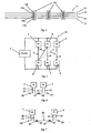
- FIG. 1 a monitoring system 1 consisting of a sensor network 2 and a controller 3 is shown. A multiplicity of pairs of transmitters 4 and receivers 5 are arranged in the sensor network 2.
- Each transmitter 4 and each receiver 5 is preferably designed as a separate structural unit. All transmitters and receivers 4, 5 are connected to the controller 3.
- the transmitters 4 emit, for example, light, in particular infrared light, which is received by the opposite receiver of the respective receiver pair.
- a light beam is symbolized by an arrow 6 in each case.
- the transmitter 4 is connected to the controller via a connecting line 7.
- the receiver 5 is connected to the controller 3 by a connecting line 8.
- the controller 3 is able, for example, to sequentially assign the recipients 5 and the transmitters 4 address addresses, so that after the assignment by the sequential specification, a physical order and thus also the arrangement of receiver / transmitter pairs for corresponding processing by the controller 3 can be derived.
- a comparatively large monitoring area 6a can be monitored for existing or emerging objects.
- the sensors 4, 5 monitor the escalator for objects. After a power failure, the escalator can start up automatically, provided that sensors 4, 5 do not detect an object in the monitored area 6a.
- a connecting line 9 is shown, to which transmitter or receiver 4, 5 are electrically connected.
- the connecting line 9 is, for example, three-wire, with two wires 10, 11 serving for the power supply and a third wire 12 being used as a data line.
- the receiver 5 or transmitter 4 is addressed by the controller 3 via the data line 12 in order to transmit a signal or, if it is the receiver 5, to carry out an evaluation.
- connection line 9 The wires 10 and 11 of the connection line 9 are as shown in Figure 2 the power supply for the respective receiver / transmitter 4, 5 is available.
- the data line 12 is, however, interrupted by the respective receiver / transmitter 4, 5. If, for example, an activation signal is sent via the data line 12, which arrives at the first transmitter 4, whereby this is switched to active, a signal is transmitted. When activated, a receiver supplies an evaluation signal, for example.
- the transmitter or receiver coming closest to the data line 12 is activated, and the previously activated transmitter or receiver is deactivated again.
- FIG. 4 shows a schematic representation of a bus line 13, four wires 14-17.
- Plug elements 18 are placed on the bus line, for example clipped on, without interrupting the bus line 13, the plug elements 18 providing a connection contact 14a to 17a for each wire 14-17.
- a receiver 5 or transmitter 4 can be plugged into such a plug element in a simple manner by means of a suitable counterpart.
- the distances between the plug elements 18 can be designed individually for the desired positioning of the sensors.
- a monitoring system 19 which comprises pairs of transmitters 4 and receivers 5 for generating monitoring light beams 6, the pairs of transmitter 4 and receiver 5 being arranged alternately, so that on one side a transmitter 4 is followed by a receiver 5 and on the receiver 5 in turn is a transmitter 4.
- a transmitter 4 also finds a transmitter 4 on the opposite side, adjacent to the associated receiver 5, which a crosstalk light beam 20, i.e. a light beam that does not run to the associated receiver 5, leaves unaffected.
- a light beam 21 would have to be created so that a receiver 5 next but one is hit.
- Such a strong crosstalk behavior is, however, unlikely with appropriate dimensioning, so that a higher security in the monitoring can be achieved with this arrangement.
- FIGS. 6 and 7 show two connection examples for transmitter 4 and receiver 5.
- Each transmitter 4 and receiver 5 has two connection lines z22, 23, at the ends of which a connector element 24, 25 is connected.
- the plug elements 24, 25 are preferably designed in such a way that only a meaningful connection to a transmitter and / or receiver can be established.
- the receiver 5 was electrically connected to a transmitter 4.
- connection cables 26 are also conceivable which are equipped with corresponding plug elements 24, 25.
- Such a network is in Figure 7 pictured.
- the plug elements are preferably designed in such a way that only predetermined combinations are possible, e.g. plug element 24 can only be combined with one plug element 25. This can prevent incorrect connections.
- Figure 8 the aspect of the invention which relates to the distribution of addresses to bus subscribers 27, 28, 29, for example receivers or transmitters, on a data bus 30 should be clarified.
- the three bus users 27, 28, 29 are connected to a controller 31 via the data bus 30.
- neighboring bus users are connected to one another via a connection 32.
- the bus subscribers 27, 28, 29 are not assigned any addresses.
- the bus users 27, 28, 29 have switching units 33, 34, 35.
- the switching unit 33, 34, 35 is in a switching state that a terminating element, e.g. a terminating resistor 36, electrically terminates the bus.
- a terminating element e.g. a terminating resistor 36
- the further bus subscriber 29 is decoupled from the bus by the switch position of the switching unit 34.
- the controller 31 can thus communicate with the bus subscriber 27 and the bus subscriber 28. To assign addresses, the controller 31 sends corresponding information to all bus users who have not yet received an address. According to Figure 8 can he Bus subscribers 28 receive this information. The further bus participant 29 is separated from the bus. The bus subscriber 27 has already received an address.
- the switching unit 33 As soon as a bus subscriber has received an address, the switching unit 33 is brought into a switching position, as shown in the bus subscriber 27, so that the next following bus subscriber, in the present case the bus subscriber 28, can be addressed for addressing. Exactly this state is in Figure 8 shown. What is achieved in this way is that the bus subscribers can automatically be provided with an address and, as a result, the physical sequence of the bus subscribers is inevitably available to the controller 31.
- the terminating resistor of the last module can be adjusted by taking appropriate measures, for example by means of a timer or from the analysis of the communication that takes place on the bus 36 switch on again.
- the switching unit 33, 34, 35 is only switched over when a bus subscriber has received an address and also receives a signal from a neighbor. The last bus subscriber in the sequence is thus addressed, but the switching unit 35 is left in the switching position that connects the terminating resistor 36 to the data bus 30.
Landscapes
- Physics & Mathematics (AREA)
- Life Sciences & Earth Sciences (AREA)
- Engineering & Computer Science (AREA)
- Remote Sensing (AREA)
- General Life Sciences & Earth Sciences (AREA)
- General Physics & Mathematics (AREA)
- Geophysics (AREA)
- Acoustics & Sound (AREA)
- Environmental & Geological Engineering (AREA)
- Geology (AREA)
- Multimedia (AREA)
- Arrangements For Transmission Of Measured Signals (AREA)
- Alarm Systems (AREA)
Claims (12)
- Système (1, 19) de détection d'un objet sur une surface de surveillance (6a), comportant une pluralité de capteurs (4, 5) constitués d'au moins un émetteur (4) et d'au moins un récepteur (5), ainsi qu'une unité électronique (3) pour l'évaluation des récepteurs (5), caractérisé en ce que les émetteurs et les récepteurs sont aptes aux bus et sont reliés par l'intermédiaire d'un système de bus à l'unité électronique, en ce que l'unité électronique est capable d'affecter une adresse de contact aux émetteurs et aux récepteurs, une affectation d'adresse étant réalisée de telle manière qu'après affectation de l'adresse, il est possible d'associer les récepteurs aux émetteurs et après la distribution des adresses la suite physique des émetteurs et des récepteurs de l'unité électronique est à disposition.
- Système selon la revendication 1, caractérisé en ce que les émetteurs (4) et/ou les récepteurs (5) sont disposés dans des unités modulaires séparées.
- Système selon l'une des revendications précédentes, caractérisé en ce que l'unité électronique (3) est conçue pour évaluer des récepteurs (5) de façon sélective.
- Système selon l'une des revendications précédentes, caractérisé en ce que les récepteurs (5) sont conçus pour produire un signal d'identification d'objet spécifique au récepteur.
- Système selon l'une des revendications précédentes, caractérisé en ce que l'unité électronique (3) est conçue pour s'adresser de façon séquentielle aux récepteurs (5) en vue d'une évaluation.
- Système selon l'une des revendications précédentes, caractérisé en ce que l'unité électronique (3) est conçue pour évaluer des motifs selon l'ordre dans lequel les récepteurs (5) détectent un objet.
- Système selon l'une des revendications précédentes, caractérisé en ce que les récepteurs (5) fonctionnent sur la base d'une lumière.
- Système selon l'une des revendications précédentes, caractérisé en ce que les récepteurs (5) fonctionnent sur la base d'ultrasons.
- Système selon l'une des revendications précédentes, caractérisé en ce que les récepteurs (5) et/ou les émetteurs (4) sont reliés ensemble par des connecteurs enfichables (18).
- Système selon l'une des revendications précédentes, caractérisé en ce que l'unité électronique (3) comporte des moyens d'affichage qui affichent quel récepteur (5) détecte un objet.
- Système selon l'une des revendications précédentes, caractérisé en ce que l'unité électronique est conçue pour pouvoir commander de manière ciblée des émetteurs (4).
- Système selon l'une des revendications précédentes, caractérisé en ce que les émetteurs (4) et les récepteurs (5) sont disposés les uns en face des autres, les émetteurs (4) et les récepteurs (5) étant situés chacun sur des côtés différents.
Applications Claiming Priority (3)
| Application Number | Priority Date | Filing Date | Title |
|---|---|---|---|
| DE102007053557 | 2007-11-07 | ||
| DE102008028280 | 2008-06-16 | ||
| PCT/EP2008/009412 WO2009059782A1 (fr) | 2007-11-07 | 2008-11-07 | Système de détection d'un objet sur une surface de surveillance |
Publications (3)
| Publication Number | Publication Date |
|---|---|
| EP2208092A1 EP2208092A1 (fr) | 2010-07-21 |
| EP2208092B1 EP2208092B1 (fr) | 2014-01-29 |
| EP2208092B2 true EP2208092B2 (fr) | 2021-09-15 |
Family
ID=40328853
Family Applications (1)
| Application Number | Title | Priority Date | Filing Date |
|---|---|---|---|
| EP08846417.7A Active EP2208092B2 (fr) | 2007-11-07 | 2008-11-07 | Système de détection d'un objet sur une surface de surveillance |
Country Status (4)
| Country | Link |
|---|---|
| US (1) | US20100245117A1 (fr) |
| EP (1) | EP2208092B2 (fr) |
| DE (1) | DE102008056458A1 (fr) |
| WO (1) | WO2009059782A1 (fr) |
Families Citing this family (6)
| Publication number | Priority date | Publication date | Assignee | Title |
|---|---|---|---|---|
| WO2011088514A1 (fr) * | 2010-01-22 | 2011-07-28 | Smart Openers Pty Ltd | Système de protection à faisceau pour dispositif d'actionnement de porte |
| DE102012101369B4 (de) * | 2012-02-21 | 2022-05-12 | Leuze Electronic Gmbh & Co. Kg | Lichtvorhang |
| EP2796903B1 (fr) * | 2013-04-24 | 2018-12-26 | Rockwell Automation Safety AG | Unité optique, rideau de lumière et procédé pour attribuer une adresse individuelle |
| EP2808706B1 (fr) * | 2013-05-28 | 2023-06-28 | Rockwell Automation Switzerland GmbH | Élément émetteur/récepteur pour une unité optique d'une barrière photoélectrique et rideau de lumière photoélectrique |
| DE202014102335U1 (de) | 2014-05-19 | 2015-08-24 | Sick Ag | Sensorsystem |
| EP3441796B1 (fr) | 2017-08-11 | 2021-04-21 | Sick Ag | Système de capteurs |
Family Cites Families (23)
| Publication number | Priority date | Publication date | Assignee | Title |
|---|---|---|---|---|
| US4301447A (en) * | 1979-12-12 | 1981-11-17 | Sperry Corporation | Scan control for light beam position indicator |
| FR2603386B1 (fr) * | 1986-09-03 | 1989-03-10 | Cometa Sa | Procede et appareil de surveillance par recoupement de faisceaux lumineux |
| US5567931A (en) * | 1994-10-25 | 1996-10-22 | Otis Elevator Company | Variable beam detection using a dynamic detection threshold |
| DE19500822C1 (de) * | 1995-01-13 | 1996-03-21 | Erhardt & Leimer Gmbh | Ultraschall-Kantenfühler zur Erfassung der Bahnkante einer Warenbahn |
| US5814771A (en) * | 1996-02-16 | 1998-09-29 | Structural Instrumentation, Inc. | On-board microprocessor controlled load weighing system |
| DE19861128B4 (de) * | 1997-04-21 | 2006-11-16 | Leuze Electronic Gmbh & Co Kg | Optischer Türwächter |
| US6624750B1 (en) * | 1998-10-06 | 2003-09-23 | Interlogix, Inc. | Wireless home fire and security alarm system |
| GB9901300D0 (en) * | 1999-01-22 | 1999-03-10 | Olivetti Research Ltd | A method of increasing the capacity and addressing rate of an Ultrasonic location system |
| US6175419B1 (en) * | 1999-03-24 | 2001-01-16 | Fife Corporation | Light sensor for web-guiding apparatus |
| EP1234225B1 (fr) * | 1999-12-02 | 2011-11-02 | Tyco Electronics Corporation | Appareil et procede permettant d'ameliorer la resolution des systemes tactiles a infrarouge |
| US6635862B2 (en) * | 2000-03-10 | 2003-10-21 | Scientific Technologies Incorporated | Mixed architecture light curtain system |
| US6495832B1 (en) * | 2000-03-15 | 2002-12-17 | Touch Controls, Inc. | Photoelectric sensing array apparatus and method of using same |
| US6267219B1 (en) * | 2000-08-11 | 2001-07-31 | Otis Elevator Company | Electronic safety system for escalators |
| WO2002103935A1 (fr) * | 2001-06-15 | 2002-12-27 | Al-Chalabi Salah A | Dispositif et systeme de communication optique |
| US6987450B2 (en) * | 2002-10-02 | 2006-01-17 | Honeywell International Inc. | Method and apparatus for determining message response type in a security system |
| DE10342836A1 (de) * | 2003-09-17 | 2005-04-28 | Adc Automotive Dist Control | Umgebungserfassungssystem mit zwei beabstandeten Sendern und Empfängern |
| US20050108098A1 (en) * | 2003-11-13 | 2005-05-19 | Majid Syed | Network controlled retail shelf display receiver system and method |
| DE202004000893U1 (de) * | 2004-01-21 | 2004-04-01 | Thyssenkrupp Fahrtreppen Gmbh | Fahrtreppe oder Fahrsteig |
| US7415881B2 (en) * | 2004-08-19 | 2008-08-26 | Fife Corporation | Ultrasonic sensor system for web-guiding apparatus |
| US7369060B2 (en) * | 2004-12-14 | 2008-05-06 | Lutron Electronics Co., Inc. | Distributed intelligence ballast system and extended lighting control protocol |
| CN1828118B (zh) * | 2005-03-01 | 2011-05-25 | 海德堡印刷机械股份公司 | 具有单独的输出信号的光电栅栏 |
| DE102006059322B4 (de) * | 2006-12-15 | 2009-03-26 | Leuze Lumiflex Gmbh + Co. Kg | Verfahren zur Erfassung von Objekten in einem Überwachungsbereich mittels eines Lichtgitters |
| DE102007024210A1 (de) * | 2007-05-15 | 2008-11-27 | Pilz Gmbh & Co. Kg | Optoelektronischer Sensor zum Absichern eines Gefahrenbereichs |
-
2008
- 2008-11-07 EP EP08846417.7A patent/EP2208092B2/fr active Active
- 2008-11-07 DE DE102008056458A patent/DE102008056458A1/de not_active Withdrawn
- 2008-11-07 WO PCT/EP2008/009412 patent/WO2009059782A1/fr not_active Ceased
-
2010
- 2010-05-06 US US12/774,797 patent/US20100245117A1/en not_active Abandoned
Also Published As
| Publication number | Publication date |
|---|---|
| DE102008056458A1 (de) | 2009-07-23 |
| EP2208092A1 (fr) | 2010-07-21 |
| EP2208092B1 (fr) | 2014-01-29 |
| WO2009059782A1 (fr) | 2009-05-14 |
| US20100245117A1 (en) | 2010-09-30 |
Similar Documents
| Publication | Publication Date | Title |
|---|---|---|
| EP2147338B1 (fr) | Détecteur optoélectronique permettant de sécuriser une zone dangereuse | |
| EP2208092B1 (fr) | Système de détection d'un objet sur une surface de surveillance | |
| EP2866387B1 (fr) | Système de bus et procédé de fonctionnement d'un tel système de bus | |
| EP1870734B1 (fr) | Rideau de lumière opto-électronique avec au moins deux barres de transmission/réception | |
| EP2000866B1 (fr) | Dispositif de surveillance destiné à la reconnaissance d'un adressage incorrect d'un esclave dans un système de bus de terrain | |
| DE102011087152B4 (de) | Testsystem und Testverfahren für Kabelbäume | |
| DE102018129835A1 (de) | Steuerungssystem, Kopplermodul und Verfahren zur Montage eines Steuerungssystems | |
| DE10147512A1 (de) | Verfahren zur Adressierung der Teilnehmer eines Bussystems | |
| EP3436383B1 (fr) | Ascenseur comprenant une unite de commande centrale et plusieurs appareils de champ communiquant selon un procede de trame unique | |
| DE202010000110U1 (de) | Eigensichere Anschlusseinheit mit Netzwerk-Schnittstelle, eigensicheres Gerät und Netzwerk-Schnittstelle hierfür | |
| DE102012220402B4 (de) | Sensorsystem für Baugeräte mit drahtlosen Schallsensorsystemen | |
| WO2005053221A2 (fr) | Reseau, notamment reseau pa profibus, a proprietes de redondance, element de ramification pour appareil d'abonne dans un reseau de ce type, gestionnaire de redondance pour un reseau de ce type et procede pour faire fonctionner un reseau de ce type | |
| EP1875674B1 (fr) | Procede et dispositifs pour la transmission de donnees sur une ligne de donnees entre un appareil de commande et au moins un appareil de traitement de donnees decentralise | |
| DE102015013442A1 (de) | Automatisches Ermitteln von Verbaupositionen elektrischer Fahrzeugkomponenten in einem Kraftfahrzeug | |
| EP2845392B1 (fr) | Procédé pour la surveillance du fonctionnement d'une unité de réception psi5 d'un appareil de commande de véhicule automobile, ainsi qu'unité de réception psi5 correspondante | |
| EP3024180A1 (fr) | Reseau et procede destine au fonctionnement d'un reseau | |
| DE102017116385B3 (de) | Feldbussystem | |
| DE102009050692B4 (de) | Sicherheits-Kommunikationssystem zur Signalisierung von Systemzuständen | |
| WO2018215301A1 (fr) | Émission de signal d'état | |
| EP1377798B1 (fr) | Procede servant a attenuer les interactions dans un systeme optique a detecteurs multiples, et systeme de detection multiple correspondant | |
| DE102017128249B4 (de) | Anordnung für einen Aktuator-Sensor Interface Feldbus (AS-i-Bus) mit einem Diagnosegerät | |
| DE102004030767A1 (de) | AS-Interface-Netzwerk für große Entfernungen | |
| DE102006018281B4 (de) | Verfahren zum Installieren eines Funksystems in einem Gebäude | |
| DE19902490A1 (de) | Messeanordnung und Messverfahren | |
| DE102005048548B4 (de) | Vorrichtung zur Datenübertragung und Busstation zur Datenübertragung an ein Steuergerät |
Legal Events
| Date | Code | Title | Description |
|---|---|---|---|
| PUAI | Public reference made under article 153(3) epc to a published international application that has entered the european phase |
Free format text: ORIGINAL CODE: 0009012 |
|
| 17P | Request for examination filed |
Effective date: 20100305 |
|
| AK | Designated contracting states |
Kind code of ref document: A1 Designated state(s): AT BE BG CH CY CZ DE DK EE ES FI FR GB GR HR HU IE IS IT LI LT LU LV MC MT NL NO PL PT RO SE SI SK TR |
|
| AX | Request for extension of the european patent |
Extension state: AL BA MK RS |
|
| DAX | Request for extension of the european patent (deleted) | ||
| 17Q | First examination report despatched |
Effective date: 20121109 |
|
| GRAP | Despatch of communication of intention to grant a patent |
Free format text: ORIGINAL CODE: EPIDOSNIGR1 |
|
| INTG | Intention to grant announced |
Effective date: 20130909 |
|
| GRAS | Grant fee paid |
Free format text: ORIGINAL CODE: EPIDOSNIGR3 |
|
| GRAA | (expected) grant |
Free format text: ORIGINAL CODE: 0009210 |
|
| AK | Designated contracting states |
Kind code of ref document: B1 Designated state(s): AT BE BG CH CY CZ DE DK EE ES FI FR GB GR HR HU IE IS IT LI LT LU LV MC MT NL NO PL PT RO SE SI SK TR |
|
| REG | Reference to a national code |
Ref country code: GB Ref legal event code: FG4D Free format text: NOT ENGLISH |
|
| REG | Reference to a national code |
Ref country code: CH Ref legal event code: EP |
|
| REG | Reference to a national code |
Ref country code: AT Ref legal event code: REF Ref document number: 651624 Country of ref document: AT Kind code of ref document: T Effective date: 20140215 |
|
| REG | Reference to a national code |
Ref country code: IE Ref legal event code: FG4D Free format text: LANGUAGE OF EP DOCUMENT: GERMAN |
|
| REG | Reference to a national code |
Ref country code: DE Ref legal event code: R096 Ref document number: 502008011295 Country of ref document: DE Effective date: 20140313 |
|
| REG | Reference to a national code |
Ref country code: CH Ref legal event code: NV Representative=s name: KELLER AND PARTNER PATENTANWAELTE AG, CH |
|
| REG | Reference to a national code |
Ref country code: NL Ref legal event code: VDEP Effective date: 20140129 |
|
| REG | Reference to a national code |
Ref country code: LT Ref legal event code: MG4D |
|
| PG25 | Lapsed in a contracting state [announced via postgrant information from national office to epo] |
Ref country code: LT Free format text: LAPSE BECAUSE OF FAILURE TO SUBMIT A TRANSLATION OF THE DESCRIPTION OR TO PAY THE FEE WITHIN THE PRESCRIBED TIME-LIMIT Effective date: 20140129 Ref country code: NO Free format text: LAPSE BECAUSE OF FAILURE TO SUBMIT A TRANSLATION OF THE DESCRIPTION OR TO PAY THE FEE WITHIN THE PRESCRIBED TIME-LIMIT Effective date: 20140429 Ref country code: IS Free format text: LAPSE BECAUSE OF FAILURE TO SUBMIT A TRANSLATION OF THE DESCRIPTION OR TO PAY THE FEE WITHIN THE PRESCRIBED TIME-LIMIT Effective date: 20140529 |
|
| PG25 | Lapsed in a contracting state [announced via postgrant information from national office to epo] |
Ref country code: SE Free format text: LAPSE BECAUSE OF FAILURE TO SUBMIT A TRANSLATION OF THE DESCRIPTION OR TO PAY THE FEE WITHIN THE PRESCRIBED TIME-LIMIT Effective date: 20140129 Ref country code: CY Free format text: LAPSE BECAUSE OF FAILURE TO SUBMIT A TRANSLATION OF THE DESCRIPTION OR TO PAY THE FEE WITHIN THE PRESCRIBED TIME-LIMIT Effective date: 20140129 Ref country code: NL Free format text: LAPSE BECAUSE OF FAILURE TO SUBMIT A TRANSLATION OF THE DESCRIPTION OR TO PAY THE FEE WITHIN THE PRESCRIBED TIME-LIMIT Effective date: 20140129 Ref country code: FI Free format text: LAPSE BECAUSE OF FAILURE TO SUBMIT A TRANSLATION OF THE DESCRIPTION OR TO PAY THE FEE WITHIN THE PRESCRIBED TIME-LIMIT Effective date: 20140129 Ref country code: PT Free format text: LAPSE BECAUSE OF FAILURE TO SUBMIT A TRANSLATION OF THE DESCRIPTION OR TO PAY THE FEE WITHIN THE PRESCRIBED TIME-LIMIT Effective date: 20140529 Ref country code: ES Free format text: LAPSE BECAUSE OF FAILURE TO SUBMIT A TRANSLATION OF THE DESCRIPTION OR TO PAY THE FEE WITHIN THE PRESCRIBED TIME-LIMIT Effective date: 20140129 |
|
| PG25 | Lapsed in a contracting state [announced via postgrant information from national office to epo] |
Ref country code: LV Free format text: LAPSE BECAUSE OF FAILURE TO SUBMIT A TRANSLATION OF THE DESCRIPTION OR TO PAY THE FEE WITHIN THE PRESCRIBED TIME-LIMIT Effective date: 20140129 Ref country code: HR Free format text: LAPSE BECAUSE OF FAILURE TO SUBMIT A TRANSLATION OF THE DESCRIPTION OR TO PAY THE FEE WITHIN THE PRESCRIBED TIME-LIMIT Effective date: 20140129 |
|
| REG | Reference to a national code |
Ref country code: DE Ref legal event code: R026 Ref document number: 502008011295 Country of ref document: DE |
|
| PLBI | Opposition filed |
Free format text: ORIGINAL CODE: 0009260 |
|
| PG25 | Lapsed in a contracting state [announced via postgrant information from national office to epo] |
Ref country code: CZ Free format text: LAPSE BECAUSE OF FAILURE TO SUBMIT A TRANSLATION OF THE DESCRIPTION OR TO PAY THE FEE WITHIN THE PRESCRIBED TIME-LIMIT Effective date: 20140129 Ref country code: DK Free format text: LAPSE BECAUSE OF FAILURE TO SUBMIT A TRANSLATION OF THE DESCRIPTION OR TO PAY THE FEE WITHIN THE PRESCRIBED TIME-LIMIT Effective date: 20140129 Ref country code: EE Free format text: LAPSE BECAUSE OF FAILURE TO SUBMIT A TRANSLATION OF THE DESCRIPTION OR TO PAY THE FEE WITHIN THE PRESCRIBED TIME-LIMIT Effective date: 20140129 Ref country code: RO Free format text: LAPSE BECAUSE OF FAILURE TO SUBMIT A TRANSLATION OF THE DESCRIPTION OR TO PAY THE FEE WITHIN THE PRESCRIBED TIME-LIMIT Effective date: 20140129 |
|
| PLBI | Opposition filed |
Free format text: ORIGINAL CODE: 0009260 |
|
| 26 | Opposition filed |
Opponent name: SICK AG Effective date: 20141023 |
|
| PG25 | Lapsed in a contracting state [announced via postgrant information from national office to epo] |
Ref country code: SK Free format text: LAPSE BECAUSE OF FAILURE TO SUBMIT A TRANSLATION OF THE DESCRIPTION OR TO PAY THE FEE WITHIN THE PRESCRIBED TIME-LIMIT Effective date: 20140129 Ref country code: PL Free format text: LAPSE BECAUSE OF FAILURE TO SUBMIT A TRANSLATION OF THE DESCRIPTION OR TO PAY THE FEE WITHIN THE PRESCRIBED TIME-LIMIT Effective date: 20140129 |
|
| 26 | Opposition filed |
Opponent name: LEUZE ELECTRONIC GMBH + CO. KG Effective date: 20141024 |
|
| PLAX | Notice of opposition and request to file observation + time limit sent |
Free format text: ORIGINAL CODE: EPIDOSNOBS2 |
|
| REG | Reference to a national code |
Ref country code: DE Ref legal event code: R026 Ref document number: 502008011295 Country of ref document: DE Effective date: 20141023 |
|
| REG | Reference to a national code |
Ref country code: CH Ref legal event code: PCAR Free format text: NEW ADDRESS: EIGERSTRASSE 2 POSTFACH, 3000 BERN 14 (CH) |
|
| PLBB | Reply of patent proprietor to notice(s) of opposition received |
Free format text: ORIGINAL CODE: EPIDOSNOBS3 |
|
| PG25 | Lapsed in a contracting state [announced via postgrant information from national office to epo] |
Ref country code: SI Free format text: LAPSE BECAUSE OF FAILURE TO SUBMIT A TRANSLATION OF THE DESCRIPTION OR TO PAY THE FEE WITHIN THE PRESCRIBED TIME-LIMIT Effective date: 20140129 |
|
| PG25 | Lapsed in a contracting state [announced via postgrant information from national office to epo] |
Ref country code: BE Free format text: LAPSE BECAUSE OF NON-PAYMENT OF DUE FEES Effective date: 20141130 Ref country code: MC Free format text: LAPSE BECAUSE OF FAILURE TO SUBMIT A TRANSLATION OF THE DESCRIPTION OR TO PAY THE FEE WITHIN THE PRESCRIBED TIME-LIMIT Effective date: 20140129 Ref country code: LU Free format text: LAPSE BECAUSE OF FAILURE TO SUBMIT A TRANSLATION OF THE DESCRIPTION OR TO PAY THE FEE WITHIN THE PRESCRIBED TIME-LIMIT Effective date: 20141107 |
|
| GBPC | Gb: european patent ceased through non-payment of renewal fee |
Effective date: 20141107 |
|
| REG | Reference to a national code |
Ref country code: IE Ref legal event code: MM4A |
|
| REG | Reference to a national code |
Ref country code: FR Ref legal event code: ST Effective date: 20150731 |
|
| PG25 | Lapsed in a contracting state [announced via postgrant information from national office to epo] |
Ref country code: IE Free format text: LAPSE BECAUSE OF NON-PAYMENT OF DUE FEES Effective date: 20141107 Ref country code: GB Free format text: LAPSE BECAUSE OF NON-PAYMENT OF DUE FEES Effective date: 20141107 |
|
| PG25 | Lapsed in a contracting state [announced via postgrant information from national office to epo] |
Ref country code: FR Free format text: LAPSE BECAUSE OF NON-PAYMENT OF DUE FEES Effective date: 20141201 |
|
| REG | Reference to a national code |
Ref country code: AT Ref legal event code: MM01 Ref document number: 651624 Country of ref document: AT Kind code of ref document: T Effective date: 20141107 |
|
| PG25 | Lapsed in a contracting state [announced via postgrant information from national office to epo] |
Ref country code: AT Free format text: LAPSE BECAUSE OF NON-PAYMENT OF DUE FEES Effective date: 20141107 |
|
| PG25 | Lapsed in a contracting state [announced via postgrant information from national office to epo] |
Ref country code: BG Free format text: LAPSE BECAUSE OF FAILURE TO SUBMIT A TRANSLATION OF THE DESCRIPTION OR TO PAY THE FEE WITHIN THE PRESCRIBED TIME-LIMIT Effective date: 20140129 |
|
| PG25 | Lapsed in a contracting state [announced via postgrant information from national office to epo] |
Ref country code: GR Free format text: LAPSE BECAUSE OF FAILURE TO SUBMIT A TRANSLATION OF THE DESCRIPTION OR TO PAY THE FEE WITHIN THE PRESCRIBED TIME-LIMIT Effective date: 20140430 Ref country code: IT Free format text: LAPSE BECAUSE OF FAILURE TO SUBMIT A TRANSLATION OF THE DESCRIPTION OR TO PAY THE FEE WITHIN THE PRESCRIBED TIME-LIMIT Effective date: 20140129 |
|
| RIC2 | Information provided on ipc code assigned after grant |
Ipc: G10K 11/26 20060101ALI20160606BHEP Ipc: G01V 1/145 20060101AFI20160606BHEP |
|
| APBM | Appeal reference recorded |
Free format text: ORIGINAL CODE: EPIDOSNREFNO |
|
| APBP | Date of receipt of notice of appeal recorded |
Free format text: ORIGINAL CODE: EPIDOSNNOA2O |
|
| APAH | Appeal reference modified |
Free format text: ORIGINAL CODE: EPIDOSCREFNO |
|
| PG25 | Lapsed in a contracting state [announced via postgrant information from national office to epo] |
Ref country code: MT Free format text: LAPSE BECAUSE OF FAILURE TO SUBMIT A TRANSLATION OF THE DESCRIPTION OR TO PAY THE FEE WITHIN THE PRESCRIBED TIME-LIMIT Effective date: 20140129 Ref country code: HU Free format text: LAPSE BECAUSE OF FAILURE TO SUBMIT A TRANSLATION OF THE DESCRIPTION OR TO PAY THE FEE WITHIN THE PRESCRIBED TIME-LIMIT; INVALID AB INITIO Effective date: 20081107 Ref country code: TR Free format text: LAPSE BECAUSE OF FAILURE TO SUBMIT A TRANSLATION OF THE DESCRIPTION OR TO PAY THE FEE WITHIN THE PRESCRIBED TIME-LIMIT Effective date: 20140129 |
|
| APBM | Appeal reference recorded |
Free format text: ORIGINAL CODE: EPIDOSNREFNO |
|
| APBP | Date of receipt of notice of appeal recorded |
Free format text: ORIGINAL CODE: EPIDOSNNOA2O |
|
| APBQ | Date of receipt of statement of grounds of appeal recorded |
Free format text: ORIGINAL CODE: EPIDOSNNOA3O |
|
| APBQ | Date of receipt of statement of grounds of appeal recorded |
Free format text: ORIGINAL CODE: EPIDOSNNOA3O |
|
| REG | Reference to a national code |
Ref country code: CH Ref legal event code: PFA Owner name: CEDES AG, CH Free format text: FORMER OWNER: CEDES AG, CH |
|
| APBU | Appeal procedure closed |
Free format text: ORIGINAL CODE: EPIDOSNNOA9O |
|
| REG | Reference to a national code |
Ref country code: CH Ref legal event code: PK Free format text: BERICHTIGUNGEN |
|
| RIC2 | Information provided on ipc code assigned after grant |
Ipc: G01V 8/20 20060101AFI20210429BHEP |
|
| PUAH | Patent maintained in amended form |
Free format text: ORIGINAL CODE: 0009272 |
|
| STAA | Information on the status of an ep patent application or granted ep patent |
Free format text: STATUS: PATENT MAINTAINED AS AMENDED |
|
| 27A | Patent maintained in amended form |
Effective date: 20210915 |
|
| AK | Designated contracting states |
Kind code of ref document: B2 Designated state(s): AT BE BG CH CY CZ DE DK EE ES FI FR GB GR HR HU IE IS IT LI LT LU LV MC MT NL NO PL PT RO SE SI SK TR |
|
| REG | Reference to a national code |
Ref country code: DE Ref legal event code: R102 Ref document number: 502008011295 Country of ref document: DE |
|
| PGFP | Annual fee paid to national office [announced via postgrant information from national office to epo] |
Ref country code: DE Payment date: 20221121 Year of fee payment: 15 |
|
| PGFP | Annual fee paid to national office [announced via postgrant information from national office to epo] |
Ref country code: CH Payment date: 20221124 Year of fee payment: 15 |
|
| P01 | Opt-out of the competence of the unified patent court (upc) registered |
Effective date: 20230519 |
|
| REG | Reference to a national code |
Ref country code: DE Ref legal event code: R119 Ref document number: 502008011295 Country of ref document: DE |
|
| REG | Reference to a national code |
Ref country code: CH Ref legal event code: PL |
|
| PG25 | Lapsed in a contracting state [announced via postgrant information from national office to epo] |
Ref country code: CH Free format text: LAPSE BECAUSE OF NON-PAYMENT OF DUE FEES Effective date: 20231130 |
|
| PG25 | Lapsed in a contracting state [announced via postgrant information from national office to epo] |
Ref country code: CH Free format text: LAPSE BECAUSE OF NON-PAYMENT OF DUE FEES Effective date: 20231130 |
|
| PG25 | Lapsed in a contracting state [announced via postgrant information from national office to epo] |
Ref country code: DE Free format text: LAPSE BECAUSE OF NON-PAYMENT OF DUE FEES Effective date: 20240601 |
|
| PG25 | Lapsed in a contracting state [announced via postgrant information from national office to epo] |
Ref country code: DE Free format text: LAPSE BECAUSE OF NON-PAYMENT OF DUE FEES Effective date: 20240601 |