EP2208412A2 - Construction de coupure améliorée pour ensemble de ventilateur transversal - Google Patents
Construction de coupure améliorée pour ensemble de ventilateur transversal Download PDFInfo
- Publication number
- EP2208412A2 EP2208412A2 EP10150669A EP10150669A EP2208412A2 EP 2208412 A2 EP2208412 A2 EP 2208412A2 EP 10150669 A EP10150669 A EP 10150669A EP 10150669 A EP10150669 A EP 10150669A EP 2208412 A2 EP2208412 A2 EP 2208412A2
- Authority
- EP
- European Patent Office
- Prior art keywords
- fan
- generally
- construction
- cut
- transverse
- Prior art date
- Legal status (The legal status is an assumption and is not a legal conclusion. Google has not performed a legal analysis and makes no representation as to the accuracy of the status listed.)
- Granted
Links
Images



Classifications
-
- A—HUMAN NECESSITIES
- A01—AGRICULTURE; FORESTRY; ANIMAL HUSBANDRY; HUNTING; TRAPPING; FISHING
- A01F—PROCESSING OF HARVESTED PRODUCE; HAY OR STRAW PRESSES; DEVICES FOR STORING AGRICULTURAL OR HORTICULTURAL PRODUCE
- A01F12/00—Parts or details of threshing apparatus
- A01F12/44—Grain cleaners; Grain separators
- A01F12/444—Fanning means
-
- F—MECHANICAL ENGINEERING; LIGHTING; HEATING; WEAPONS; BLASTING
- F04—POSITIVE - DISPLACEMENT MACHINES FOR LIQUIDS; PUMPS FOR LIQUIDS OR ELASTIC FLUIDS
- F04D—NON-POSITIVE-DISPLACEMENT PUMPS
- F04D17/00—Radial-flow pumps, e.g. centrifugal pumps; Helico-centrifugal pumps
- F04D17/02—Radial-flow pumps, e.g. centrifugal pumps; Helico-centrifugal pumps having non-centrifugal stages, e.g. centripetal
- F04D17/04—Radial-flow pumps, e.g. centrifugal pumps; Helico-centrifugal pumps having non-centrifugal stages, e.g. centripetal of transverse-flow type
-
- F—MECHANICAL ENGINEERING; LIGHTING; HEATING; WEAPONS; BLASTING
- F04—POSITIVE - DISPLACEMENT MACHINES FOR LIQUIDS; PUMPS FOR LIQUIDS OR ELASTIC FLUIDS
- F04D—NON-POSITIVE-DISPLACEMENT PUMPS
- F04D29/00—Details, component parts, or accessories
- F04D29/40—Casings; Connections of working fluid
- F04D29/42—Casings; Connections of working fluid for radial or helico-centrifugal pumps
- F04D29/4206—Casings; Connections of working fluid for radial or helico-centrifugal pumps especially adapted for elastic fluid pumps
- F04D29/422—Discharge tongues
-
- F—MECHANICAL ENGINEERING; LIGHTING; HEATING; WEAPONS; BLASTING
- F05—INDEXING SCHEMES RELATING TO ENGINES OR PUMPS IN VARIOUS SUBCLASSES OF CLASSES F01-F04
- F05D—INDEXING SCHEME FOR ASPECTS RELATING TO NON-POSITIVE-DISPLACEMENT MACHINES OR ENGINES, GAS-TURBINES OR JET-PROPULSION PLANTS
- F05D2250/00—Geometry
- F05D2250/70—Shape
Definitions
- the present invention relates generally to an improved cut-off construction for transverse fan assemblies, particularly as such transverse fan assemblies are utilized with agricultural combine harvesters in grain cleaning systems, which transverse fan assemblies include a fan mounted generally cross-wise within an air plenum that has an air inlet, an air outlet, and an output throat from the downstream side of the fan towards the air outlet, with a baffle construction for separating the air inlet and air outlet, and wherein the fan has a plurality of elongated fan blades of arcuate cross-section disposed spaced from one another about the axis of the fan and extending generally along the expanse of the fan and about the axis of the fan.
- the improved cut-off construction is positioned generally adjacent to the fan on its downstream side to cut off and direct the flow of air from the fan towards the air outlet and is so formed and configured to permit the production by the transverse fan assembly with which the improved cut-off construction is employed of greater air flow volume at lower fan revolutions per minute and to increase the ability of the fan to carry a higher pressure load.
- Agricultural combines typically have employed a rotary threshing or separating system for separating and segregating the grain from such other crop elements or portions.
- rotary threshing or separating systems are so designed that, as threshing occurs, the resulting crop material is typically caused to fall or be conveyed to a clean grain and tailings conveying system, sometimes also referred to as a collecting and conveying system, or even more simply as a conveying system, for further processing, which processing typically includes the feeding of such resulting crop material from the rotary threshing or separating system onto an underlying vibratory cleaning system or onto one or more conveyors for conveyance to such a cleaning system.
- a clean grain and tailings conveying system sometimes also referred to as a collecting and conveying system, or even more simply as a conveying system
- the cleaning system typically includes a set of stacked sieves or shoes that are reciprocally moved, usually in the fore and aft directions, to separate or sift the grain from tailings and material other than grain (MOG).
- MOG material other than grain
- the laterally extending clean grain conveyance trough receives the clean grain conveyed thereto from the clean grain collecting troughs and typically has associated therewith a conveyance mechanism, often in the form of an auger extending therethrough, for moving and delivering the clean grain in such clean grain conveyance trough to an elevator that carries the clean grain up to a clean grain tank.
- a conveyance mechanism often in the form of an auger extending therethrough
- the vibration of the sieves air is blown upwardly and rearwardly through the sieves to carry lighter elements of the MOG, or chaff, away.
- the heavier elements and tailings that are too large to fall through the sieves and too heavy to be blown away are caused to be moved by the vibrations, generally rearwardly along the top surfaces of the sieves, towards and over rear edges of the sieves to fall onto a tailings pan located below and extending somewhat beyond such rear edges.
- the tailings pan similarly to the clean grain pan, feeds the tailings to an intersecting, cross, generally laterally extending, tailings conveyance trough, sometimes referred to as the tailings auger trough or, more simply, the tailings trough.
- the sidewardly extending tailings conveyance trough receives the tailings conveyed thereto from the tailings collecting pan and/or troughs and has a conveyance mechanism, often in the form of an auger extending therethrough, for moving and delivering the tailings to a tailings return conveyor operable for carrying the tailings upwardly, back to the cleaning or separating system of the combine, for reprocessing, including further threshing of the tailings.
- fans of various types including, by way of example, vane-type fans, paddle fans, and cross-flow fans of various designs, all of which are capable of producing air to be blown upwardly and rearwardly through the sieves to carry the chaff away from the grain and tailings deposited onto the cleaning system sieves
- Such chaff is typically blown into an optional chaff spreader, operable for distributing the chaff over a desired swath of the field from which the crop is cut, or directed into an optional chopper, operable for mixing the chaff with straw for chopping and distributing such mix, or simply directed downwardly onto the field through a rear opening of the combine.
- Transverse or cross-flow fan assemblies are well known in the art, and such fan assemblies typically have included axially spaced disk-like members that support a plurality of elongated fan blades in some form of cylindrical pattern or array, often with as many as thirty-six fan blades disposed in a cylindrical arrangement about the axis of rotation of the fan.
- axially aligned fan blade arrangements With some fan assemblies, straight and cross-sectionally curved fan blades have been disposed with the tips of the blades extending generally parallel to the axis of rotation, which fan blade configurations are generally hereinafter referred to as axially aligned fan blade arrangements.
- transverse fan assemblies have been developed in which the fan blades in a number of fan assemblies have, instead, been angled, such as in a chevron blade arrangement.
- Examples of two transverse fan assemblies that have been advantageously employed in combines is found in US-A-5,599,162 , with one disclosed fan assembly utilizing an axially aligned fan blade arrangement and another disclosed fan assembly utilizing a chevron blade arrangement, in both of which assemblies the fan blades have an arcuate cross-section.
- Transverse fans have proven particularly useful in combine cleaning systems because such fans can produce a wide stream of air that can be directed upwardly toward the cleaning sieves of the combine cleaning systems but require relatively little space.
- Such fans in typical agricultural combines, are disposed such that their air outputs are below the sieves of the cleaning system, and, so, are positioned close to the ground over which the combine moves.
- such transverse fans will thus provide a relatively wide output of air, and will do so in such a way that they carry sufficient pressure so that, when material is deposited onto the sieves of the cleaning system, they will continue to operate to produce an air flow directed towards the sieves that is adequate for the intended purposes.
- a fan will operate at as low a speed as possible to develop the desired air flow.
- increased air flow can be effected by increasing the rotational speed of the fan, but such an increase in rotational speed is not without consequences, including, generally, increased noise and wear and tear on the fan.
- transverse fans have been employed for many years, due to the complex nature of air flow within transverse fan constructions and difficulties in predicting and determining what the consequences of various changes in the design and operation of such transverse fans may be, development of improved fan constructions has proved problemsome.
- a relatively large vortex in general, as transverse fans operate, a relatively large vortex, sometimes referred to as a steering vortex, is formed, generally situated partially within and partially outside of the fan rotor or impeller, near a fan cut-off, which is sometimes referred to as a stabilizer.
- the position, size, and intensity of such steering vortex is strongly influenced by the structural features of the fan, including the geometric parameters thereof, as well as the volume rate and pressure rate of the fan. Additional, or secondary, vortices may also be produced in the inlet and outlet zones of the fan, and the shape of the air plenum surrounding the fan rotor can greatly influence the performance characteristics of the fan.
- transverse fan assemblies that have elongated fan blades of arcuate cross-section, particularly as such transverse fan assemblies may be utilized in combine harvesters, that permits the production by such transverse fan assemblies of greater air flow volume at lower fan revolutions per minute and increases the ability of such fan assemblies to carry a higher pressure load.
- transverse fan assembly operable to permit increased air flow volume at lower rotational fan speed, comprising:
- transverse fan assembly that includes the present invention
- like numerals refer to like items, wherein certain elements and features may be labeled or marked on a representative basis without each like element or feature necessarily being individually shown, labeled, or marked, wherein certain elements may be labeled and marked in only some, but not all, of the drawing figures, and wherein features or components labeled or marked with identification numerals and associated prime indicators correspond generally to similar or like features or components labeled or marked with the same identification numerals but without associated prime indicators, Figs.
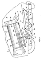
- FIG. 1 and 2 identify the general location of and depict one preferred embodiment of a transverse fan assembly 10 that has associated therewith a cut-off construction 11 according to the present invention arranged in operable combination with a typical, conventional, self-propelled agricultural combine harvester 12 of the axial-flow type wherein crop material is threshed and separated while it is advanced by and along a generally longitudinally arranged rotor.
- transverse fan assemblies of the present invention are not limited to use in such harvesters, but could equally as well be employed or utilized in or with other harvesters and equipment, including harvesters that employ dual rotor threshing systems and with equipment for other applications, or with other equipment or in other circumstances and situations, consistent with the principles and teachings expounded.
- the self-propelled combine harvester 12 is operatively powered by an engine (not shown) suitably housed within a body 14 of the combine harvester, which body 14 includes a cab 15 for a user, to provide driving power for the harvester 12.
- an engine suitably housed within a body 14 of the combine harvester, which body 14 includes a cab 15 for a user, to provide driving power for the harvester 12.
- the transfer of rotation and power from the engine to various driven components of the combine is of a conventional nature and could include fixed or variable belt or chain drives which are not shown for purposes of clarity.
- combine harvester 12 At its front end, combine harvester 12 is provided with a conventional crop harvesting header 16.
- the choice of header does not limit or relate to the present invention.
- the crop harvesting header 16 cuts and directs crop material into a conventional threshing apparatus 18.
- the threshing apparatus 18 typically includes a rotor assembly 20, including a relatively large diameter rotor 22 that is mounted within a threshing cage 24. Disposed about the cage 24 is a simple system of concaves 26 and separating grates 28 which, through the action of the rotor 22 and centrifugal force, act to separate grain material from other crop residue that is too large to pass through the concaves 26 and grates 28, sometimes hereafter referred to as straw.
- the threshed grain material is delivered to a cleaning system 29 that typically includes a pair of vertically spaced apart cleaning sieves 30 and 32 while the straw is propelled rearwardly through the rotor assembly 20 where a conventional beater 40 acts upon the crop residue discharged from the rotor assembly 20.
- Beater 40 propels the crop residue from the rear of the rotor assembly 20 and throws it back for broad discharge from the rear end of the combine.
- auger 34 moves the threshed grain material to the cleaning sieves 30 and 32, which sieves form part of the cleaning system 29 and are mounted for oscillation to separate grain from other larger pieces of threshed crop material.
- the sieves 30 and 32 are vibrated or oscillated, the grain falls through the sieves 30 and 32 to an underlying clean grain pan 35 and into a clean grain trough or collector 36.
- An auger 38 directs the grain from the clean grain trough 36 into a hopper or grain bin (not shown) often housed generally directly behind the cab 15 ( Fig. 1 ) within combine harvester body 14.
- the threshed grain material that is too large to fall through the sieves 30 and 32 forms a relatively large crop mat or veil extending across substantially the entire sieve construction, as fan assembly 10 provides air that is blown upwardly and rearwardly, as denoted by arrows A, through sieves 30 and 32.
- Such air flow acts to blow lighter, non-grain elements, sometimes referred to as chaff, away from the crop mat remaining on the sieves 30 and 32 towards the rear of the harvester, where such chaff is handled in conventional and well-known manners.
- tailings The larger and heavier threshed crop material, sometimes referred to as tailings, that remains on the sieves 30 and 32 as they continue to vibrate or oscillate is caused to pass over the ends of the sieves 30 and 32 to fall to an underlying tailings pan and into a tailings trough or collector 37.
- An auger 39 directs the tailings from the tailings trough to a tailings return conveyor system (not shown) that is operable to carry the tailings upwardly, back to the cleaning or separating systems of the combine harvester 12, for reprocessing, which may include further threshing of such tailings.
- Figs. 2-9 depict, in greater detail, a fan assembly 10, and components thereof, constructed to include a cut-off construction 11 in accordance with the present invention, with Fig. 2 depicting in greater detail such fan assembly 10 in combination with the cleaning sieves 30, 32, towards which sieves the air outflow from fan assembly 10 is directed.
- the fan assembly 10 comprises an elongated transverse or cross-flow fan 42 within an air plenum 44, with fan 42 extending generally transversely across a great extent, preferably substantially the entire width, of the combine harvester 12. More specifically, as shown in Fig. 2 , fan 42 is generally transversely mounted on the combine harvester 12 beneath the threshing apparatus 18 and preferably forward of the cleaning sieves 30, 32.
- fan 42 sometimes referred to as a fan rotor, includes a central and preferably elongated hub or axle 46 defining an elongated axis of a rotation 48 for the fan, a plurality of closely spaced fan blades 50 generally extending adjacent to and along axle 46, in an axially aligned configuration, and projecting outwardly in a circumferential array or pattern about the axis of rotation 48, to define an open center for the fan 42, and a plurality of fan blade mounting disks 52, spaced and aligned along axle 46, to which the fan blades 50 are mounted.
- fan embodiments that differ in various regards from fan 42, including by having fan blades that are disposed to wrap around the axle instead of extending in an axially aligned configuration, can also be conveniently utilized in transverse fan assemblies such as fan assembly 10, and cut-off constructions according to the present invention can be readily employed therewith, as will be further addressed hereinafter.
- each fan blade 50 is typically formed from a material such as sheet metal and is connected or mounted to the fan blade mounting disks 52.
- Each fan blade mounting disk 52 is a disk-shaped member that is connected to and extends generally radially outward from the axle 46 for driving the fan blades 50 mounted thereto.
- Such mounting disks 52 are preferably of substantially uniform diameter and, while shown in the noted figures as having a generally round geometric configuration, could take any suitable shape, such as, for example, spoke-shaped, star-shaped, and the like.
- At least a pair of fan blade mounting disks 52 are arranged toward opposite ends of the fan 42, but, since the length or expanse of the transverse fan 42 across air plenum 44 is functionally unlimited, additional disks 52 may be provided along the expanse of the fan 42 to counteract centrifugal forces acting on the blades 50 during operation of the fan assembly 10.
- Air plenum 44 which is preferably fabricated from an air impervious material, and as is better shown in Figs. 2 , 3 , 5 , and 7 , extends generally cross-wise across the combine harvester 12 and envelops a significant portion of fan 42 therewithin. As better shown in Fig. 5 , in the embodiment depicted therein, air plenum 44 extends along substantially and somewhat beyond the entire expanse of the fan 42, which is generally disposed within air plenum 44 extending generally transversely to the forward direction of travel of combine harvester 12.
- Axle 46 of fan 42 is typically supported and rotatably mounted in bearing blocks 58 and 60 secured at opposite sides of the air plenum 44, although it will be understood that various other constructions could be equally as well utilized to provide such support and that various constructions and systems of known design and operation can be readily employed to effect rotation of the fan 42 about its axis of rotation 48.
- air plenum 44 when viewed from the left side of the harvester 12, as best shown in Figs. 2 , 3 , and 6 , has a cross-sectional scroll-like configuration, with an air inlet 64 ( Fig. 3 ), sometimes hereinafter referred to as air inlet opening 64, an air outlet 66, sometimes hereinafter referred to as air outlet opening 66, and an internal chamber 68 in which fan 42 is mounted.
- air plenum 44 includes a continuous lower wall 70 that has an upstream curvilinear face 72 and a downstream curvilinear face 74, an upper air directing construction, such as baffle 76, and side walls 83, which side walls are better shown in Fig. 5 .
- Lower wall 70 wraps about the forward portion of fan 42, from air inlet opening 64 at the leading edge 65 of such lower wall 70, and extends generally rearwardly to air outlet opening 66.
- the upstream curvilinear face 72 of lower wall 70 is disposed closely adjacent the outer periphery of fan 42 to form an air inlet entryway 67 at and adjacent to the leading edge 65, and the downstream curvilinear face 74 extends rearwardly and upwardly, at an increasing distance from the fan 42, toward the sieves 30, 32 for directing air drawn into the fan 42 from air inlet 64 through air inlet entryway 67 rearwardly through internal chamber 68 towards air outlet opening 66 for discharge therethrough.
- Baffle 76 generally extends between cut-off construction 11, which is shown disposed at the forward or inner end portion of such baffle 76 generally proximate to the rearmost outer periphery of fan 42 at forward position FP ( Fig. 6 ), to a rear or outer end portion at air outlet 66.
- baffle 76, along with cut-off construction 11, serves to separate air inlet 64 from air outlet 66 and to direct the air flow from fan 42 towards air outlet 66.
- baffle 76 which forms a portion of the upper wall 77 for the output throat 79 of air plenum 44 from the downstream side of fan 42 to air outlet 66, is preferably generally smooth and devoid of projections and recesses that might interrupt the air flow therealong or result in the generation of undesirable vortices or other anomalies or disruptions in such air flow.
- air inlet entryway 67 in an air flow pathway from air inlet 64, which air inlet 64 typically extends across the top side of the fan 42 and is bounded rearwardly by cut-off 11 and baffle 76.
- the air so drawn into air plenum 44 by the rotation of fan 42 will be moved by operation of fan 42 through the output throat 79 in air plenum 44 towards air outlet 66 to be forcibly discharged through air outlet 66, as shown by arrows A.
- fan blades 50 and the fan blade mounting disks 52 of fan 42 are so designed that the fan blades 50 can be complementarily mounted and releasably secured to fan blade mounting disks 52, each of which fan blade mounting disks 52 is preferably of molded construction of metal or plastics material.
- fan blade mounting disk 52 includes a plurality of arcuately shaped axially facing fan blade mounting grooves 85 therein at angularly spaced locations about axis 48.
- Each mounting groove 85 is adapted for receiving therein a fan blade 50 of arcuate cross-section and includes a detent tab 87 that is insertable into a hole (not shown) in a fan blade 50 for retaining such fan blade 50 in such mounting groove 85, as better shown in Fig. 8 .
- Fig. 8 also illustrates certain spatial relationships for the fan 42 and its components, as well as the cut-off construction 11, that have been found to be beneficial, particularly relative to the configuration of the fan blades 50.
- fan blades 50 are shown having inner and outer ends 89 and 91 and generally extending radially about axis 48 of fan 42 within complementary mounting grooves 85 into which the fan blades 50 are releasably secured.
- the fan blades 50 will have a height or side-to-side width W ( Fig. 8 ) as measured between inner and outer ends 89 and 91 thereof of between about 5.8 to 6.1 cm (2.3 to 2.4 inches) and a radius of curvature between about 5.1 and 5.3 cm (2.0 and 2.1 inches).
- W height or side-to-side width
- the mounting grooves 85 are preferably configured and disposed in and about the fan blade mounting disks 52 such that, when a fan blade 50 is mounted within a plurality of mounting disks 52 that have been spaced and aligned along axle 46 of fan 42 so that the fan blade 50 is in a generally axially alignment with axis 48, inner end 89 of such fan blade 50 will be so oriented that a line tangent to the inner end 89 of fan blade 50 will pass through axis 48 of the fan, with such tangent line being designated as line FI, as a consequence of which, for the dimensions set forth hereinabove, as better shown in Fig. 8 , an angle ⁇ equal to about 28° will be formed between blade tip tangent line T1 and fan periphery tangent line T2, which angle ⁇ is defined to be the cut-off inclination angle for the present invention.
- the fan blade mounting disk 52 of Figs. 6-8 which is a representative exemplary embodiment of the fan blade mounting disks that may be employed in the fan 42 of Figs. 4 and 5 , is shown, especially in Figs. 7 and 8 , to have fan blades 50 mounted in alternating ones of the mounting grooves 85, thus resulting in twenty fan blades 50 generally axially aligned about axis 46 and radially spaced from one another by an angle ⁇ equal to approximately 18°.
- the outer ends 91 of adjacent mounted fan blades are thus preferably spaced from one another by about 5.8 to 6.1 cm (2.3 to 2.4 inches), as denoted by distance G in Fig. 8
- the inner ends 89 of such fan blades 50L and 50T are thus preferably spaced from one another by about 4.1 to 4.3 cm (1.6 to 1.7 inches), as designated by distance H in Fig. 8 .
- cut-off construction 11 is shown to be a body construction 300 that extends generally across the air plenum 44 and includes first and second plate-like body portions 302 and 304 that are positioned laterally to one another along the top of the output throat 77 of the air plenum, which body portions 302 and 304 each have respective generally planar inner surfaces 306 and 308 on one side thereof facing the output throat 77.
- First body portion 302 extends generally across the air plenum 44 along forward position FP with, as better shown in Fig. 8 , the generally planar inner surface 306 thereof projecting laterally from position FP and extending therefrom along blade tip tangent line T1, as the fan blade labeled 50T rotates past such forward position FP.
- the angle formed between blade tip tangent line T1 and fan periphery tangent line T2 is the cut-off inclination angle ⁇ which, in such embodiment, is approximately 28°.
- the generally planar inner surface 306 of such first body portion 302 projects laterally from the forward position FP in the air plenum 44 at cut-off inclination angle ⁇ and extends generally along or parallel to blade tip tangent line T1 until it intersects the generally planar inner surface 308 of the second body portion 304 at a juncture J therebetween to form juncture angle ⁇ between such planar inner surfaces 306 and 308.
- the generally planar inner surface 308 of the second body portion 304 projects laterally from such juncture J and extends towards the air outlet along a projection K that extends generally from such juncture J through the output throat 77 towards the air outlet 66 until the inner surface 308 meets and joins the baffle 76 in a generally smooth transition, as better shown in Figs. 3 and 6 .
- forward position FP is shown in Figs. 7 and 8 to be located near the outer periphery of fan 42 and slightly above centerline CL through fan 42. Although such positioning is favored, forward position FP can, if desired, be located at higher positions above centerline CL and rotated forwardly of the rearmost fan periphery tangent line TR near the outer periphery of the fan, although, as previously indicated, in such event it is then preferable that the angle between the then-forwardly tilted blade tip tangent line T2 and the rearmost fan periphery tangent line TR, defined to be subtended angle ⁇ , fall within a range 0° ⁇ . Often, as the subtended angle ⁇ increases in value, the juncture angle ⁇ will tend to decrease so that the projection of inner surface 308 will extend through output throat 79 towards the air outlet 66.
- Such cut-off construction configuration introduces into the upper wall 77 for the output throat 79, which wall 77 is formed by cut-off construction 11 and the baffle 76, a concavity or recess near the outer periphery of the fan, which concavity and its configuration, especially due to the position of the inner surface 306 of first body portion 302 at cut-off inclination angle ⁇ , effects a shift of the steering vortex of the fan in such a way to permit increased air flow volume at lower rotational fan speeds.
- the generally planar inner surface 306 of first body portion 302 of cut-off construction 11 preferably extends a distance L of approximately 1,9 cm (0.75 in.) to intersect the generally planar inner surface 308 of second body portion 304 at juncture J.
- juncture J lies within approximately the central third of the distance G between the outer tips of the adjacent fan blades 50L and 50T, as is preferred, and the juncture angle ⁇ formed by the intersection of inner surfaces 306 and 308 at juncture J is about 135°.
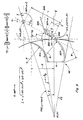
- Fig. 9 is an illustration, corresponding generally to Fig. 8 , further illustrating various of the parameters and relationships between the fan 42, its fan blades 50, and the cut-off construction 11, with various of the depicted components and features labeled in accordance with the discussions hereinabove.
- inner surface 306 of first body portion is shown extending outwardly or laterally from the fan 42 from a forward position FP closely adjacent to the outer periphery of fan 42 at a cut-off inclination angle ⁇ from the outer periphery of fan 42, as defined by a blade tip tangent line T1 and a fan periphery tangent line T2, with fan periphery tangent line T2 in such figure being coincident with the rearmost fan periphery tangent line FR and with forward position FP being located near and slightly above centerline CL.
- Cartesian coordinates of various points on such figure are set forth, based upon a coordinate system in which the axis 48 of the fan 42 is at coordinate (0,0), with the x-axis lying along centerline CL such that the outer tip 91 of trailing fan blade 50T is at about coordinate (r,0), where r is the radius of the fan 42.
- angles ⁇ and ⁇ and the preferred maximum length L of the inner surface 306 of first body portion 302 may be determined or established for fans and fan blades of various dimensions and configurations, and also how various parameters of the fan, the fan blades, and the cut-off construction of the present invention interrelate. It should be appreciated that, in accordance therewith, those skilled in the art may re-orient and/or reconfigure the cut-off construction in or with transverse fan assemblies whose components have dimensions that vary from the particular dimensions noted hereinabove and relative to which the preferred embodiment of the cut-off construction has been described and discussed.
- a change in the radius of curvature R of the fan blades 50 may result in or require a change of the cut-off inclination angle ⁇ and of the preferred maximum length L of the inner surface 306 of first body portion 302, and might also affect the juncture angle ⁇ , particularly if the radial tangent at the inner end of the fan blades 50 is maintained aligned with a radian of the fan 42.
- a fan were to have a diameter D different from that of fan 42, corresponding changes occasioned thereby might well be required for a cut-off construction according to the present invention.
- cut-off construction 11 has been described and discussed primarily with respect to its utilization with fans that have generally axially aligned fan blades. It should be understood and appreciated, however, that the utilization of cut-off construction 11 is not restricted to fans with axially aligned fan blades.
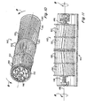
- Figs. 10 and 11 which correspond generally and respectively to Figs. 4 and 5 , depict a fan 142 of a somewhat different construction than fan 42, which fan 142 may be employed in the transverse fan assembly 10 in place of fan 42, and with which the cut-off construction 11 embodiment, already discussed and described hereinbefore, may also be utilized.
- Fan 142 includes fan blades 150 disposed to partially wrap around the axle 146 and axis 148 of fan 142 so as to define a chevron blade pattern, with the leading portions of the fan blades 150 being generally centered along the length of the fan 142 as fan 142 and its axle 146 are rotated forwardly about axis 148.
- fans with such chevron blade patterns are considered to offer certain advantages over fans that, instead, utilize axially aligned fan blades, such as fan 42, including for the purpose of reducing fan noise.
- the fan 142 is typical of a fan that employs non-axially aligned fan blades.
- the fan 142 of Figs. 10 and 11 includes a plurality of fan blade lengths extending along the axle 146 between the opposite ends of the fan 142, each of which fan blade lengths includes a pair of fan blades 150 disposed generally end-to-end to one another, with each of such fan blades 150 extending from an opposite end of the fan 142 to approximately halfway along the length of the fan to meet near the center of the length of the fan 142.
- Such fan blades 150, and the fan blade lengths formed thereby are arranged in spaced alignment relative to one other as they wrap about the axis 148 of fan 142 such that the center portion of each fan blade length is offset in circumferential relation relative to the opposite end thereof.
- each fan blade 150 of each fan blade length thus slant or angle from the opposite ends of the fan 142 toward a peripheral center portion of the fan 142 so that each fan blade length, when viewed looking across the expanse of the fan 142, as in Fig. 11 , has a chevron-like configuration between opposite ends thereof, with the chevron "pointing" in the direction of forward fan rotation when the fan is operating, shown as arrows B in Figs. 10 and 11 .
- the degree of slanting, or angle, of the fan blades 150 that may be used for noise reduction is not without limits, however.
- the blade angle is increased from zero with respect to the axis of rotation 148, zero angle being an axially straight blade, air flow outwardly from the fan is initially increased, air flow uniformity is improved, and noise is reduced.
- the fan blade angle is increased further, air flow in the axial direction of the fan increases, lessening the air flowing tangentially from the fan blades which tends to negatively affect air flow rate and uniformity, and to increase noise. Consequently, the amount or degree of slanting of the fan blades is typically chosen by manufacturers and users to be appropriate for any particular fan based upon the intended use of such fan and the effects desired as well as the constructional details of the fan assembly.
- fans with appropriately slanted fan blades can be readily utilized with a cut-off construction according to the present invention, such as cut-off construction 11, including by substituting fan 142 in place of fan 42 in the transverse fan assembly 10 of Figs. 1-3 and 7-8 .
- cut-off construction 11 including by substituting fan 142 in place of fan 42 in the transverse fan assembly 10 of Figs. 1-3 and 7-8 .
- the advantages attendant to the use of both a chevron-bladed fan and the cut-off construction of the present invention may be realized in the resulting transverse fan assembly.
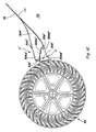
- Fig. 12 which corresponds generally to Fig. 8 , depicts an exemplary alternative cut-off construction 11' such as might also be utilized with a fan that has axially aligned fan blades, such as fan 42, to achieve results similar to those achieved by the use of cut-off construction 11 with fan 142.
- Cut-off construction 11' is a body construction 300' that includes first and second body portions 302' and 304' positioned laterally to one another and extending generally across the air plenum near the outer periphery of fan 42 at its downstream side.
- the respective generally planar inner surfaces 306' and 308' of such first and second body portions 302' and 304' have respective pairs of opposed inner surface end portions 306A', 306B' and 308A', 308B' that are angularly inclined from their opposite ends at opposite sides of the air plenum towards the center of such air plenum so that such inner surface 306', including inner surface end portions 306A' and 306B', and inner surface 308', including inner surface end portions 308A' and 308B', will, if viewed in cross-section looking towards the air outlet of the air plenum from near the center of the expanse of the fan, thus generally appear to have a tented or inverted "V" shape across the output throat of the air plenum.
- opposite inner surface end portions 306A' and 306B' of inner surface 306' of first body portion 302 extend angularly from near the outer periphery of fan 42 and generally rearwardly in a plane generally perpendicular to the expanse of the fan 42 from generally adjacent the outer periphery of fan 42 at a cut-off inclination angle ⁇ to a juncture with respective inner surface opposite end portions 308A' and 308B' of inner surface 308' of second body portion 304'.
- the inner surface end portion 306A' or 306B' of first body portion 302' of cut-off construction 11' intersects a respective inner surface end portion 308A' or 308B' of inner surface 308' of second body portion 304' to define a juncture angle ⁇ therebetween, with end portion 308A' or 308B' extending from such juncture to join, in a generally smooth transition, baffle 76.
- the juncture angle ⁇ formed by the intersection of the inner surfaces 306' and 308' of the first and second body portions 302' and 304' is not uniform along the cross-plenum expanse of the cut-off construction 11', but varies, in Fig. 12 , from a larger angle of approximately 135° in a plane near the opposite ends of the fan 42 to a smaller angle of approximately 118° in a plane near the center of the fan 42.
- the inner surfaces 306' and 308' of the first and second body portions 302' and 304' of cut-off construction 11' appear, in any given plane perpendicular to the fan 42 and extending through the output throat 77 of the air plenum 44, to form an inverted "V" shape similar to the inverted "V" shape discussed hereinbefore with respect to the cut-off construction 11 for the fan with axially aligned fan blades.
- first and second body portions thereof have been depicted as plate-like elements, with upper surfaces generally parallel to the inner surfaces which face the output throat 77 of the air plenum.
- first and second body portions could assume various other shapes and configurations, especially in their upper body shapes, consistent with the present invention and without departing from the scope of the invention as defined by the claims, and that the depiction of the first and second body portions as plate-like elements is not intended to be limiting in any way, except as may be required by the claims which follow.
- cut-off construction of the present invention has been described and discussed herein primarily with respect to its inclusion in or with transverse fan assemblies employed within agricultural combines, it should be understood and appreciated that its use is not limited to such agricultural combines or related equipment, but may more generally be employed with transverse assemblies of various types and for various uses, all within the scope of the present invention and for the intended purposes.
Landscapes
- Engineering & Computer Science (AREA)
- Mechanical Engineering (AREA)
- General Engineering & Computer Science (AREA)
- Life Sciences & Earth Sciences (AREA)
- Environmental Sciences (AREA)
- Structures Of Non-Positive Displacement Pumps (AREA)
Applications Claiming Priority (1)
| Application Number | Priority Date | Filing Date | Title |
|---|---|---|---|
| US12/321,076 US8052374B2 (en) | 2009-01-15 | 2009-01-15 | Cut-off construction for transverse fan assemblies that have elongated fan blades of arcuate cross-section |
Publications (3)
| Publication Number | Publication Date |
|---|---|
| EP2208412A2 true EP2208412A2 (fr) | 2010-07-21 |
| EP2208412A3 EP2208412A3 (fr) | 2017-08-16 |
| EP2208412B1 EP2208412B1 (fr) | 2019-05-22 |
Family
ID=42109807
Family Applications (1)
| Application Number | Title | Priority Date | Filing Date |
|---|---|---|---|
| EP10150669.9A Active EP2208412B1 (fr) | 2009-01-15 | 2010-01-13 | Construction de coupure améliorée pour ensemble de ventilateur transversal |
Country Status (2)
| Country | Link |
|---|---|
| US (1) | US8052374B2 (fr) |
| EP (1) | EP2208412B1 (fr) |
Cited By (1)
| Publication number | Priority date | Publication date | Assignee | Title |
|---|---|---|---|---|
| US10687470B2 (en) | 2015-09-09 | 2020-06-23 | Agco International Gmbh | Grain cleaning system in a combine harvester |
Families Citing this family (18)
| Publication number | Priority date | Publication date | Assignee | Title |
|---|---|---|---|---|
| US8801512B2 (en) * | 2011-12-19 | 2014-08-12 | Agco Corporation | Method for measuring air efficiency and efficacy in a combine harvester |
| US8608534B1 (en) * | 2012-09-25 | 2013-12-17 | Agco Corporation | Rolled secondary cut off in air distribution system of a combine harvester |
| US9033779B2 (en) * | 2012-11-29 | 2015-05-19 | Cnh Industrial America Llc | Air diverter for a cleaning system of a combine harvester |
| US8821229B2 (en) | 2012-12-06 | 2014-09-02 | Cnh Industrial America Llc | Grain cleaning system for an agricultural combine |
| US10054125B2 (en) * | 2014-03-25 | 2018-08-21 | Kyocera Document Solutions Inc. | Cross-flow fan, electronic device, and impeller |
| CN205779896U (zh) * | 2015-10-30 | 2016-12-07 | 广东科利亚现代农业装备有限公司 | 一种甘蔗收割机的下风机风轮 |
| CN106385999B (zh) * | 2016-08-29 | 2019-06-28 | 江苏大学 | 切流与纵轴流装置脱粒分离负荷的自适应调控系统 |
| US10694678B2 (en) * | 2018-04-29 | 2020-06-30 | Deere & Company | Combine harvester fan housing assembly |
| EP3566568B1 (fr) * | 2018-05-09 | 2022-08-10 | CNH Industrial Belgium N.V. | Déflecteur d'air pour ensemble de nettoyage de moissonneuse combinée |
| FR3093763B1 (fr) * | 2019-03-15 | 2021-04-02 | Valeo Systemes Thermiques | Module de refroidissement à zone sacrificielle pour véhicule automobile électrique |
| FR3093760B1 (fr) * | 2019-03-15 | 2021-04-02 | Valeo Systemes Thermiques | Module de refroidissement pour véhicule automobile électrique à turbomachine tangentielle |
| US11395984B2 (en) * | 2019-05-24 | 2022-07-26 | Flory Industries | Dust control system and related methods |
| CN114413296A (zh) * | 2020-10-28 | 2022-04-29 | 佛山市顺德区美的洗涤电器制造有限公司 | 一种烟机 |
| WO2022159320A1 (fr) * | 2021-01-22 | 2022-07-28 | Cnh Industrial America Llc | Configuration de parafouille secondaire pour ventilateur à flux transversal |
| US20220279726A1 (en) * | 2021-03-04 | 2022-09-08 | Cnh Industrial America Llc | Inlet cover for a cross flow fan |
| FR3121177B1 (fr) * | 2021-03-25 | 2024-07-12 | Valeo Systemes Thermiques | Module de refroidissement pour véhicule automobile électrique ou hybride à turbomachine tangentielle |
| CN115653911B (zh) * | 2022-11-02 | 2025-08-08 | 安徽金马电气科技有限公司 | 一种干式变压器及电力设备 |
| US12453310B2 (en) | 2023-02-01 | 2025-10-28 | Cnh Industrial America Llc | Hydraulic cleaning fan drive for combine harvester utilizing swing-arm actuated pump |
Citations (1)
| Publication number | Priority date | Publication date | Assignee | Title |
|---|---|---|---|---|
| US5599162A (en) | 1995-08-09 | 1997-02-04 | Case Corporation | Transverse blower fan assembly |
Family Cites Families (22)
| Publication number | Priority date | Publication date | Assignee | Title |
|---|---|---|---|---|
| US997127A (en) * | 1909-08-13 | 1911-07-04 | Joseph F Hanrahan | Fan. |
| US1050540A (en) * | 1911-05-10 | 1913-01-14 | Fredrick A Hohman | Threshing-machine. |
| US3415443A (en) * | 1966-05-23 | 1968-12-10 | Torrington Mfg Co | Transverse flow blower with high velocity discharge |
| GB1131689A (en) * | 1966-08-20 | 1968-10-23 | Heidolph Elektro Kg | Blowers |
| US3533413A (en) * | 1967-06-16 | 1970-10-13 | Case Co J I | Cleaning unit for combine |
| US3469773A (en) * | 1968-07-12 | 1969-09-30 | Int Harvester Co | Fan for combine |
| US3664349A (en) * | 1969-12-19 | 1972-05-23 | Univ Iowa State Res Found | Combine cleaning blower |
| US3833006A (en) * | 1972-12-01 | 1974-09-03 | Allis Chalmers | Duct damper for transverse fan |
| US4078870A (en) * | 1976-06-16 | 1978-03-14 | International Standard Electric Corporation | Tangential blower |
| GB2055969B (en) * | 1979-07-19 | 1983-11-16 | Sgm Co Inc | Low noise centrifugal blower |
| DE3016438C2 (de) * | 1980-04-29 | 1985-12-19 | Standard Elektrik Lorenz Ag, 7000 Stuttgart | Querstromlüfter |
| DE3048571A1 (de) | 1980-12-22 | 1982-07-22 | Ltg Lufttechnische Gmbh, 7000 Stuttgart | Querstromventilator |
| US5197850A (en) * | 1987-01-30 | 1993-03-30 | Sharp Kabushiki Kaisha | Cross flow fan system |
| US4906219A (en) * | 1988-08-15 | 1990-03-06 | J. I. Case Company | Cleaning system for a combine |
| KR930006876B1 (ko) * | 1989-06-23 | 1993-07-24 | 가부시끼 가이샤 히다찌세이사꾸쇼 | 관류팬을 사용한 송풍장치 및 공기조화기 |
| US5165855A (en) * | 1991-06-25 | 1992-11-24 | Case Corporation | Transverse blower fan and method of assembly |
| JPH05126088A (ja) | 1991-10-31 | 1993-05-21 | Toshiba Lighting & Technol Corp | 横流送風機およびその製造方法 |
| DE4138530A1 (de) * | 1991-11-23 | 1993-05-27 | Kloeckner Humboldt Deutz Ag | Reinigungsvorrichtung fuer maehdrescher |
| US5449271A (en) * | 1994-12-27 | 1995-09-12 | Carrier Corporation | Transverse fan with randomly varying I-shaped tongue |
| US5868551A (en) * | 1997-05-02 | 1999-02-09 | American Standard Inc. | Tangential fan cutoff |
| US7144219B2 (en) * | 2003-06-13 | 2006-12-05 | American Standard International Inc. | Cutoff for fan or blower |
| US20050013685A1 (en) * | 2003-07-18 | 2005-01-20 | Ricketts Jonathan E. | Cross flow fan |
-
2009
- 2009-01-15 US US12/321,076 patent/US8052374B2/en active Active
-
2010
- 2010-01-13 EP EP10150669.9A patent/EP2208412B1/fr active Active
Patent Citations (1)
| Publication number | Priority date | Publication date | Assignee | Title |
|---|---|---|---|---|
| US5599162A (en) | 1995-08-09 | 1997-02-04 | Case Corporation | Transverse blower fan assembly |
Cited By (1)
| Publication number | Priority date | Publication date | Assignee | Title |
|---|---|---|---|---|
| US10687470B2 (en) | 2015-09-09 | 2020-06-23 | Agco International Gmbh | Grain cleaning system in a combine harvester |
Also Published As
| Publication number | Publication date |
|---|---|
| EP2208412B1 (fr) | 2019-05-22 |
| US20100178171A1 (en) | 2010-07-15 |
| EP2208412A3 (fr) | 2017-08-16 |
| US8052374B2 (en) | 2011-11-08 |
Similar Documents
| Publication | Publication Date | Title |
|---|---|---|
| EP2208412B1 (fr) | Construction de coupure améliorée pour ensemble de ventilateur transversal | |
| US8221064B2 (en) | Transverse fan assembly having a supplementary air feed inlet for infill of air flow deficiencies to effect a desired output air flow pattern, and method of use thereof | |
| US3848609A (en) | Axial flow type harvesting machines | |
| EP3466243B1 (fr) | Boîtier de ventilateur segmenté pour système de nettoyage de moissonneuse-batteuse | |
| US7104883B2 (en) | Straw chopper blade | |
| PL108184B1 (pl) | Kombajn zbozowy o przeplywie osiowym axial flow combine-harvester | |
| US5599162A (en) | Transverse blower fan assembly | |
| EP1872647B1 (fr) | Entrée chevron pour ventilateur à courants croisés | |
| RU2490862C2 (ru) | Зерноуборочный комбайн с очистным вентилятором | |
| US8147303B2 (en) | Harvested crop chopper remains and distribution arrangement for a combine | |
| EP1872646B1 (fr) | Entrée rotative pour ventilateur à courants croisés | |
| US11812701B2 (en) | Tangential feeding to a threshing rotor | |
| US6974384B2 (en) | Tailings conveyor with rotary impellers disposed and rotatable at progressively faster speeds for threshing and conveying tailings through the conveyor and method of operation of the same | |
| US6908378B2 (en) | Threshing rotor inlet flight extension | |
| USRE31860E (en) | Harvesting machines | |
| US6991537B2 (en) | Deflector for a discharge outlet of a tailings conveyor of an agricultural combine | |
| CN110769683A (zh) | 联合收割机 | |
| US6976914B2 (en) | Impeller with swept back blades for a tailings conveyor of an agricultural combine | |
| CN107846844B (zh) | 农业收割机的螺旋输送器组件 | |
| JP2019004738A (ja) | コンバイン | |
| JPH0437406Y2 (fr) | ||
| JPS6137242Y2 (fr) | ||
| JP2019004740A (ja) | コンバイン |
Legal Events
| Date | Code | Title | Description |
|---|---|---|---|
| PUAI | Public reference made under article 153(3) epc to a published international application that has entered the european phase |
Free format text: ORIGINAL CODE: 0009012 |
|
| AK | Designated contracting states |
Kind code of ref document: A2 Designated state(s): AT BE BG CH CY CZ DE DK EE ES FI FR GB GR HR HU IE IS IT LI LT LU LV MC MK MT NL NO PL PT RO SE SI SK SM TR |
|
| AX | Request for extension of the european patent |
Extension state: AL BA RS |
|
| RAP1 | Party data changed (applicant data changed or rights of an application transferred) |
Owner name: CNH INDUSTRIAL BELGIUM NV |
|
| PUAL | Search report despatched |
Free format text: ORIGINAL CODE: 0009013 |
|
| AK | Designated contracting states |
Kind code of ref document: A3 Designated state(s): AT BE BG CH CY CZ DE DK EE ES FI FR GB GR HR HU IE IS IT LI LT LU LV MC MK MT NL NO PL PT RO SE SI SK SM TR |
|
| AX | Request for extension of the european patent |
Extension state: AL BA RS |
|
| RIC1 | Information provided on ipc code assigned before grant |
Ipc: F04D 17/04 20060101ALI20170710BHEP Ipc: A01F 12/44 20060101AFI20170710BHEP Ipc: F04D 29/28 20060101ALI20170710BHEP |
|
| STAA | Information on the status of an ep patent application or granted ep patent |
Free format text: STATUS: REQUEST FOR EXAMINATION WAS MADE |
|
| 17P | Request for examination filed |
Effective date: 20180216 |
|
| RBV | Designated contracting states (corrected) |
Designated state(s): AT BE BG CH CY CZ DE DK EE ES FI FR GB GR HR HU IE IS IT LI LT LU LV MC MK MT NL NO PL PT RO SE SI SK SM TR |
|
| GRAP | Despatch of communication of intention to grant a patent |
Free format text: ORIGINAL CODE: EPIDOSNIGR1 |
|
| STAA | Information on the status of an ep patent application or granted ep patent |
Free format text: STATUS: GRANT OF PATENT IS INTENDED |
|
| RIC1 | Information provided on ipc code assigned before grant |
Ipc: A01F 12/44 20060101AFI20181116BHEP Ipc: F04D 17/04 20060101ALI20181116BHEP Ipc: F04D 29/28 20060101ALI20181116BHEP |
|
| INTG | Intention to grant announced |
Effective date: 20181206 |
|
| GRAS | Grant fee paid |
Free format text: ORIGINAL CODE: EPIDOSNIGR3 |
|
| GRAA | (expected) grant |
Free format text: ORIGINAL CODE: 0009210 |
|
| STAA | Information on the status of an ep patent application or granted ep patent |
Free format text: STATUS: THE PATENT HAS BEEN GRANTED |
|
| AK | Designated contracting states |
Kind code of ref document: B1 Designated state(s): AT BE BG CH CY CZ DE DK EE ES FI FR GB GR HR HU IE IS IT LI LT LU LV MC MK MT NL NO PL PT RO SE SI SK SM TR |
|
| REG | Reference to a national code |
Ref country code: GB Ref legal event code: FG4D |
|
| REG | Reference to a national code |
Ref country code: CH Ref legal event code: EP |
|
| REG | Reference to a national code |
Ref country code: IE Ref legal event code: FG4D |
|
| REG | Reference to a national code |
Ref country code: DE Ref legal event code: R096 Ref document number: 602010059006 Country of ref document: DE |
|
| REG | Reference to a national code |
Ref country code: AT Ref legal event code: REF Ref document number: 1134943 Country of ref document: AT Kind code of ref document: T Effective date: 20190615 |
|
| REG | Reference to a national code |
Ref country code: NL Ref legal event code: MP Effective date: 20190522 |
|
| REG | Reference to a national code |
Ref country code: LT Ref legal event code: MG4D |
|
| PG25 | Lapsed in a contracting state [announced via postgrant information from national office to epo] |
Ref country code: ES Free format text: LAPSE BECAUSE OF FAILURE TO SUBMIT A TRANSLATION OF THE DESCRIPTION OR TO PAY THE FEE WITHIN THE PRESCRIBED TIME-LIMIT Effective date: 20190522 Ref country code: LT Free format text: LAPSE BECAUSE OF FAILURE TO SUBMIT A TRANSLATION OF THE DESCRIPTION OR TO PAY THE FEE WITHIN THE PRESCRIBED TIME-LIMIT Effective date: 20190522 Ref country code: HR Free format text: LAPSE BECAUSE OF FAILURE TO SUBMIT A TRANSLATION OF THE DESCRIPTION OR TO PAY THE FEE WITHIN THE PRESCRIBED TIME-LIMIT Effective date: 20190522 Ref country code: NL Free format text: LAPSE BECAUSE OF FAILURE TO SUBMIT A TRANSLATION OF THE DESCRIPTION OR TO PAY THE FEE WITHIN THE PRESCRIBED TIME-LIMIT Effective date: 20190522 Ref country code: PT Free format text: LAPSE BECAUSE OF FAILURE TO SUBMIT A TRANSLATION OF THE DESCRIPTION OR TO PAY THE FEE WITHIN THE PRESCRIBED TIME-LIMIT Effective date: 20190922 Ref country code: SE Free format text: LAPSE BECAUSE OF FAILURE TO SUBMIT A TRANSLATION OF THE DESCRIPTION OR TO PAY THE FEE WITHIN THE PRESCRIBED TIME-LIMIT Effective date: 20190522 Ref country code: NO Free format text: LAPSE BECAUSE OF FAILURE TO SUBMIT A TRANSLATION OF THE DESCRIPTION OR TO PAY THE FEE WITHIN THE PRESCRIBED TIME-LIMIT Effective date: 20190822 Ref country code: FI Free format text: LAPSE BECAUSE OF FAILURE TO SUBMIT A TRANSLATION OF THE DESCRIPTION OR TO PAY THE FEE WITHIN THE PRESCRIBED TIME-LIMIT Effective date: 20190522 |
|
| PG25 | Lapsed in a contracting state [announced via postgrant information from national office to epo] |
Ref country code: LV Free format text: LAPSE BECAUSE OF FAILURE TO SUBMIT A TRANSLATION OF THE DESCRIPTION OR TO PAY THE FEE WITHIN THE PRESCRIBED TIME-LIMIT Effective date: 20190522 Ref country code: GR Free format text: LAPSE BECAUSE OF FAILURE TO SUBMIT A TRANSLATION OF THE DESCRIPTION OR TO PAY THE FEE WITHIN THE PRESCRIBED TIME-LIMIT Effective date: 20190823 Ref country code: BG Free format text: LAPSE BECAUSE OF FAILURE TO SUBMIT A TRANSLATION OF THE DESCRIPTION OR TO PAY THE FEE WITHIN THE PRESCRIBED TIME-LIMIT Effective date: 20190822 |
|
| REG | Reference to a national code |
Ref country code: AT Ref legal event code: MK05 Ref document number: 1134943 Country of ref document: AT Kind code of ref document: T Effective date: 20190522 |
|
| PG25 | Lapsed in a contracting state [announced via postgrant information from national office to epo] |
Ref country code: EE Free format text: LAPSE BECAUSE OF FAILURE TO SUBMIT A TRANSLATION OF THE DESCRIPTION OR TO PAY THE FEE WITHIN THE PRESCRIBED TIME-LIMIT Effective date: 20190522 Ref country code: AT Free format text: LAPSE BECAUSE OF FAILURE TO SUBMIT A TRANSLATION OF THE DESCRIPTION OR TO PAY THE FEE WITHIN THE PRESCRIBED TIME-LIMIT Effective date: 20190522 Ref country code: DK Free format text: LAPSE BECAUSE OF FAILURE TO SUBMIT A TRANSLATION OF THE DESCRIPTION OR TO PAY THE FEE WITHIN THE PRESCRIBED TIME-LIMIT Effective date: 20190522 Ref country code: CZ Free format text: LAPSE BECAUSE OF FAILURE TO SUBMIT A TRANSLATION OF THE DESCRIPTION OR TO PAY THE FEE WITHIN THE PRESCRIBED TIME-LIMIT Effective date: 20190522 Ref country code: RO Free format text: LAPSE BECAUSE OF FAILURE TO SUBMIT A TRANSLATION OF THE DESCRIPTION OR TO PAY THE FEE WITHIN THE PRESCRIBED TIME-LIMIT Effective date: 20190522 Ref country code: SK Free format text: LAPSE BECAUSE OF FAILURE TO SUBMIT A TRANSLATION OF THE DESCRIPTION OR TO PAY THE FEE WITHIN THE PRESCRIBED TIME-LIMIT Effective date: 20190522 |
|
| REG | Reference to a national code |
Ref country code: DE Ref legal event code: R097 Ref document number: 602010059006 Country of ref document: DE |
|
| PG25 | Lapsed in a contracting state [announced via postgrant information from national office to epo] |
Ref country code: SM Free format text: LAPSE BECAUSE OF FAILURE TO SUBMIT A TRANSLATION OF THE DESCRIPTION OR TO PAY THE FEE WITHIN THE PRESCRIBED TIME-LIMIT Effective date: 20190522 |
|
| PLBE | No opposition filed within time limit |
Free format text: ORIGINAL CODE: 0009261 |
|
| STAA | Information on the status of an ep patent application or granted ep patent |
Free format text: STATUS: NO OPPOSITION FILED WITHIN TIME LIMIT |
|
| PG25 | Lapsed in a contracting state [announced via postgrant information from national office to epo] |
Ref country code: TR Free format text: LAPSE BECAUSE OF FAILURE TO SUBMIT A TRANSLATION OF THE DESCRIPTION OR TO PAY THE FEE WITHIN THE PRESCRIBED TIME-LIMIT Effective date: 20190522 |
|
| 26N | No opposition filed |
Effective date: 20200225 |
|
| PG25 | Lapsed in a contracting state [announced via postgrant information from national office to epo] |
Ref country code: PL Free format text: LAPSE BECAUSE OF FAILURE TO SUBMIT A TRANSLATION OF THE DESCRIPTION OR TO PAY THE FEE WITHIN THE PRESCRIBED TIME-LIMIT Effective date: 20190522 |
|
| PGFP | Annual fee paid to national office [announced via postgrant information from national office to epo] |
Ref country code: GB Payment date: 20200128 Year of fee payment: 11 |
|
| PG25 | Lapsed in a contracting state [announced via postgrant information from national office to epo] |
Ref country code: SI Free format text: LAPSE BECAUSE OF FAILURE TO SUBMIT A TRANSLATION OF THE DESCRIPTION OR TO PAY THE FEE WITHIN THE PRESCRIBED TIME-LIMIT Effective date: 20190522 |
|
| PG25 | Lapsed in a contracting state [announced via postgrant information from national office to epo] |
Ref country code: MC Free format text: LAPSE BECAUSE OF FAILURE TO SUBMIT A TRANSLATION OF THE DESCRIPTION OR TO PAY THE FEE WITHIN THE PRESCRIBED TIME-LIMIT Effective date: 20190522 |
|
| REG | Reference to a national code |
Ref country code: CH Ref legal event code: PL |
|
| REG | Reference to a national code |
Ref country code: BE Ref legal event code: MM Effective date: 20200131 |
|
| PG25 | Lapsed in a contracting state [announced via postgrant information from national office to epo] |
Ref country code: LU Free format text: LAPSE BECAUSE OF NON-PAYMENT OF DUE FEES Effective date: 20200113 |
|
| PG25 | Lapsed in a contracting state [announced via postgrant information from national office to epo] |
Ref country code: BE Free format text: LAPSE BECAUSE OF NON-PAYMENT OF DUE FEES Effective date: 20200131 Ref country code: CH Free format text: LAPSE BECAUSE OF NON-PAYMENT OF DUE FEES Effective date: 20200131 Ref country code: LI Free format text: LAPSE BECAUSE OF NON-PAYMENT OF DUE FEES Effective date: 20200131 |
|
| REG | Reference to a national code |
Ref country code: DE Ref legal event code: R084 Ref document number: 602010059006 Country of ref document: DE |
|
| PG25 | Lapsed in a contracting state [announced via postgrant information from national office to epo] |
Ref country code: IE Free format text: LAPSE BECAUSE OF NON-PAYMENT OF DUE FEES Effective date: 20200113 |
|
| GBPC | Gb: european patent ceased through non-payment of renewal fee |
Effective date: 20210113 |
|
| PG25 | Lapsed in a contracting state [announced via postgrant information from national office to epo] |
Ref country code: GB Free format text: LAPSE BECAUSE OF NON-PAYMENT OF DUE FEES Effective date: 20210113 |
|
| PG25 | Lapsed in a contracting state [announced via postgrant information from national office to epo] |
Ref country code: MT Free format text: LAPSE BECAUSE OF FAILURE TO SUBMIT A TRANSLATION OF THE DESCRIPTION OR TO PAY THE FEE WITHIN THE PRESCRIBED TIME-LIMIT Effective date: 20190522 Ref country code: CY Free format text: LAPSE BECAUSE OF FAILURE TO SUBMIT A TRANSLATION OF THE DESCRIPTION OR TO PAY THE FEE WITHIN THE PRESCRIBED TIME-LIMIT Effective date: 20190522 |
|
| PG25 | Lapsed in a contracting state [announced via postgrant information from national office to epo] |
Ref country code: MK Free format text: LAPSE BECAUSE OF FAILURE TO SUBMIT A TRANSLATION OF THE DESCRIPTION OR TO PAY THE FEE WITHIN THE PRESCRIBED TIME-LIMIT Effective date: 20190522 Ref country code: IS Free format text: LAPSE BECAUSE OF FAILURE TO SUBMIT A TRANSLATION OF THE DESCRIPTION OR TO PAY THE FEE WITHIN THE PRESCRIBED TIME-LIMIT Effective date: 20190922 |
|
| PGFP | Annual fee paid to national office [announced via postgrant information from national office to epo] |
Ref country code: FR Payment date: 20230125 Year of fee payment: 14 |
|
| PGFP | Annual fee paid to national office [announced via postgrant information from national office to epo] |
Ref country code: IT Payment date: 20230110 Year of fee payment: 14 |
|
| PG25 | Lapsed in a contracting state [announced via postgrant information from national office to epo] |
Ref country code: FR Free format text: LAPSE BECAUSE OF NON-PAYMENT OF DUE FEES Effective date: 20240131 |
|
| PG25 | Lapsed in a contracting state [announced via postgrant information from national office to epo] |
Ref country code: FR Free format text: LAPSE BECAUSE OF NON-PAYMENT OF DUE FEES Effective date: 20240131 |
|
| PG25 | Lapsed in a contracting state [announced via postgrant information from national office to epo] |
Ref country code: IT Free format text: LAPSE BECAUSE OF NON-PAYMENT OF DUE FEES Effective date: 20240113 |
|
| PGFP | Annual fee paid to national office [announced via postgrant information from national office to epo] |
Ref country code: DE Payment date: 20260127 Year of fee payment: 17 |