EP2208433B1 - Appareil de coiffure - Google Patents
Appareil de coiffure Download PDFInfo
- Publication number
- EP2208433B1 EP2208433B1 EP10356005.8A EP10356005A EP2208433B1 EP 2208433 B1 EP2208433 B1 EP 2208433B1 EP 10356005 A EP10356005 A EP 10356005A EP 2208433 B1 EP2208433 B1 EP 2208433B1
- Authority
- EP
- European Patent Office
- Prior art keywords
- hair
- smoothing
- smoothing region
- complementary
- lock
- Prior art date
- Legal status (The legal status is an assumption and is not a legal conclusion. Google has not performed a legal analysis and makes no representation as to the accuracy of the status listed.)
- Active
Links
- 238000009499 grossing Methods 0.000 claims description 74
- 230000000295 complement effect Effects 0.000 claims description 27
- 238000010438 heat treatment Methods 0.000 claims description 10
- 230000001681 protective effect Effects 0.000 claims description 3
- 238000011144 upstream manufacturing Methods 0.000 claims description 2
- 230000000712 assembly Effects 0.000 claims 3
- 238000000429 assembly Methods 0.000 claims 3
- 230000000694 effects Effects 0.000 description 4
- 241001272996 Polyphylla fullo Species 0.000 description 3
- 210000004761 scalp Anatomy 0.000 description 3
- XEEYBQQBJWHFJM-UHFFFAOYSA-N Iron Chemical compound [Fe] XEEYBQQBJWHFJM-UHFFFAOYSA-N 0.000 description 2
- 239000000956 alloy Substances 0.000 description 2
- 229910045601 alloy Inorganic materials 0.000 description 2
- 238000003780 insertion Methods 0.000 description 2
- 230000037431 insertion Effects 0.000 description 2
- 238000000926 separation method Methods 0.000 description 2
- 238000007493 shaping process Methods 0.000 description 2
- RYGMFSIKBFXOCR-UHFFFAOYSA-N Copper Chemical compound [Cu] RYGMFSIKBFXOCR-UHFFFAOYSA-N 0.000 description 1
- 229910000831 Steel Inorganic materials 0.000 description 1
- 229910052782 aluminium Inorganic materials 0.000 description 1
- XAGFODPZIPBFFR-UHFFFAOYSA-N aluminium Chemical compound [Al] XAGFODPZIPBFFR-UHFFFAOYSA-N 0.000 description 1
- 230000006835 compression Effects 0.000 description 1
- 238000007906 compression Methods 0.000 description 1
- 239000004020 conductor Substances 0.000 description 1
- 229910052802 copper Inorganic materials 0.000 description 1
- 239000010949 copper Substances 0.000 description 1
- 238000006073 displacement reaction Methods 0.000 description 1
- 210000003128 head Anatomy 0.000 description 1
- 238000002347 injection Methods 0.000 description 1
- 239000007924 injection Substances 0.000 description 1
- 229910052742 iron Inorganic materials 0.000 description 1
- 239000000463 material Substances 0.000 description 1
- 239000007769 metal material Substances 0.000 description 1
- 238000000034 method Methods 0.000 description 1
- 238000012986 modification Methods 0.000 description 1
- 230000004048 modification Effects 0.000 description 1
- 230000001737 promoting effect Effects 0.000 description 1
- 239000000243 solution Substances 0.000 description 1
- 125000006850 spacer group Chemical group 0.000 description 1
- 239000010959 steel Substances 0.000 description 1
- 238000006467 substitution reaction Methods 0.000 description 1
Images


Classifications
-
- A—HUMAN NECESSITIES
- A45—HAND OR TRAVELLING ARTICLES
- A45D—HAIRDRESSING OR SHAVING EQUIPMENT; EQUIPMENT FOR COSMETICS OR COSMETIC TREATMENTS, e.g. FOR MANICURING OR PEDICURING
- A45D1/00—Curling-tongs, i.e. tongs for use when hot; Curling-irons, i.e. irons for use when hot; Accessories therefor
- A45D1/02—Curling-tongs, i.e. tongs for use when hot; Curling-irons, i.e. irons for use when hot; Accessories therefor with means for internal heating, e.g. by liquid fuel
- A45D1/04—Curling-tongs, i.e. tongs for use when hot; Curling-irons, i.e. irons for use when hot; Accessories therefor with means for internal heating, e.g. by liquid fuel by electricity
-
- A—HUMAN NECESSITIES
- A45—HAND OR TRAVELLING ARTICLES
- A45D—HAIRDRESSING OR SHAVING EQUIPMENT; EQUIPMENT FOR COSMETICS OR COSMETIC TREATMENTS, e.g. FOR MANICURING OR PEDICURING
- A45D1/00—Curling-tongs, i.e. tongs for use when hot; Curling-irons, i.e. irons for use when hot; Accessories therefor
- A45D1/06—Curling-tongs, i.e. tongs for use when hot; Curling-irons, i.e. irons for use when hot; Accessories therefor with two or more jaws
-
- A—HUMAN NECESSITIES
- A45—HAND OR TRAVELLING ARTICLES
- A45D—HAIRDRESSING OR SHAVING EQUIPMENT; EQUIPMENT FOR COSMETICS OR COSMETIC TREATMENTS, e.g. FOR MANICURING OR PEDICURING
- A45D1/00—Curling-tongs, i.e. tongs for use when hot; Curling-irons, i.e. irons for use when hot; Accessories therefor
- A45D1/18—Curling-tongs, i.e. tongs for use when hot; Curling-irons, i.e. irons for use when hot; Accessories therefor with combs
-
- A—HUMAN NECESSITIES
- A45—HAND OR TRAVELLING ARTICLES
- A45D—HAIRDRESSING OR SHAVING EQUIPMENT; EQUIPMENT FOR COSMETICS OR COSMETIC TREATMENTS, e.g. FOR MANICURING OR PEDICURING
- A45D2/00—Hair-curling or hair-waving appliances ; Appliances for hair dressing treatment not otherwise provided for
- A45D2/001—Hair straightening appliances
- A45D2/002—Hair straightening appliances with combs
Definitions
- the present invention relates to a hairdressing appliance which is intended for the shaping of the hair, in particular the smoothing of the hair of a person.
- the devices of the straightener type generally comprise two pivoting jaws each comprising an end supporting a treatment surface, at least one of the treatment surfaces being heated, the other being intended to bring the hair into contact with the first, in particular by passing from an opening position of the jaws allowing the insertion of the hair to a closed position for their contact with the heating part.
- the other end of the jaws form two half-handles acting as a gripping area and to move from the open position to the closing position.
- the passage is done manually by pressing the two half-handles articulated of the device towards each other to bring the heating part in contact with the hair. Smoothing a lock of hair is done by moving the device along the wick, from the root to the tip.
- the area of contact of the hair with the treatment surfaces is weak.
- the lock of hair is divided into several small independent locks, which increases the area of contact of the hair with the treatment surfaces and thus reduce the number of passages relative to a clamp to smooth.
- the hot breath of the device does not allow smoothing as in a smoothing pliers, the smoothed hairstyle has a greater volume effect.
- this type of device has a bulky structure making its use difficult and impractical.
- WO03 / 077702A also describes a smoothing apparatus.
- the object of the present invention is to overcome the aforementioned drawbacks and to provide a hair treatment apparatus that allows a fast and effective treatment of the hair, while being easy and convenient to use.
- Another object of the invention is a hair treatment apparatus which is of simplified structure, compact and can be industrialized for a low cost.
- the lock of hair is pinched in two non-parallel planes, which makes it possible to increase the surface of the hair in contact with the treatment surfaces and thus to increase the efficiency of a passage of the appliance over a wick in the smoothing result.
- the lock of hair is pinched simultaneously in two different planes, these two planes being perpendicular to the direction of movement of the device along the lock of hair.
- the first plane and the second plane are perpendicular.
- This arrangement makes it possible to obtain a lock of hair that locally has a substantially rectangular section, because of its pinching by the perpendicular treatment surfaces, the lock being thus treated on four faces.
- a rectilinear shaping is obtained from the first pass.
- the main smoothing zone comprises at least two plates each extending in a plane parallel to the longitudinal axis of each jaw.
- the complementary smoothing zone comprises a plurality of parallel surfaces making it possible to split the lock of hair into several fine locks.
- This arrangement makes it possible, by multiplying the treatment surfaces, to have a large number of hair in contact with these surfaces and by treating fine locks to have the majority of the hair of the wick in contact with the treatment surfaces.
- the separation in fine locks also allows to obtain a core temperature of the wick sufficient for good treatment.
- the main smoothing zone and the complementary smoothing zone are thermally independent.
- thermally independent it is understood that the heating of the main smoothing zone can be controlled independently of the heating of the complementary smoothing zone.
- This arrangement makes it possible to independently adjust the temperature of each smoothing zone according to the type of hair, the state of the hair or the desired result.
- the complementary smoothing zone is removable.
- the complementary smoothing zone having a number and shape of given treatment surfaces may be replaced by another complementary smoothing zone having a number and shape of different treatment surfaces.
- the complementary smoothing zone is located upstream and / or downstream of the main smoothing zone.
- the complementary smoothing zone is arranged on the lower jaw and the upper jaw comprises a protective cover arranged opposite the complementary smoothing zone.
- This arrangement makes it possible to create a hot chamber in which is enclosed the complementary smoothing zone and the hair in the closed position of the apparatus, which has the advantage of minimizing thermal losses in the air and therefore increasing the performance of the device.
- the protective cover also allows fine strands of hair to be formed in the treatment surfaces, thus promoting heat exchange.
- the complementary smoothing zone is located inside the main smoothing zone.
- the device can be used indifferently by the right hand or the left hand.
- the complementary smoothing zone comprises a row of pairs of smoothing blades arranged vis-à-vis, at least one of the blades of each pair being mounted movably relative to an adjacent blade fixed in a manner. to allow the pinch of a lock of hair between two blade treatment surfaces vis-à-vis the same pair.
- This arrangement makes it possible to dissociate the clamping force exerted on the wick by the main smoothing zone of the clamping force exerted on the wick by the complementary smoothing zone.
- the Figures 1 and 2 illustrate a device 1 which is a straightener according to a preferred embodiment of the invention, the apparatus being in the open position.
- the apparatus 1 comprises an upper jaw 2 and a lower jaw 3 pivotally mounted about a hinge 4.
- the hinge is provided at the rear with a tip adapted to receive a rotary connector 30 for a power supply cable. main electrical energy.
- Each jaw includes a portion adjacent to the hinge 4, forming a gripper type gripping zone constituted by an upper half-handle 5 and a lower half-handle 6.
- the upper jaw 2 comprises in the front part a casing 7 adapted to receive a smoothing plate 10.
- the lower jaw 3 comprises in the front part a casing 8 adapted to receive a plate 11 and a smoothing tooth device 20.
- the plate 10 and the plate 11 form a main smoothing zone and the toothed device 20 forms a complementary smoothing zone.
- the housings 7, 8 are advantageously made of a plastic material by an injection technique.
- the plate 10, the plate 11 and the smoothing tooth device 20 are each in thermal contact with a heating element (not shown in the figures) which may be a resistive, PTC, infrared type electrical heating element, etc. powered by a switch 9 receiving power from the main cable of the device.
- a heating element not shown in the figures
- the plates 10, 11 and the smoothing tooth device 20 are made of a metal material which is a good heat conductor of the aluminum type or its alloys, copper or alloys or steel.
- the smoothing tooth device 20 comprises a parallelepipedal base 21 disposed laterally to the plate 11.
- the base 21 comprises an upper face 23 arranged in the same plane as the upper face 12 of the plate 11.
- the base 21 comprises a series of fifteen teeth 22 arranged in parallel substantially forming a comb with flattened teeth.
- the teeth 22 are secured by their base to the base 21 and have substantially an ogival shape or arrowhead to split a lock of hair into several fine locks.
- Each tooth 22 has two parallel surfaces defining two lateral surfaces 24, 25 of treatment. Two side treatment surfaces facing each other belonging to two successive teeth as well as the portion of the upper face 23 between the two teeth 22 define a U-shaped receptacle for a fine wick.
- the housing 7 comprises a cover 15 arranged laterally to the plate 10, vis-à-vis the toothed device 20 smoothing.
- the cover 15 has a longitudinal opening 16 receiving the teeth 22 when the device is in the closed position.
- the hood can prevent contact of the scalp with the teeth 22.
- the cover 15 also has an outer edge 17
- the base 21 can be removably arranged by means of a dovetail device on a base disposed in the housing 8 (no illustrated in the figures).
- the user can adapt to the device a device with teeth with more or less high teeth, teeth more or less spaced depending on the type of hair and type of desired smoothing.
- the user inserts a lock of hair between the two jaws 2, 3 supporting the plates 10, 11 and the smoothing tooth device 20, preferably by placing the plates 10, 11 closer to the scalp. Then it exerts pressure on the half-handles 5, 6 to close the device.
- the wick is thus pinched between the two plates 10, 11 and divided into fine locks between the teeth 22 by the thrust of the outer edge 17 of the cover 15.
- the nip of the wick and the thrust of the outer edge 17 have the effect of bringing the hair of the fine locks into contact with the lateral surfaces of the teeth 22, which amounts to pinching the fine locks in a plane perpendicular to the plates 10, 11.
- the user then moves the appliance 1 along the lock of hair, from the root to the tip of the hair while keeping the appliance closed.
- the movement of the device increases the pressure of the hair on the lateral surfaces of the teeth 22.
- the Figures 3 and 4 illustrate an apparatus 101 which is a straightener according to another embodiment of the invention, the apparatus being in the open position.
- the apparatus 101 comprises an upper jaw 102 and a lower jaw 103 pivotally mounted about a hinge 104.
- the hinge is provided at the rear with a tip adapted to receive a rotary connector 130 for a power supply cable. main electrical energy.
- Each jaw includes a portion adjacent the hinge 104, forming a gripper type gripping area consisting of an upper half-handle 105 and a lower half-handle 106.
- the upper jaw 102 comprises in the front part a casing 107 adapted to receive a smoothing plate 110.
- the lower jaw 103 comprises in the front part a housing 108 adapted to receive a smoothing plate 111.
- the plaque 111 comprises a smoothing tooth device 120 comprising a series of fifteen teeth 122 arranged in parallel substantially forming a comb with flattened teeth.
- the plate 110 and the plate 111 form a main smoothing zone and the toothed device 120 forms a complementary smoothing zone.
- the series of teeth 122 extends along the longitudinal axis of the plate 111, each tooth 122 being substantially centered in the transverse axis of the plate 111.
- the teeth 122 are secured by their base to the plate 111 and have substantially a ogival shape or arrowhead to split a lock of hair into several fine locks.
- Each tooth 122 has two parallel surfaces defining two side surfaces 124, 125 of treatment.
- Each plate 110, 111 contains a heating element (not shown in the figures) supplied with energy by a switch 109 receiving power from the main cable of the device.
- the plate 111 has a longitudinal opening 116 receiving the teeth 122 when the apparatus is in the closed position.
- the user inserts a lock of hair between the two jaws 102, 103 supporting the plate 110 and the plate 111 provided with the smoothing tooth device 120, preferably by placing the device closer to the scalp.
- this wick is divided into fine locks between the teeth 122.
- the wick is thus pinched between the two plates 110, 111.
- This nip of the wick has the effect of bringing the hair of the fine locks into contact with the lateral surfaces of the teeth 122, which amounts to pinching the fine locks in a plane perpendicular to the plates 110, 111.
- the user then moves the device 101 along the lock of hair, from the root to the tip of the hair while keeping the device closed.
- the traction exerted on the wick during movement of the device increases the pressure of the hair on the lateral surfaces of the teeth 122.
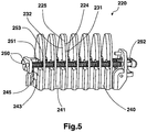
- the apparatus 1; 101 of figures 1 and 3 may comprise a complementary smoothing zone formed by a smoothing tooth device 220 illustrated in FIG. figure 5 and disposed in place of the toothed devices 20; 120.
- a smoothing tooth device 220 illustrated in FIG. figure 5 and disposed in place of the toothed devices 20; 120.
- This device is described in more detail in the French patent application No. 0854929 filed by the Applicant and incorporated herein by reference.
- the smoothing tooth device 220 mainly comprises a series of fixed blades 232 and a series of movable blades 231 arranged side by side in pairs parallel to each other and means for controlling the translational displacement of the movable blades 231 with respect to the blades. 232.
- the control means allow a momentary separation of the movable blades 231 relative to the fixed blades 232 at the opening of the jaws of the device so as to pass a lock of hair between the fixed and movable blades of each pair of smoothing blades.
- the device is illustrated at figure 5 in closed blade position.
- a movable blade 231 and an adjacent stationary blade 232 each have a surface facing each other which form two parallel surfaces thus defining two treatment surfaces 224, 225.
- the fixed blades 232 are secured to the upper surface of a block 240. Between each fixed blade 232 is defined a space for receiving a movable blade 231.
- the movable blades 231 are independent of each other and are embedded such as riders on a longitudinal median spine 241 of block 240.
- a heating element 245 is housed in a central groove 243 of the block 240 formed exactly within the median spine on which the movable blades 231 are embedded.
- the movable blades 231 cooperate with a control device comprising two walkers 250 formed by guide rods on which the blades 231 are slidably mounted. . Said blades 231 are each separated by a compression spring 251 and a spacer 253 integral with the player 250 and on which they abut in abutment.
- Each of the players 250 cooperates at one end 252 with an actuator (not shown in the figure) movable blades 231 relative to the fixed blades 232.
- the actuating device makes it possible, during the opening of the jaws of the apparatus, to cause the walkers 250 and thus the movable blades 231 to move backwards, causing said blades 231 to move away from the fixed blades 232.
- the actuating device When closing the jaws, the actuating device pushes the walkers 250 and therefore the movable blades 231 against the fixed blades 232, thereby pinching the locks of hair between said blades 231, 232.
- the teeth may have at their end a protrusion forming a comb to facilitate the insertion of the hair.
Landscapes
- Brushes (AREA)
- Dry Shavers And Clippers (AREA)
- Hair Curling (AREA)
- Cosmetics (AREA)
- Cleaning And Drying Hair (AREA)
- Surgical Instruments (AREA)
Description
- La présente invention concerne un appareil de coiffure qui est destiné à la mise en forme des cheveux, notamment le lissage des cheveux d'une personne.
- On connaît traditionnellement deux types d'appareils de coiffure permettant le lissage. Ces appareils sont soit des pinces à lisser, soit des sèche-cheveux équipés d'accessoires de lissage montés au niveau de l'extrémité soufflante de l'appareil.
- Les appareils du type pinces à lisser comportent généralement deux mâchoires pivotantes comprenant chacune une extrémité supportant une surface de traitement, au moins l'une des surfaces de traitement étant chauffée, l'autre étant prévue pour amener les cheveux en contact avec la première, notamment en passant d'une position d'ouverture des mâchoires permettant l'insertion des cheveux à une position de fermeture pour leur mise en contact avec la partie chauffante. L'autre extrémité des mâchoires forme deux demi-poignées faisant office de zone de préhension et permettant de passer de la position d'ouverture à celle de fermeture. Le passage se fait manuellement en pressant les deux demi-poignées articulées de l'appareil l'une vers l'autre pour amener la partie chauffante au contact des cheveux. Le lissage d'une mèche de cheveux s'effectue en déplaçant l'appareil le long de cette mèche, de la racine vers la pointe.
- Ces appareils de lissage permettent d'obtenir des lissages très « plaqués » ; les mèches de cheveux, une fois lissées, se trouvant plaquées sur la tête de l'utilisatrice de sorte que la coiffure perd un maximum de son volume.
- Cependant, la zone de contact des cheveux avec les surfaces de traitement est faible. Ainsi, en fonction du type de cheveux à traiter, il est nécessaire d'effectuer plusieurs passages de l'appareil sur une même mèche de cheveux. En effet dans les cas où les cheveux sont très ondulés ou très crépus, il est parfois nécessaire de repasser jusqu'à six fois pour pouvoir traiter les cheveux de la mèche en totalité.
- Une autre solution a été proposée dans le document
EP 1 124 466 au nom de la demanderesse où le dispositif de lissage est un accessoire destiné à être fixé à l'extrémité soufflante d'un sèche-cheveux, mais où les mèches sont introduites entre les surfaces lissantes de deux lames voisines qui sont poussées l'une vers l'autre par des moyens élastiques. Selon ce document, plusieurs lames élastiques sont agencées côte à côte, leurs extrémités d'attaque présentant des chanfreins d'introduction des cheveux à l'intérieur des lames. En fonctionnement, on introduit la partie frontale de l'accessoire dans la chevelure, ce qui a pour effet de séparer les cheveux en mèches fines qui s'introduisent alors automatiquement entre les lames voisines de l'accessoire. - Avec ce type d'appareil, la mèche de cheveux est donc répartie en plusieurs petites mèches indépendantes, ce qui permet d'augmenter la zone de contact des cheveux avec les surfaces de traitement et ainsi de diminuer le nombre de passages par rapport à une pince à lisser.
- Cependant, le souffle chaud de l'appareil ne permet pas un lissage plaqué comme dans une pince à lisser, la coiffure lissée possède un effet volume plus important.
- De plus, ce type d'appareil présente une structure volumineuse rendant son utilisation malaisée et peu pratique.
-
WO03/077702A - Un autre but de l'invention est un appareil de traitement des cheveux qui soit de structure simplifiée, compact et pouvant être industrialisé pour un faible coût.
- Ces buts sont atteints avec un appareil de coiffure selon la revendication 1.
- Selon l'invention, la mèche de cheveux se trouve pincée selon deux plans non parallèles, ce qui permet d'augmenter la surface des cheveux en contact avec les surfaces de traitement et ainsi augmenter l'efficacité d'un passage de l'appareil sur une mèche au niveau du résultat de lissage.
- En d'autres termes, la mèche de cheveux est pincée simultanément selon deux plans différents, ces deux plans étant perpendiculaires au sens de déplacement de l'appareil le long de la mèche de cheveux.
- Ainsi, le nombre de passage pour lisser une mèche de cheveux efficacement se trouve réduit par rapport au nombre de passages nécessaire avec un lisseur existant.
- Avantageusement, le premier plan et le deuxième plan sont perpendiculaires.
- Cette disposition permet d'obtenir une mèche de cheveux qui a localement une section sensiblement rectangulaire, du fait de son pincement par les surfaces de traitement perpendiculaires, la mèche étant ainsi traitée sur quatre faces. Ainsi, lors du déplacement de l'appareil pour le lissage d'une mèche de cheveux, on obtient une mise en forme rectiligne dès le premier passage.
- De préférence, la zone de lissage principale comporte au moins deux plaques s'étendant chacune dans un plan parallèle à l'axe longitudinal de chaque mâchoire.
- Avantageusement, la zone de lissage complémentaire comporte une pluralité de surfaces parallèles permettant de fractionner la mèche de cheveux en plusieurs mèches fines.
- Cette disposition permet par la multiplication des surfaces de traitement d'avoir un grand nombre de cheveux en contact avec ces surfaces et par le traitement de mèches fines d'avoir la majorité des cheveux de la mèche en contact avec les surfaces de traitement.
- La séparation en mèches fines permet également d'obtenir une température à coeur de la mèche suffisante pour un bon traitement.
- On obtient ainsi un lissage rapide et efficace de chaque mèche de la chevelure. La zone de lissage principale et la zone de lissage complémentaire sont thermiquement indépendantes.
- Par thermiquement indépendantes, on comprend que le chauffage de la zone de lissage principale peut être commandée de manière indépendante du chauffage de la zone de lissage complémentaire.
- Cette disposition permet d'ajuster indépendamment la température de chaque zone de lissage en fonction du type de cheveux, de l'état des cheveux ou du résultat désiré.
- Avantageusement, la zone de lissage complémentaire est amovible.
- En d'autres termes, la zone de lissage complémentaire comportant un nombre et une forme de surfaces de traitement donnés peut être remplacée par une autre zone de lissage complémentaire comportant un nombre et une forme de surfaces de traitement différents.
- Cette disposition permet d'adapter la zone de lissage complémentaire suivant le type de cheveux et le type de résultat de lissage désiré. La zone de lissage complémentaire est située en amont et/ou en aval de la zone de lissage principale.
- Cette disposition permet de proposer une variante de réalisation de l'invention dans une pince à lisser traditionnelle de manière très simple et économique. Avantageusement, la zone de lissage complémentaire est agencée sur la mâchoire inférieure et la mâchoire supérieure comporte un capot de protection agencé en regard de la zone de lissage complémentaire.
- Cette disposition permet de créer une enceinte chaude dans laquelle est enfermée la zone de lissage complémentaire et les cheveux en position fermée de l'appareil, ce qui a l'avantage de minimiser les pertes thermiques dans l'air et donc d'augmenter la performance de l'appareil. Le capot de protection permet aussi d'entrainer les mèches fines de cheveux dans les surfaces de traitement favorisant ainsi l'échange thermique.
- Avantageusement, la zone de lissage complémentaire est située à l'intérieur de la zone de lissage principale.
- Cette disposition permet d'obtenir un appareil avec un axe de symétrie dans le sens longitudinal. Ainsi, l'appareil peut être utilisé indifféremment par la main droite ou la main gauche.
- Dans une variante de réalisation, la zone de lissage complémentaire comporte une rangée de paires de lames de lissage agencées en vis-à-vis, au moins l'une des lames de chaque paire étant montée mobile par rapport à une lame adjacente fixe de manière à permettre le pincement d'une mèche de cheveux entre deux surfaces de traitement des lames en vis-à-vis d'une même paire.
- Cette disposition permet de dissocier l'effort de pinçage exercé sur la mèche par la zone de lissage principale de l'effort de pinçage exercé sur la mèche par la zone de lissage complémentaire.
- L'invention sera mieux comprise à l'étude des modes de réalisation pris à titre nullement limitatif et illustrés dans les figures annexées dans lesquelles :
- La
figure 1 illustre une vue en perspective du dessous de l'appareil selon un mode particulier de réalisation de l'invention. - La
figure 2 illustre une vue en perspective du dessus de l'appareil de lafigure 1 . - La
figure 3 illustre une vue en perspective du dessous de l'appareil selon un autre mode de réalisation de l'invention. - La
figure 4 illustre une vue en perspective du dessus de l'appareil de lafigure 3 . - La
figure 5 illustre une vue en perspective d'une zone de lissage complémentaire selon une variante de réalisation de l'invention. - Les
figures 1 et 2 illustrent un appareil 1 qui est un fer à lisser selon un mode préféré de réalisation de l'invention, l'appareil étant en position ouverte. L'appareil 1 comprend une mâchoire 2 supérieure et une mâchoire 3 inférieure montées pivotantes autour d'une articulation 4. L'articulation est munie à l'arrière d'un embout apte à recevoir un connecteur rotatif 30 pour un câble d'alimentation en énergie électrique principal. - Chaque mâchoire comprend une partie adjacente à l'articulation 4, formant une zone de préhension de type pince constituée par une demi-poignée supérieure 5 et une demi-poignée inférieure 6.
- La mâchoire 2 supérieure comprend en partie avant un boîtier 7 apte à recevoir une plaque 10 de lissage. La mâchoire 3 inférieure comprend en partie avant un boîtier 8 apte à recevoir une plaque 11 et un dispositif à dents 20 de lissage. La plaque 10 et la plaque 11 forment une zone de lissage principale et le dispositif à dents 20 forme une zone de lissage complémentaire. Les boîtiers 7, 8 sont avantageusement réalisés en une matière plastique par une technique d'injection.
- La plaque 10, la plaque 11 et le dispositif à dents 20 de lissage sont chacun en contact thermique avec un élément chauffant (non représentés sur les figures) qui peut être un élément chauffant électrique du type résistif, à CTP, à infrarouges, etc. alimenté en énergie par un interrupteur 9 recevant l'alimentation du câble principal de l'appareil. Les plaques 10, 11 et le dispositif à dents 20 de lissage sont réalisés en un matériau métallique bon conducteur de la chaleur du type aluminium ou ses alliages, cuivre ou ses alliages ou en acier.
- Conformément à la
figure 2 , le dispositif à dents 20 de lissage comporte un socle 21 parallélépipédique disposé latéralement à la plaque 11. Le socle 21 comprend une face supérieure 23 disposée dans le même plan que la face supérieure 12 de la plaque 11. Le socle 21 comporte une série de quinze dents 22 agencées parallèlement formant sensiblement un peigne à dents aplaties. Les dents 22 sont solidaires par leur base au socle 21 et ont sensiblement une forme ogivale ou de pointe de flèche permettant de fractionner une mèche de cheveux en plusieurs mèches fines. Chaque dent 22 comporte deux surfaces parallèles définissant deux surfaces 24, 25 latérales de traitement. Deux surfaces latérales de traitement en vis-à-vis appartenant à deux dents successives ainsi que la partie de la face supérieure 23 entre les deux dents 22 définissent un réceptacle en forme de U pour une mèche fine. - Le boîtier 7 comporte un capot 15 agencé latéralement à la plaque 10, en vis-à-vis du dispositif à dents 20 de lissage. Le capot 15 comporte une ouverture longitudinale 16 recevant les dents 22 lorsque l'appareil est en position fermée. Le capot peut permettre d'éviter le contact du cuir chevelu avec les dents 22. Le capot 15 comporte également un bord externe 17
- A titre de variante, le socle 21 peut être agencé de manière amovible à l'aide d'un dispositif en queue d'aronde sur une base disposée dans le boitier 8 (non illustré dans les figures). Ainsi, l'utilisatrice peut adapter sur l'appareil un dispositif à dents avec des dents plus ou moins hautes, des dents plus ou moins espacées en fonction du type de chevelure et du type de lissage désiré.
- En fonctionnement, après la mise en température de l'appareil 1, l'utilisatrice insère une mèche de cheveux entre les deux mâchoires 2, 3 supportant les plaques 10, 11 et le dispositif à dents 20 de lissage, de préférence en plaçant les plaques 10, 11 au plus près du cuir chevelu. Puis elle exerce une pression sur les demi-poignées 5, 6 pour fermer l'appareil. La mèche se trouve ainsi pincée entre les deux plaques 10, 11 et fractionnée en mèches fines entre les dents 22 par la poussée du bord externe 17 du capot 15. Le pincement de la mèche et la poussée du bord externe 17 ont pour effet d'amener les cheveux des mèches fines au contact des surfaces latérales des dents 22, ce qui revient à pincer les mèches fines dans un plan perpendiculaire aux plaques 10, 11. L'utilisatrice déplace ensuite l'appareil 1 le long de la mèche de cheveux, de la racine vers la pointe des cheveux en maintenant l'appareil fermé. Le déplacement de l'appareil renforce la pression des cheveux sur les surfaces latérales des dents 22.
- Les
figures 3 et 4 illustrent un appareil 101 qui est un fer à lisser selon un autre mode de réalisation de l'invention, l'appareil étant en position ouverte. L'appareil 101 comprend une mâchoire 102 supérieure et une mâchoire 103 inférieure montées pivotantes autour d'une articulation 104. L'articulation est munie à l'arrière d'un embout apte à recevoir un connecteur rotatif 130 pour un câble d'alimentation en énergie électrique principal. - Chaque mâchoire comprend une partie adjacente à l'articulation 104, formant une zone de préhension de type pince constituée par une demi-poignée supérieure 105 et une demi poignée inférieure 106.
- La mâchoire 102 supérieure comprend en partie avant un boîtier 107 apte à recevoir une plaque 110 de lissage. La mâchoire inférieure 103 comprend en partie avant un boîtier 108 apte à recevoir une plaque 111 de lissage. La plaque 111 comporte un dispositif à dents 120 de lissage comprenant une série de quinze dents 122 agencées parallèlement formant sensiblement un peigne à dents aplaties. La plaque 110 et la plaque 111 forment une zone de lissage principale et le dispositif à dents 120 forme une zone de lissage complémentaire.
- La série de dents 122 s'étend selon l'axe longitudinal de la plaque 111, chaque dent 122 étant sensiblement centrée dans l'axe transversal de la plaque 111. Les dents 122 sont solidaires par leur base à la plaque 111 et ont sensiblement une forme ogivale ou de pointe de flèche permettant de fractionner une mèche de cheveux en plusieurs mèches fines. Chaque dent 122 comporte deux surfaces parallèles définissant deux surfaces latérales 124, 125 de traitement.
- Chaque plaque 110, 111 renferme un élément chauffant (non représentés sur les figures) alimenté en énergie par un interrupteur 109 recevant l'alimentation du câble principal de l'appareil.
- La plaque 111 comporte une ouverture longitudinale 116 recevant les dents 122 lorsque l'appareil est en position fermée.
- En fonctionnement, après la mise en température de l'appareil 101, l'utilisatrice insère une mèche de cheveux entre les deux mâchoires 102, 103 supportant la plaque 110 et la plaque 111 munie du dispositif à dents 120 de lissage, de préférence en plaçant l'appareil au plus près du cuir chevelu. Ainsi, cette mèche se répartit en mèches fines entre les dents 122. Puis elle exerce une pression sur les demi-poignées 105, 106 pour fermer l'appareil. La mèche se trouve ainsi pincée entre les deux plaques 110, 111. Ce pincement de la mèche a pour effet d'amener les cheveux des mèches fines au contact des surfaces latérales des dents 122, ce qui revient à pincer les mèches fines dans un plan perpendiculaire aux plaques 110, 111. L'utilisatrice déplace ensuite l'appareil 101 le long de la mèche de cheveux, de la racine vers la pointe des cheveux en maintenant l'appareil fermé. La traction exercée sur la mèche lors du déplacement de l'appareil renforce la pression des cheveux sur les surfaces latérales des dents 122.
- Dans un autre mode de réalisation, l'appareil 1 ; 101 des
figures 1 et3 peut comprendre une zone de lissage complémentaire formée par un dispositif à dents 220 de lissage illustré à lafigure 5 et disposé à la place des dispositifs à dents 20; 120. Ce dispositif est décrit plus en détails dans la demande de brevet français N°0854929 - Le dispositif à dents 220 de lissage comporte principalement une série de lames fixes 232 et une série de lames mobiles 231 agencées côte à côte par paires parallèlement les unes aux autres et des moyens de commandes de déplacement en translation des lames mobiles 231 par rapport aux lames fixes 232. Les moyens de commande permettent un écartement momentané des lames mobiles 231 par rapport aux lames fixes 232 à l'ouverture des mâchoires de l'appareil de manière à faire passer une mèche de cheveux entre les lames fixe et mobile de chaque paire de lames de lissage. Le dispositif est illustré à la
figure 5 en position lames fermées. - Une lame 231 mobile et une lame 232 adjacente fixe comportent chacune une surface en vis-à-vis qui forment deux surfaces parallèles définissant ainsi deux surfaces de traitement 224, 225.
- Les lames fixes 232 sont solidaires de la surface supérieure d'un bloc 240. Entre chaque lame fixe 232 est délimité un espace destiné à recevoir une lame mobile 231. De façon avantageuse, les lames mobiles 231 sont indépendantes les unes des autres et sont enchâssées tels des cavaliers sur une épine médiane longitudinale 241 du bloc 240.
- Afin de procurer un chauffage homogène et uniforme des lames fixes 232, un élément chauffant 245 est logé dans une rainure centrale 243 du bloc 240 formée exactement au sein de l'épine médiane sur laquelle les lames mobiles 231 sont enchâssées.
- Afin de permettre le passage de mèches de cheveux que l'on souhaite lisser entre chaque paire de lames, les lames mobiles 231 coopèrent avec un dispositif de commande comportant deux baladeurs 250 formés par des tiges de guidage sur lesquelles les lames 231 sont montées à coulissement. Lesdites lames 231 sont chacune séparées par un ressort de compression 251 et une entretoise 253 solidaire du baladeur 250 et sur laquelle elles reposent en butée.
- Chacun des baladeurs 250 coopère en une extrémité 252 avec un dispositif d'actionnement (non représenté sur la figure) des lames mobiles 231 par rapport aux lames fixes 232.
- Le dispositif d'actionnement permet lors de l'ouverture des mâchoires de l'appareil de provoquer un mouvement de recul des baladeurs 250 et donc des lames mobiles 231, provoquant un écartement desdites lames 231 des lames fixes 232.
- Lors de la fermeture des mâchoires, le dispositif d'actionnement repousse les baladeurs 250 et donc les lames mobiles 231 contre les lames fixes 232, pinçant de la sorte les mèches de cheveux entre lesdites lames 231, 232.
- Bien entendu, l'invention n'est nullement limitée au mode de réalisation décrit et illustré qui n'a été donné qu'à titre d'exemple. Des modifications restent possibles, notamment du point de vue de la constitution des divers éléments ou par substitution d'équivalents techniques, sans sortir pour autant du domaine de protection de l'invention définie par les revendications. Ainsi, les dents peuvent comporter à leur extrémité une excroissance formant un peigne pour faciliter l'insertion des cheveux.
Claims (8)
- Appareil de coiffure (1 ; 101) comportant deux ensembles de surfaces de traitement pour venir pincer une mèche de cheveux, les deux ensembles de surfaces de traitement étant respectivement portés par des mâchoires (2, 3 ; 102, 103) disposées en vis à vis, lesdits ensembles de surfaces de traitement comportant au moins une zone de lissage principale (10, 11 ; 110, 111) chauffante permettant de pincer la mèche de cheveux selon un premier plan et une zone de lissage complémentaire (20; 120; 220) chauffante permettant de pincer la mèche de cheveux selon un deuxième plan non parallèle au premier plan, la zone de lissage complémentaire (20) étant située en amont et/ou en aval de la zone de lissage principale (10, 11), caractérisé en ce que la zone de lissage principale et la zone de lissage complémentaire sont thermiquement indépendantes.
- Appareil de coiffure (1 ; 101) selon la revendication 1, caractérisé en ce que le premier plan et le deuxième plan sont perpendiculaires.
- Appareil de coiffure (1 ; 101) selon l'une quelconque des revendications 1 à 2, caractérisé en ce que la zone de lissage principale comporte au moins deux plaques (10, 11 ; 110, 111) s'étendant chacune dans un plan parallèle à l'axe longitudinal de chaque mâchoire (2, 3 ; 102, 103).
- Appareil de coiffure (1 ; 101) selon l'une quelconque des revendications 1 à 3, caractérisé en ce que la zone de lissage complémentaire (20 ; 120 ; 220) comporte une pluralité de surfaces parallèles (24, 25 ; 124, 125 ; 224, 225) permettant de fractionner la mèche de cheveux en plusieurs mèches fines.
- Appareil de coiffure (1 ; 101) selon l'une quelconque des revendications 1 à 4, caractérisé en ce que la zone de lissage complémentaire (20, 120, 220) est amovible.
- Appareil de coiffure (1) selon la revendication 1, caractérisé en ce que la zone de lissage complémentaire (20) est agencée sur la mâchoire (3) inférieure et en ce que la mâchoire supérieure (2) comporte un capot (15) de protection agencé en regard de la zone de lissage complémentaire (20).
- Appareil de coiffure (1 ; 101) selon l'une des revendications 1 à 6 caractérisé en ce que la zone de lissage complémentaire (220) comporte une rangée de paires de lames de lissage agencées en vis-à-vis, au moins l'une des lames (231) de chaque paire étant montée mobile par rapport à une lame (232) adjacente fixe de manière à permettre le pincement d'une mèche de cheveux entre deux surfaces de traitement (224, 225) des lames en vis-à-vis d'une même paire.
- Appareil de coiffure (1 ; 101) selon la revendication 4 , caractérisé en ce que la zone de lissage principale chauffante est formée d'une première plaque (10) et d'une deuxième plaque (11) et la zone de lissage complémentaire est formée d'un dispositif à dents (20), la première plaque (10), la deuxième plaque (11) et le dispositif à dents (20) de lissage étant chacun en contact thermique avec un élément chauffant.
Applications Claiming Priority (1)
| Application Number | Priority Date | Filing Date | Title |
|---|---|---|---|
| FR0900168A FR2940893B1 (fr) | 2009-01-15 | 2009-01-15 | Appareil de coiffure |
Publications (2)
| Publication Number | Publication Date |
|---|---|
| EP2208433A1 EP2208433A1 (fr) | 2010-07-21 |
| EP2208433B1 true EP2208433B1 (fr) | 2017-08-09 |
Family
ID=41126296
Family Applications (3)
| Application Number | Title | Priority Date | Filing Date |
|---|---|---|---|
| EP10703315.1A Active EP2378915B1 (fr) | 2009-01-15 | 2010-01-15 | Appareil de coiffure |
| EP10356005.8A Active EP2208433B1 (fr) | 2009-01-15 | 2010-01-15 | Appareil de coiffure |
| EP10703316.9A Active EP2378916B1 (fr) | 2009-01-15 | 2010-01-15 | Appareil de coiffure a machoires |
Family Applications Before (1)
| Application Number | Title | Priority Date | Filing Date |
|---|---|---|---|
| EP10703315.1A Active EP2378915B1 (fr) | 2009-01-15 | 2010-01-15 | Appareil de coiffure |
Family Applications After (1)
| Application Number | Title | Priority Date | Filing Date |
|---|---|---|---|
| EP10703316.9A Active EP2378916B1 (fr) | 2009-01-15 | 2010-01-15 | Appareil de coiffure a machoires |
Country Status (9)
| Country | Link |
|---|---|
| US (1) | US8789539B2 (fr) |
| EP (3) | EP2378915B1 (fr) |
| KR (1) | KR101677776B1 (fr) |
| CN (3) | CN102281791B (fr) |
| BR (3) | BRPI1006793A2 (fr) |
| CA (1) | CA2690326A1 (fr) |
| ES (3) | ES2640039T3 (fr) |
| FR (2) | FR2940893B1 (fr) |
| WO (2) | WO2010081968A1 (fr) |
Families Citing this family (45)
| Publication number | Priority date | Publication date | Assignee | Title |
|---|---|---|---|---|
| FR2940893B1 (fr) * | 2009-01-15 | 2012-12-21 | Seb Sa | Appareil de coiffure |
| JP2011098000A (ja) * | 2009-11-04 | 2011-05-19 | Panasonic Electric Works Co Ltd | ヘアーアイロン装置 |
| ITMI20091946A1 (it) * | 2009-11-06 | 2011-05-07 | Tenacta Group Spa | Dispositivo per arricciare e/o modellare i capelli |
| IT1398942B1 (it) * | 2010-03-17 | 2013-03-28 | Tenacta Group Spa | Apparecchiatura elettrica per modellare i capelli |
| CN201822159U (zh) * | 2010-04-09 | 2011-05-11 | 建福实业有限公司 | 电动定型烫发器 |
| DE102010030223A1 (de) * | 2010-06-17 | 2011-12-22 | BSH Bosch und Siemens Hausgeräte GmbH | Haarglätter |
| FR2961667B1 (fr) * | 2010-06-25 | 2012-08-17 | Seb Sa | Appareil de coiffure a machoires |
| GB2477834B (en) * | 2010-08-31 | 2012-02-01 | Jemella Ltd | Hair styling appliance |
| KR200456707Y1 (ko) * | 2011-05-17 | 2011-11-14 | 주종현 | 헤어 매직기 |
| EP2601858A1 (fr) * | 2011-12-09 | 2013-06-12 | Dickson Industrial Co., Ltd. | Appareil de coiffure |
| FR2989253B1 (fr) * | 2012-04-12 | 2014-05-16 | Seb Sa | Appareil de coiffure a machoires avec peigne retractable |
| DE102012210274A1 (de) * | 2012-06-19 | 2013-12-19 | BSH Bosch und Siemens Hausgeräte GmbH | Haargestaltungsvorrichtung mit Feuchteregulierung |
| USD735477S1 (en) * | 2012-07-11 | 2015-08-04 | Stacy Anderson | Brush attachment for a flat iron |
| US20150335121A1 (en) * | 2012-12-18 | 2015-11-26 | Koninklijke Philips N.V. | Hair straightener |
| ITMI20130074A1 (it) * | 2013-01-21 | 2014-07-22 | Tenacta Group Spa | Dispositivo multifunzione per modellare i capelli |
| US8955526B2 (en) | 2013-03-16 | 2015-02-17 | Tyme Llc | Hair styling device |
| JP5903195B2 (ja) * | 2013-07-24 | 2016-04-13 | コーニンクレッカ フィリップス エヌ ヴェKoninklijke Philips N.V. | ヘアスタイリングデバイス |
| US9181651B2 (en) * | 2014-01-07 | 2015-11-10 | Susan Bishop | Hand-held clothing iron |
| US9528220B2 (en) * | 2014-02-19 | 2016-12-27 | Collar Perfect, LLC | Convertible iron |
| SG11201701087TA (en) * | 2014-06-13 | 2017-03-30 | Roholm Ltd | Hair conditioning treatment apparatus and method |
| USD776871S1 (en) | 2014-06-20 | 2017-01-17 | Tyme, LLC | Hair styling device |
| FR3023138B1 (fr) * | 2014-07-02 | 2018-07-13 | L'oreal | Appareil de coiffure pour former des boucles de tailles differentes |
| EP3171733A1 (fr) * | 2014-07-24 | 2017-05-31 | The Procter and Gamble Company | Procédé de mesure et/ou de réglage de la résistance de peignage à l'aide d'une brosse |
| US20160302546A1 (en) * | 2015-04-17 | 2016-10-20 | Wenzhou Lena Electric Technology Corp. | Hair curler |
| GB2542207B (en) * | 2015-09-14 | 2021-06-16 | Jemella Ltd | Apparatus and method for drying hair |
| FR3042957B1 (fr) * | 2015-11-02 | 2017-11-17 | Seb Sa | Appareil de coiffure de type lisseur avec peigne optimise |
| FR3042958B1 (fr) * | 2015-11-02 | 2017-11-17 | Seb Sa | Appareil de coiffure de type lisseur avec peigne optimise |
| RU2674457C1 (ru) * | 2015-11-25 | 2018-12-10 | Конинклейке Филипс Н.В. | Приспособление для укладки волос |
| FR3045285B1 (fr) * | 2015-12-18 | 2018-02-02 | L'oreal | Dispositif de traitement de la chevelure |
| IL243841B (en) * | 2016-01-28 | 2019-08-29 | Mor Nissim | Hair straightener |
| US20180055178A1 (en) * | 2016-08-26 | 2018-03-01 | Bianca Alberti | Palm roller for dreadlock formation |
| EP3460433A1 (fr) | 2017-09-20 | 2019-03-27 | Koninklijke Philips N.V. | Dispositif de mesure de propriétés de cheveux |
| RU2743358C1 (ru) * | 2017-12-21 | 2021-02-17 | Фарук Системз, Инк. | Утюжок-выпрямитель для укладки волос (варианты) |
| FR3076190B1 (fr) * | 2017-12-29 | 2021-10-15 | Seb Sa | Appareil de coiffage automatique |
| FR3076189B1 (fr) * | 2017-12-29 | 2021-09-10 | Seb Sa | Appareil de coiffage a cinematique amelioree |
| WO2019238961A1 (fr) * | 2018-06-15 | 2019-12-19 | Hd3 Limited | Dispositif de coiffure |
| GB2582558B (en) | 2019-03-22 | 2022-08-10 | Dyson Technology Ltd | A hair styling appliance |
| JP7320751B2 (ja) * | 2019-08-29 | 2023-08-04 | パナソニックIpマネジメント株式会社 | ヘアーアイロン |
| FR3101526B1 (fr) | 2019-10-02 | 2021-10-01 | Oreal | Dispositif de traitement de la chevelure comportant un peigne chauffant |
| GB2594968A (en) * | 2020-05-13 | 2021-11-17 | Timothy Low Stephen | Hair waving apparatus |
| FR3122556B1 (fr) | 2021-05-07 | 2023-06-02 | Oreal | Appareil de mise en forme d’une chevelure |
| GB2614547B (en) | 2022-01-06 | 2024-09-18 | Dyson Technology Ltd | Hair styling accessory |
| FR3134689B1 (fr) | 2022-04-21 | 2025-08-29 | Oreal | Dispositif de traitement de la chevelure comportant un peigne |
| FR3146394A1 (fr) | 2023-03-10 | 2024-09-13 | L'oreal | Dispositif de traitement des cheveux. |
| GB2629817A (en) * | 2023-05-11 | 2024-11-13 | Dyson Operations Pte Ltd | Hair styling appliance |
Family Cites Families (29)
| Publication number | Priority date | Publication date | Assignee | Title |
|---|---|---|---|---|
| FR854929A (fr) | 1938-05-21 | 1940-04-27 | V G Mfg Co | Dispositif pour l'enregistrement de phonogrammes |
| JPH0779730B2 (ja) * | 1986-02-14 | 1995-08-30 | 松下電工株式会社 | ヘア−アイロン |
| JP3000262B2 (ja) * | 1996-05-23 | 2000-01-17 | 豊作 瀧前 | 縮れ毛矯正アイロン |
| FR2785159B1 (fr) | 1998-10-30 | 2000-12-22 | Seb Sa | Accessoire pour le lissage des cheveux |
| JP2001104036A (ja) * | 1999-10-12 | 2001-04-17 | Keisuke Wada | ヘアーアイロン |
| KR200255099Y1 (ko) * | 2001-06-13 | 2001-12-13 | 조옥남 | 착탈이 간편한 방열판을 가지는 헤어 스타일링기 |
| MXPA04008975A (es) * | 2002-03-15 | 2005-06-17 | Habibi Masood | Dispositivo dentado termico para peinar el cabello y metodo de fabricacion. |
| ES2287288T3 (es) * | 2002-06-26 | 2007-12-16 | Matsushita Electric Works, Ltd. | Tenacilla para cabello. |
| TW200520707A (en) * | 2003-08-01 | 2005-07-01 | Phild Co Ltd | Hair iron |
| KR200341776Y1 (ko) * | 2003-10-06 | 2004-02-14 | 구레이쓰이온코리아 주식회사 | 커얼용 헤어 아이론 |
| ATE415834T1 (de) * | 2004-11-01 | 2008-12-15 | K I C A Inc | Haareisen |
| KR100596704B1 (ko) * | 2005-03-02 | 2006-07-10 | 최영범 | 완충부재가 부착된 고대기 |
| DE102005010568A1 (de) * | 2005-03-04 | 2006-09-07 | Braun Gmbh | Haarformgerät |
| EA200800141A1 (ru) * | 2005-08-26 | 2009-10-30 | Джозеф Мурад | Устройство для укладки волос |
| JP4839800B2 (ja) * | 2005-11-25 | 2011-12-21 | パナソニック電工株式会社 | 超音波ヘアセット器 |
| KR200417662Y1 (ko) * | 2006-03-23 | 2006-06-02 | 우장근 | 미용용 고데기 |
| US7445012B2 (en) * | 2006-04-12 | 2008-11-04 | Takashi Mukai | Hair iron |
| FR2913316B1 (fr) * | 2007-03-07 | 2011-08-26 | Seb Sa | Appareil de coiffure |
| US20080283080A1 (en) * | 2007-05-15 | 2008-11-20 | Masood Habibi | Hair styling device |
| BRPI0706046A2 (pt) * | 2007-06-26 | 2011-03-22 | Takashi Mukai | prancha para cabelo |
| WO2009007823A2 (fr) * | 2007-07-10 | 2009-01-15 | Dickson Industrial Co., Ltd. | Fer friser les cheveux |
| CN201899028U (zh) * | 2007-10-04 | 2011-07-20 | 康奈尔有限公司 | 用于定型头发的直发烫钳 |
| US20090107518A1 (en) * | 2007-10-29 | 2009-04-30 | Cohen Martin A | Hair styling iron with raised fins |
| CA2676561C (fr) * | 2008-08-23 | 2012-10-16 | Farouk Systems, Inc. | Fer a friser |
| FR2940893B1 (fr) * | 2009-01-15 | 2012-12-21 | Seb Sa | Appareil de coiffure |
| KR100979136B1 (ko) * | 2009-11-26 | 2010-09-02 | (주) 에스엠세라믹 | 머리 미용기구 |
| US8082929B2 (en) * | 2010-01-21 | 2011-12-27 | Ghd Korea, Inc. | Hair iron |
| IT1398942B1 (it) * | 2010-03-17 | 2013-03-28 | Tenacta Group Spa | Apparecchiatura elettrica per modellare i capelli |
| US9138038B2 (en) * | 2011-05-20 | 2015-09-22 | Spectrum Brands, Inc. | Hair styling apparatus having hair-protection function |
-
2009
- 2009-01-15 FR FR0900168A patent/FR2940893B1/fr active Active
- 2009-04-15 FR FR0952474A patent/FR2940894B1/fr not_active Expired - Fee Related
-
2010
- 2010-01-15 CN CN201080004624.0A patent/CN102281791B/zh active Active
- 2010-01-15 ES ES10703316.9T patent/ES2640039T3/es active Active
- 2010-01-15 CA CA2690326A patent/CA2690326A1/fr not_active Abandoned
- 2010-01-15 EP EP10703315.1A patent/EP2378915B1/fr active Active
- 2010-01-15 BR BRPI1006793A patent/BRPI1006793A2/pt not_active IP Right Cessation
- 2010-01-15 WO PCT/FR2010/000034 patent/WO2010081968A1/fr not_active Ceased
- 2010-01-15 EP EP10356005.8A patent/EP2208433B1/fr active Active
- 2010-01-15 ES ES10703315.1T patent/ES2686887T3/es active Active
- 2010-01-15 KR KR1020117018860A patent/KR101677776B1/ko not_active Expired - Fee Related
- 2010-01-15 BR BRPI1007140A patent/BRPI1007140A2/pt not_active IP Right Cessation
- 2010-01-15 US US13/144,240 patent/US8789539B2/en not_active Expired - Fee Related
- 2010-01-15 BR BRPI1000086-0A patent/BRPI1000086A2/pt not_active IP Right Cessation
- 2010-01-15 CN CN201080004411.8A patent/CN102271549B/zh active Active
- 2010-01-15 WO PCT/FR2010/000035 patent/WO2010081969A1/fr not_active Ceased
- 2010-01-15 CN CN2010200004476U patent/CN201814058U/zh not_active Expired - Lifetime
- 2010-01-15 EP EP10703316.9A patent/EP2378916B1/fr active Active
- 2010-01-15 ES ES10356005.8T patent/ES2640037T3/es active Active
Non-Patent Citations (1)
| Title |
|---|
| None * |
Also Published As
| Publication number | Publication date |
|---|---|
| EP2378916A1 (fr) | 2011-10-26 |
| CN102281791A (zh) | 2011-12-14 |
| WO2010081968A1 (fr) | 2010-07-22 |
| EP2378916B1 (fr) | 2017-08-09 |
| CN102271549A (zh) | 2011-12-07 |
| EP2378915A1 (fr) | 2011-10-26 |
| US8789539B2 (en) | 2014-07-29 |
| FR2940893B1 (fr) | 2012-12-21 |
| WO2010081969A1 (fr) | 2010-07-22 |
| KR20110122118A (ko) | 2011-11-09 |
| EP2208433A1 (fr) | 2010-07-21 |
| FR2940894B1 (fr) | 2013-08-16 |
| CA2690326A1 (fr) | 2010-07-15 |
| FR2940894A1 (fr) | 2010-07-16 |
| KR101677776B1 (ko) | 2016-11-18 |
| BRPI1007140A2 (pt) | 2016-02-23 |
| EP2378915B1 (fr) | 2018-08-01 |
| BRPI1006793A2 (pt) | 2019-03-26 |
| BRPI1000086A2 (pt) | 2011-03-29 |
| ES2640037T3 (es) | 2017-10-31 |
| US20120024311A1 (en) | 2012-02-02 |
| ES2640039T3 (es) | 2017-10-31 |
| ES2686887T3 (es) | 2018-10-22 |
| CN201814058U (zh) | 2011-05-04 |
| CN102271549B (zh) | 2015-01-21 |
| CN102281791B (zh) | 2014-10-15 |
| FR2940893A1 (fr) | 2010-07-16 |
Similar Documents
| Publication | Publication Date | Title |
|---|---|---|
| EP2208433B1 (fr) | Appareil de coiffure | |
| EP2145557B1 (fr) | Appareil de coiffure à pression continue | |
| EP2120629B1 (fr) | Appareil de coiffure | |
| EP2827735B1 (fr) | Appareil de coiffure | |
| EP1429638B1 (fr) | Dispositif defriseur et modeleur de cheveux. | |
| EP2462831B1 (fr) | Accessoire de mise en forme de cheveux | |
| WO2009077676A2 (fr) | Appareil de traitement des cheveux | |
| WO2016001583A1 (fr) | Appareil de coiffure pour former des boucles de tailles differentes | |
| WO2015173508A1 (fr) | Appareil de coiffure a vapeur avec moyens de confinement de la vapeur | |
| EP2312967B1 (fr) | Dispositif de lissage des cheveux integrant des moyens de chauffage | |
| EP2258232B1 (fr) | Dispositif de traitement des cheveux et appareil de traitement des cheveux comportant un tel dispositif | |
| FR3023138A1 (fr) | Appareil de coiffure pour former des boucles de tailles differentes | |
| WO2008129172A2 (fr) | Appareil de coiffure | |
| FR2979202A1 (fr) | Appareil de coiffure a rayonnement | |
| EP2399481B1 (fr) | Appareil de coiffure à mâchoires | |
| EP2584930B1 (fr) | Appareil de coiffure a machoires | |
| EP2700328A2 (fr) | Appareil de coiffure à ergonomie optimisée | |
| FR3134693A1 (fr) | Dispositif de traitement de la chevelure | |
| FR3134691A1 (fr) | Dispositif de traitement de la chevelure | |
| EP0679349A1 (fr) | Dispositif permettant l'ondulation des cheveux |
Legal Events
| Date | Code | Title | Description |
|---|---|---|---|
| PUAI | Public reference made under article 153(3) epc to a published international application that has entered the european phase |
Free format text: ORIGINAL CODE: 0009012 |
|
| AK | Designated contracting states |
Kind code of ref document: A1 Designated state(s): AT BE BG CH CY CZ DE DK EE ES FI FR GB GR HR HU IE IS IT LI LT LU LV MC MK MT NL NO PL PT RO SE SI SK SM TR |
|
| AX | Request for extension of the european patent |
Extension state: AL BA RS |
|
| 17P | Request for examination filed |
Effective date: 20110111 |
|
| 17Q | First examination report despatched |
Effective date: 20160511 |
|
| RAP1 | Party data changed (applicant data changed or rights of an application transferred) |
Owner name: SEB S.A. |
|
| GRAP | Despatch of communication of intention to grant a patent |
Free format text: ORIGINAL CODE: EPIDOSNIGR1 |
|
| INTG | Intention to grant announced |
Effective date: 20170302 |
|
| GRAS | Grant fee paid |
Free format text: ORIGINAL CODE: EPIDOSNIGR3 |
|
| GRAA | (expected) grant |
Free format text: ORIGINAL CODE: 0009210 |
|
| AK | Designated contracting states |
Kind code of ref document: B1 Designated state(s): AT BE BG CH CY CZ DE DK EE ES FI FR GB GR HR HU IE IS IT LI LT LU LV MC MK MT NL NO PL PT RO SE SI SK SM TR |
|
| REG | Reference to a national code |
Ref country code: GB Ref legal event code: FG4D Free format text: NOT ENGLISH |
|
| REG | Reference to a national code |
Ref country code: CH Ref legal event code: EP Ref country code: AT Ref legal event code: REF Ref document number: 915866 Country of ref document: AT Kind code of ref document: T Effective date: 20170815 |
|
| REG | Reference to a national code |
Ref country code: IE Ref legal event code: FG4D Free format text: LANGUAGE OF EP DOCUMENT: FRENCH |
|
| REG | Reference to a national code |
Ref country code: DE Ref legal event code: R096 Ref document number: 602010044227 Country of ref document: DE |
|
| REG | Reference to a national code |
Ref country code: ES Ref legal event code: FG2A Ref document number: 2640037 Country of ref document: ES Kind code of ref document: T3 Effective date: 20171031 |
|
| REG | Reference to a national code |
Ref country code: NL Ref legal event code: MP Effective date: 20170809 |
|
| REG | Reference to a national code |
Ref country code: LT Ref legal event code: MG4D |
|
| REG | Reference to a national code |
Ref country code: AT Ref legal event code: MK05 Ref document number: 915866 Country of ref document: AT Kind code of ref document: T Effective date: 20170809 |
|
| PG25 | Lapsed in a contracting state [announced via postgrant information from national office to epo] |
Ref country code: NO Free format text: LAPSE BECAUSE OF FAILURE TO SUBMIT A TRANSLATION OF THE DESCRIPTION OR TO PAY THE FEE WITHIN THE PRESCRIBED TIME-LIMIT Effective date: 20171109 Ref country code: HR Free format text: LAPSE BECAUSE OF FAILURE TO SUBMIT A TRANSLATION OF THE DESCRIPTION OR TO PAY THE FEE WITHIN THE PRESCRIBED TIME-LIMIT Effective date: 20170809 Ref country code: SE Free format text: LAPSE BECAUSE OF FAILURE TO SUBMIT A TRANSLATION OF THE DESCRIPTION OR TO PAY THE FEE WITHIN THE PRESCRIBED TIME-LIMIT Effective date: 20170809 Ref country code: AT Free format text: LAPSE BECAUSE OF FAILURE TO SUBMIT A TRANSLATION OF THE DESCRIPTION OR TO PAY THE FEE WITHIN THE PRESCRIBED TIME-LIMIT Effective date: 20170809 Ref country code: NL Free format text: LAPSE BECAUSE OF FAILURE TO SUBMIT A TRANSLATION OF THE DESCRIPTION OR TO PAY THE FEE WITHIN THE PRESCRIBED TIME-LIMIT Effective date: 20170809 Ref country code: FI Free format text: LAPSE BECAUSE OF FAILURE TO SUBMIT A TRANSLATION OF THE DESCRIPTION OR TO PAY THE FEE WITHIN THE PRESCRIBED TIME-LIMIT Effective date: 20170809 Ref country code: LT Free format text: LAPSE BECAUSE OF FAILURE TO SUBMIT A TRANSLATION OF THE DESCRIPTION OR TO PAY THE FEE WITHIN THE PRESCRIBED TIME-LIMIT Effective date: 20170809 |
|
| REG | Reference to a national code |
Ref country code: FR Ref legal event code: PLFP Year of fee payment: 9 |
|
| PG25 | Lapsed in a contracting state [announced via postgrant information from national office to epo] |
Ref country code: BG Free format text: LAPSE BECAUSE OF FAILURE TO SUBMIT A TRANSLATION OF THE DESCRIPTION OR TO PAY THE FEE WITHIN THE PRESCRIBED TIME-LIMIT Effective date: 20171109 Ref country code: GR Free format text: LAPSE BECAUSE OF FAILURE TO SUBMIT A TRANSLATION OF THE DESCRIPTION OR TO PAY THE FEE WITHIN THE PRESCRIBED TIME-LIMIT Effective date: 20171110 Ref country code: LV Free format text: LAPSE BECAUSE OF FAILURE TO SUBMIT A TRANSLATION OF THE DESCRIPTION OR TO PAY THE FEE WITHIN THE PRESCRIBED TIME-LIMIT Effective date: 20170809 Ref country code: PL Free format text: LAPSE BECAUSE OF FAILURE TO SUBMIT A TRANSLATION OF THE DESCRIPTION OR TO PAY THE FEE WITHIN THE PRESCRIBED TIME-LIMIT Effective date: 20170809 Ref country code: IS Free format text: LAPSE BECAUSE OF FAILURE TO SUBMIT A TRANSLATION OF THE DESCRIPTION OR TO PAY THE FEE WITHIN THE PRESCRIBED TIME-LIMIT Effective date: 20171209 |
|
| PG25 | Lapsed in a contracting state [announced via postgrant information from national office to epo] |
Ref country code: DK Free format text: LAPSE BECAUSE OF FAILURE TO SUBMIT A TRANSLATION OF THE DESCRIPTION OR TO PAY THE FEE WITHIN THE PRESCRIBED TIME-LIMIT Effective date: 20170809 Ref country code: CZ Free format text: LAPSE BECAUSE OF FAILURE TO SUBMIT A TRANSLATION OF THE DESCRIPTION OR TO PAY THE FEE WITHIN THE PRESCRIBED TIME-LIMIT Effective date: 20170809 Ref country code: RO Free format text: LAPSE BECAUSE OF FAILURE TO SUBMIT A TRANSLATION OF THE DESCRIPTION OR TO PAY THE FEE WITHIN THE PRESCRIBED TIME-LIMIT Effective date: 20170809 |
|
| REG | Reference to a national code |
Ref country code: DE Ref legal event code: R097 Ref document number: 602010044227 Country of ref document: DE |
|
| PG25 | Lapsed in a contracting state [announced via postgrant information from national office to epo] |
Ref country code: SK Free format text: LAPSE BECAUSE OF FAILURE TO SUBMIT A TRANSLATION OF THE DESCRIPTION OR TO PAY THE FEE WITHIN THE PRESCRIBED TIME-LIMIT Effective date: 20170809 Ref country code: SM Free format text: LAPSE BECAUSE OF FAILURE TO SUBMIT A TRANSLATION OF THE DESCRIPTION OR TO PAY THE FEE WITHIN THE PRESCRIBED TIME-LIMIT Effective date: 20170809 Ref country code: EE Free format text: LAPSE BECAUSE OF FAILURE TO SUBMIT A TRANSLATION OF THE DESCRIPTION OR TO PAY THE FEE WITHIN THE PRESCRIBED TIME-LIMIT Effective date: 20170809 |
|
| PLBE | No opposition filed within time limit |
Free format text: ORIGINAL CODE: 0009261 |
|
| STAA | Information on the status of an ep patent application or granted ep patent |
Free format text: STATUS: NO OPPOSITION FILED WITHIN TIME LIMIT |
|
| 26N | No opposition filed |
Effective date: 20180511 |
|
| PG25 | Lapsed in a contracting state [announced via postgrant information from national office to epo] |
Ref country code: SI Free format text: LAPSE BECAUSE OF FAILURE TO SUBMIT A TRANSLATION OF THE DESCRIPTION OR TO PAY THE FEE WITHIN THE PRESCRIBED TIME-LIMIT Effective date: 20170809 |
|
| REG | Reference to a national code |
Ref country code: CH Ref legal event code: PL |
|
| GBPC | Gb: european patent ceased through non-payment of renewal fee |
Effective date: 20180115 |
|
| PG25 | Lapsed in a contracting state [announced via postgrant information from national office to epo] |
Ref country code: MT Free format text: LAPSE BECAUSE OF FAILURE TO SUBMIT A TRANSLATION OF THE DESCRIPTION OR TO PAY THE FEE WITHIN THE PRESCRIBED TIME-LIMIT Effective date: 20170809 |
|
| PG25 | Lapsed in a contracting state [announced via postgrant information from national office to epo] |
Ref country code: LU Free format text: LAPSE BECAUSE OF NON-PAYMENT OF DUE FEES Effective date: 20180115 |
|
| REG | Reference to a national code |
Ref country code: IE Ref legal event code: MM4A |
|
| REG | Reference to a national code |
Ref country code: BE Ref legal event code: MM Effective date: 20180131 |
|
| PG25 | Lapsed in a contracting state [announced via postgrant information from national office to epo] |
Ref country code: BE Free format text: LAPSE BECAUSE OF NON-PAYMENT OF DUE FEES Effective date: 20180131 Ref country code: CH Free format text: LAPSE BECAUSE OF NON-PAYMENT OF DUE FEES Effective date: 20180131 Ref country code: LI Free format text: LAPSE BECAUSE OF NON-PAYMENT OF DUE FEES Effective date: 20180131 Ref country code: GB Free format text: LAPSE BECAUSE OF NON-PAYMENT OF DUE FEES Effective date: 20180115 |
|
| PG25 | Lapsed in a contracting state [announced via postgrant information from national office to epo] |
Ref country code: IE Free format text: LAPSE BECAUSE OF NON-PAYMENT OF DUE FEES Effective date: 20180115 |
|
| PGFP | Annual fee paid to national office [announced via postgrant information from national office to epo] |
Ref country code: PL Payment date: 20190104 Year of fee payment: 10 |
|
| PG25 | Lapsed in a contracting state [announced via postgrant information from national office to epo] |
Ref country code: MC Free format text: LAPSE BECAUSE OF FAILURE TO SUBMIT A TRANSLATION OF THE DESCRIPTION OR TO PAY THE FEE WITHIN THE PRESCRIBED TIME-LIMIT Effective date: 20170809 |
|
| PG25 | Lapsed in a contracting state [announced via postgrant information from national office to epo] |
Ref country code: TR Free format text: LAPSE BECAUSE OF FAILURE TO SUBMIT A TRANSLATION OF THE DESCRIPTION OR TO PAY THE FEE WITHIN THE PRESCRIBED TIME-LIMIT Effective date: 20170809 |
|
| PG25 | Lapsed in a contracting state [announced via postgrant information from national office to epo] |
Ref country code: PT Free format text: LAPSE BECAUSE OF FAILURE TO SUBMIT A TRANSLATION OF THE DESCRIPTION OR TO PAY THE FEE WITHIN THE PRESCRIBED TIME-LIMIT Effective date: 20170809 Ref country code: HU Free format text: LAPSE BECAUSE OF FAILURE TO SUBMIT A TRANSLATION OF THE DESCRIPTION OR TO PAY THE FEE WITHIN THE PRESCRIBED TIME-LIMIT; INVALID AB INITIO Effective date: 20100115 |
|
| PG25 | Lapsed in a contracting state [announced via postgrant information from national office to epo] |
Ref country code: CY Free format text: LAPSE BECAUSE OF FAILURE TO SUBMIT A TRANSLATION OF THE DESCRIPTION OR TO PAY THE FEE WITHIN THE PRESCRIBED TIME-LIMIT Effective date: 20170809 Ref country code: MK Free format text: LAPSE BECAUSE OF NON-PAYMENT OF DUE FEES Effective date: 20170809 |
|
| REG | Reference to a national code |
Ref country code: DE Ref legal event code: R119 Ref document number: 602010044227 Country of ref document: DE |
|
| PG25 | Lapsed in a contracting state [announced via postgrant information from national office to epo] |
Ref country code: DE Free format text: LAPSE BECAUSE OF NON-PAYMENT OF DUE FEES Effective date: 20200801 |
|
| P01 | Opt-out of the competence of the unified patent court (upc) registered |
Effective date: 20230517 |
|
| PGFP | Annual fee paid to national office [announced via postgrant information from national office to epo] |
Ref country code: ES Payment date: 20250213 Year of fee payment: 16 |
|
| PGFP | Annual fee paid to national office [announced via postgrant information from national office to epo] |
Ref country code: FR Payment date: 20250130 Year of fee payment: 16 |
|
| PGFP | Annual fee paid to national office [announced via postgrant information from national office to epo] |
Ref country code: IT Payment date: 20250109 Year of fee payment: 16 |