EP2208443A1 - Verfahren zur Herstellung von einem Matratzenboden mit einem Träger - Google Patents
Verfahren zur Herstellung von einem Matratzenboden mit einem Träger Download PDFInfo
- Publication number
- EP2208443A1 EP2208443A1 EP10151040A EP10151040A EP2208443A1 EP 2208443 A1 EP2208443 A1 EP 2208443A1 EP 10151040 A EP10151040 A EP 10151040A EP 10151040 A EP10151040 A EP 10151040A EP 2208443 A1 EP2208443 A1 EP 2208443A1
- Authority
- EP
- European Patent Office
- Prior art keywords
- girders
- support
- mattress base
- longitudinal
- frame
- Prior art date
- Legal status (The legal status is an assumption and is not a legal conclusion. Google has not performed a legal analysis and makes no representation as to the accuracy of the status listed.)
- Withdrawn
Links
- 238000004519 manufacturing process Methods 0.000 title claims abstract description 7
- 238000000034 method Methods 0.000 claims description 10
- 239000000463 material Substances 0.000 claims description 3
- 230000007246 mechanism Effects 0.000 claims description 3
- 230000002411 adverse Effects 0.000 description 1
- 238000006073 displacement reaction Methods 0.000 description 1
- 230000000694 effects Effects 0.000 description 1
- 238000009423 ventilation Methods 0.000 description 1
Images




Classifications
-
- A—HUMAN NECESSITIES
- A47—FURNITURE; DOMESTIC ARTICLES OR APPLIANCES; COFFEE MILLS; SPICE MILLS; SUCTION CLEANERS IN GENERAL
- A47C—CHAIRS; SOFAS; BEDS
- A47C19/00—Bedsteads
- A47C19/04—Extensible bedsteads, e.g. with adjustment of length, width, height
-
- A—HUMAN NECESSITIES
- A47—FURNITURE; DOMESTIC ARTICLES OR APPLIANCES; COFFEE MILLS; SPICE MILLS; SUCTION CLEANERS IN GENERAL
- A47C—CHAIRS; SOFAS; BEDS
- A47C19/00—Bedsteads
- A47C19/04—Extensible bedsteads, e.g. with adjustment of length, width, height
- A47C19/045—Extensible bedsteads, e.g. with adjustment of length, width, height with entire frame height or inclination adjustments
-
- A—HUMAN NECESSITIES
- A47—FURNITURE; DOMESTIC ARTICLES OR APPLIANCES; COFFEE MILLS; SPICE MILLS; SUCTION CLEANERS IN GENERAL
- A47C—CHAIRS; SOFAS; BEDS
- A47C23/00—Spring mattresses with rigid frame or forming part of the bedstead, e.g. box springs; Divan bases; Slatted bed bases
- A47C23/005—Spring mattresses with rigid frame or forming part of the bedstead, e.g. box springs; Divan bases; Slatted bed bases foldable or dismountable
Definitions
- the invention relates to the production of a mattress base which can be placed on the floor by means of a support.
- the mattress base may, for example, consist of a frame composed of longitudinal girders and traverse girders between which a wire mesh of interhooking helical springs is stretched.
- the mattress base may, for example, be designed as a so-called slatted base. It is also possible to design the mattress base in the form of a panel which may or may not be provided with ventilation apertures.
- Such mattress bases are available in many different variants, in particular concerning the length dimensions and the width dimensions, depending on the client's wishes. Since the associated support has to be adapted to the dimensions of the mattress, the support is also produced in a variety of dimensions, in particular in a variety of width dimensions. In addition to this, there are different types of supports, for example having higher or lower supporting legs. This means that a relatively large number of different parts and prefabricated supports have to be kept in stock which has adverse effects in terms of operational management and production costs.
- a method for producing a mattress base comprising a support, which support comprises a framework of longitudinal girders extending in the longitudinal direction and transverse girders connecting the longitudinal girders to one another, which mattress base comprises a support surface, comprising the following steps:
- the support is designed such that the width dimensions and/or the length dimensions thereof can be varied. These dimensions are in this case chosen in such a manner that the corresponding support is exactly adapted to the mattress base to which it is to be attached.
- the dimensions of the support have also automatically been definitely determined. This means that the support itself does not have to be fixed in a separate operation to achieve the desired set position with the correct dimensions.
- the respective girder parts are then attached to one another by the mattress base in a definite and non-adjustable manner. In principle, said girder parts are indirectly attached to one another via the mattress base but they are not attached to one another directly. Such a direct attachment is superfluous since the girder parts are fixed by means of the mattress base.
- the advantage is achieved that the stays of the support are always at the correct distance from the periphery of the mattress base. Irrespective of the width of the mattress base, the stays always have the same desired distance to the lateral side of the mattress base. This results in the desired stable support, while also ensuring a uniform appearance.
- cost savings are achieved, due to the fact that initially only a single type of adjustable support has to be kept in stock, which type can be adjusted to any type of available mattress base. This results in efficient production and lower costs.
- the adjustability of the girders can be achieved in various ways. Preference is given to the variant in which the girders consist of telescopic girder parts which can extend and retract with respect to one another. However, it is also possible to use other girder parts, for example displaceable girder parts which adjoin one another and mate with one another.
- the mattress base can be designed in a variety of different ways. It may, for example, be formed as a single unit, without adjustable parts. Alternatively, the mattress base may comprise a fixed mattress base part as well as a mattress base part can be displaced with respect to the fixed mattress base part. In this case, the fixed mattress base part is attached to the longitudinal girders and/or transverse girders of the support, while the displaceable mattress base part rests on the longitudinal girders of the support, in the folded-down position of said displaceable mattress base part, without being attached thereto.
- the method according to the invention comprises the following steps:
- the invention also relates to a support for use with the method as described before.
- This support comprises a framework of longitudinal girders extending in the longitudinal direction and transverse girders which connect the longitudinal girders to one another.
- These transverse girders and/or longitudinal girders are adjustable and comprise at least two girder parts which are in line with one another and can be displaced relative to one another in line with one another, as well as fastening means provided on the framework for attaching a mattress base to the framework.
- At least one of the girder parts, viewed in the longitudinal direction thereof, comprises only and only identical cross sections, at least across the region thereof which mates with the other girder part and/or can be brought to mate with the other girder part.
- the respective girder part having only identical cross sections does not have any features, such as holes and the like, which could function as fastening means for fixing the girder parts to one another.
- the other girder part may likewise be designed to have only and only identical cross sections, although this is not obligatory.
- said girder part may have locally different cross sections at the location of the region thereof which mates with the other girder part, such as locally thickened guides. After the mattress base has been fitted to the girder parts, the two are rigidly attached to one another, so that a rigid support which is no longer adjustable is produced.
- each girder part is provided with, or each girder part is connected to, fastening means by means of which a rigid mattress base or one and the same rigid mattress base part is attached to these girder parts.
- the fastening means provided on the framework of the support may, for example, consist of a fitting, such as a corner support which is attached to a longitudinal profiled section and to which traverse girders of the mattress base can be attached.
- the support preferably has telescopic girder parts which can be extended and retracted with respect to one another.
- the telescopic girder parts are preferably guided with respect to one another by a sleeve made of friction-reducing material, such as a plastic sleeve.
- the outer telescopic tube is preferably provided with a fitting, for example for suspending a lever or motor drive mechanism for an adjustable frame.
- the framework of the support may be provided with stays or supporting legs for supporting the framework on the floor, which stays protrude on that side of the framework which is turned away from the side for attaching a mattress base to the framework.
- the invention also relates to a mattress base with support produced according to the method as described above.
- the support which is used in this case comprises a framework of longitudinal girders extending in the longitudinal direction and transverse girders connecting the longitudinal girders to one another.
- the associated mattress base has a support surface, for example a wire mesh made of interhooking helical springs, a slatted support or a panel.
- the support may in this case have longitudinal dimensions and/or transverse dimensions which are equal to those of the mattress base, but in a preferred variant the transverse dimensions of the support defined by the transverse girders and/or the longitudinal dimensions of the support defined by the longitudinal girders are smaller than the dimensions of the mattress base in the same direction.
- the stays or supporting legs of the support recede slightly inwardly with respect to the mattress, which is advantageous as it is aesthetically attractive.
- this has the advantage that the user's hand or fingers cannot get caught, as the mattress base, in particular the longitudinal profiled sections thereof, do not come into contact with the longitudinal profiled sections of the support.
- the mattress base comprises a frame which is provided with frame profiled sections running in the longitudinal direction, traverse girders which extend transversely between the frame profiled sections and a wire mesh of interhooking helical springs which is stretched transversely in the frame and at a distance above the traverse girders.
- the traverse girders of the frame are supported on the longitudinal profiled sections of the support.
- a further improvement can be achieved if at least one of the head ends of the longitudinal girders of the support has an extension which extends beyond the mattress base, for example for fitting a headboard to the support.
- this extension is telescopic and accommodated in the longitudinal profiled section.
- this mattress base may be provided with a fixed, that is to say non-adjustable, support surface.
- the frame comprises a fixed frame part which is provided with traverse girders as well as a frame part which can be displaced with respect to the fixed frame part and is provided with traverse girders
- the traverse girders of the fixed frame part are fixedly attached to the longitudinal girders of the support and the traverse girders of the displaceable frame part are displaceably supported on the longitudinal girders of the support.
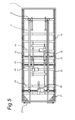
- Figs. 1 , 3 , 5 and 6 the mattress base 1 and the support 2 attached thereto are shown in the reversed position, i.e. upside down.
- the support 2 is shown separately in Fig. 2 in the same reversed position and consists of a framework 33 with longitudinal girders 3 and transverse girders 4.
- Each of these transverse girders consists of the outer tube 5 and inner tube 6 which can be extended and retracted inside each other in a telescopic manner.
- the sleeve 34 which is preferably made from plastic material, is provided in the outer tube 5.
- This sleeve also assists the displacement of the outer tube 5 and the inner tube 6 with respect to one another in a suitable manner.
- the fitting 7 is attached to the outer tubes 5.
- a fitting 8 is attached to the longitudinal girders 3.
- the longitudinal girders 3 of the framework 33 are attached to the mattress base.
- the stays 9 which are supported on the floor during normal use are attached to the ends of the longitudinal girders 3. The normal position of use of the mattress base 1 with support 2 is illustrated in Fig. 4 .
- the mattress base consists of a frame 10, a wire mesh 11 comprising interhooking helical springs 12 stretched in the frame 10 and a filling or box spring 13 which is attached to the frame 10 and is supported by the wire mesh 11.
- the mattress base is furthermore divided into a fixed mattress base part 18 and the mattress base parts 19, 20 hingedly attached thereto.
- the mattress base part 21 is hingedly attached to the hinged mattress base part 20 and is situated at the level of the head of a person.
- the frame 10 in turn consists of the fixed frame part 14 and the frame parts 15, 16 which are hingedly connected thereto and form part of the mattress base parts 18, 19 and 20, respectively.
- the frame part 17 is also hingedly attached to the frame part 16 and forms part of the further hinged mattress base part 21.
- a mattress (not shown) can be arranged on the mattress base on which the person ultimately rests.
- the frame 10 furthermore consists of longitudinal profiled sections 22, each of which in turn consists of a corresponding fixed longitudinal profiled section part and movable longitudinal profiled section parts, transverse profiled sections 23 at the ends of the longitudinal profiled sections 22, as well as traverse girders 24, 25.
- the traverse girders 24 form part of the fixed frame parts 14 and are attached to the fittings 8 of the longitudinal profiled sections 3 of the support 2 by means of bolts 32.
- the other traverse girders 25 form part of the movable frame parts 15-17.
- fastening members 36 are welded onto the fixed traverse girders 24 at the correct distance with respect to the lateral side of the frame 10 as determined by the longitudinal profiled sections 22 thereof.
- the transverse profiled sections 4 of the framework 33 of the support 2 are extended so far that the predrilled holes 26 in the opposite fittings 8 are at the same mutual distance as the opposite fastening members 36 on the fixed traverse girders 24.
- the bolts 32 optionally with nuts, the support 2 remains fixed in this extended position.
- the stays 9 are then at the desired mutual distance and the desired distance to the lateral side of the frame 10.
- Figs. 5 and 6 This is also illustrated in Figs. 5 and 6 .
- a relatively narrow mattress base 1 is used.
- the holes in the fixed traverse girders 24 have a predetermined distance to the lateral side of the frame 10.
- the longitudinal profiled sections 3 of the support 2 therefore have to be moved towards one another until they are relatively close to one another, following which the support 2 can be fitted to the mattress base.
- Fig. 6 shows a relatively wide mattress base 1.
- the longitudinal girders 3 of the support 2 now have to be pushed apart over a fairly large distance in order to ensure that the holes 26 in the fittings 8 thereof are at the same mutual distance as the mutual distance of the holes in the fixed traverse girders 24.
- the drive elements 35 are attached to the transverse profiled sections 4 of the support 2, in particular to the fittings 7 thereof. Furthermore, these drive elements 35 are attached to the movable mattress base parts 19 and 20, as is also illustrated in Fig. 7 . A drive element 35 is also fitted between the movable mattress parts 20 and 21. By operating these drive elements 35 in a suitable manner, the mattress base 1 can be moved into various modified positions.
- each extension 27 comprises a leg 28 which can be displaced in a guide 29 which is defined by the stay 9 and the longitudinal profiled section 3. Furthermore, each extension 27 comprises a vertical stay 29. A headboard 30 can be pushed onto these stays 29, in particular on the mounting 31 thereof which is indicated by dashed lines. These extensions 27 can be pushed into the stays 9 and longitudinal profiled sections 3 to a greater or lesser degree.
- a relatively long mattress base is illustrated. In this case, the extensions are pushed in less far, so that the headboard 30 can be fitted to the end of the mattress base.
- a relatively short mattress base is used, in which case the extensions 27 have to be pushed in further in order to be able to fit the headboard at the correct position.
Landscapes
- Mattresses And Other Support Structures For Chairs And Beds (AREA)
Applications Claiming Priority (1)
| Application Number | Priority Date | Filing Date | Title |
|---|---|---|---|
| NL2002425A NL2002425C2 (nl) | 2009-01-19 | 2009-01-19 | Werkwijze voor het vervaardigen van een ondermatras met voet. |
Publications (1)
| Publication Number | Publication Date |
|---|---|
| EP2208443A1 true EP2208443A1 (de) | 2010-07-21 |
Family
ID=40886865
Family Applications (1)
| Application Number | Title | Priority Date | Filing Date |
|---|---|---|---|
| EP10151040A Withdrawn EP2208443A1 (de) | 2009-01-19 | 2010-01-19 | Verfahren zur Herstellung von einem Matratzenboden mit einem Träger |
Country Status (2)
| Country | Link |
|---|---|
| EP (1) | EP2208443A1 (de) |
| NL (1) | NL2002425C2 (de) |
Cited By (2)
| Publication number | Priority date | Publication date | Assignee | Title |
|---|---|---|---|---|
| US9009888B1 (en) * | 2010-04-13 | 2015-04-21 | Med-Mizer, Inc. | Health care bed with variably sized bed frame and method of use thereof |
| CN106954973A (zh) * | 2016-01-08 | 2017-07-18 | 麒盛科技股份有限公司 | 一种电动床床架 |
Citations (5)
| Publication number | Priority date | Publication date | Assignee | Title |
|---|---|---|---|---|
| FR2525450A1 (fr) * | 1982-04-23 | 1983-10-28 | Ida France | Mecanisme de lit |
| US5687437A (en) * | 1994-02-08 | 1997-11-18 | Goldsmith; Aaron | Modular high-low adjustable bed bases retrofitted within the volumes of, and cooperatively operative with, diverse existing contour-adjustable beds so as to create high-low adjustable contour-adjustable beds |
| BE1013033A3 (nl) * | 1999-03-22 | 2001-08-07 | Imhold Nv | Bedonderstel. |
| EP1774873A1 (de) * | 2005-10-14 | 2007-04-18 | Somieres Mecanizados Gaitan, S.A. | Verlängerbares Bett |
| US20080168602A1 (en) * | 2007-01-12 | 2008-07-17 | Diforio Carl J | Bed frame support |
-
2009
- 2009-01-19 NL NL2002425A patent/NL2002425C2/nl not_active IP Right Cessation
-
2010
- 2010-01-19 EP EP10151040A patent/EP2208443A1/de not_active Withdrawn
Patent Citations (5)
| Publication number | Priority date | Publication date | Assignee | Title |
|---|---|---|---|---|
| FR2525450A1 (fr) * | 1982-04-23 | 1983-10-28 | Ida France | Mecanisme de lit |
| US5687437A (en) * | 1994-02-08 | 1997-11-18 | Goldsmith; Aaron | Modular high-low adjustable bed bases retrofitted within the volumes of, and cooperatively operative with, diverse existing contour-adjustable beds so as to create high-low adjustable contour-adjustable beds |
| BE1013033A3 (nl) * | 1999-03-22 | 2001-08-07 | Imhold Nv | Bedonderstel. |
| EP1774873A1 (de) * | 2005-10-14 | 2007-04-18 | Somieres Mecanizados Gaitan, S.A. | Verlängerbares Bett |
| US20080168602A1 (en) * | 2007-01-12 | 2008-07-17 | Diforio Carl J | Bed frame support |
Cited By (3)
| Publication number | Priority date | Publication date | Assignee | Title |
|---|---|---|---|---|
| US9009888B1 (en) * | 2010-04-13 | 2015-04-21 | Med-Mizer, Inc. | Health care bed with variably sized bed frame and method of use thereof |
| US9387140B2 (en) | 2010-04-13 | 2016-07-12 | Med-Mizer, Inc. | Health care bed with variable width bed frame and method for use thereof |
| CN106954973A (zh) * | 2016-01-08 | 2017-07-18 | 麒盛科技股份有限公司 | 一种电动床床架 |
Also Published As
| Publication number | Publication date |
|---|---|
| NL2002425C2 (nl) | 2010-07-20 |
Similar Documents
| Publication | Publication Date | Title |
|---|---|---|
| US5615431A (en) | Bed framework which is adjustable in elevation | |
| US20100138994A1 (en) | Mattress supporting system with headboard attachment | |
| WO2016058869A1 (de) | Elektromotorisch verstellbare stützeinrichtung | |
| US20180000253A1 (en) | Motorized mechanism and motorized furniture | |
| JP2900252B2 (ja) | ソフアーベツド | |
| US4886250A (en) | Spring structure for cushion seating | |
| KR102112591B1 (ko) | 전동침대 프레임 | |
| CN113475898B (zh) | 一种机械伸展装置 | |
| US12557913B2 (en) | Bedstead | |
| ITVE20040012U1 (it) | Staffa di sostegno per bracciolo o schienale di sedie, in particolare sedie da ufficio. | |
| US4754505A (en) | Foldable mattress support with supplemental back spring | |
| DE602005004111T2 (de) | Trägerstruktur für einen Sitz mit einer Tischfunktion und entsprechende Sitzfederungsanordnung | |
| US5305479A (en) | Sofa sleeper having sinuous spring reinforced shoulder area | |
| NL2002425C2 (nl) | Werkwijze voor het vervaardigen van een ondermatras met voet. | |
| KR102112593B1 (ko) | 전동침대 프레임 | |
| US4494258A (en) | Sofa bed mechanism | |
| EP1774873A1 (de) | Verlängerbares Bett | |
| FR2830438A1 (fr) | Lit medicalise allongeable | |
| DE3902334A1 (de) | Bett mit einem zumindest in der neigung verstellbaren liegeelement | |
| KR102855432B1 (ko) | 기능성 소파겸용 침대 | |
| GB2402616A (en) | A bed convertible between a bunk bed and a convertible bed | |
| KR102925849B1 (ko) | 좌방석 가변형 소파 | |
| KR200434975Y1 (ko) | 안전난간을 구비한 침대 | |
| JPH0142614Y2 (de) | ||
| KR0134006Y1 (ko) | 침대용 브라켓 |
Legal Events
| Date | Code | Title | Description |
|---|---|---|---|
| PUAI | Public reference made under article 153(3) epc to a published international application that has entered the european phase |
Free format text: ORIGINAL CODE: 0009012 |
|
| AK | Designated contracting states |
Kind code of ref document: A1 Designated state(s): AT BE BG CH CY CZ DE DK EE ES FI FR GB GR HR HU IE IS IT LI LT LU LV MC MK MT NL NO PL PT RO SE SI SK SM TR |
|
| AX | Request for extension of the european patent |
Extension state: AL BA RS |
|
| STAA | Information on the status of an ep patent application or granted ep patent |
Free format text: STATUS: THE APPLICATION IS DEEMED TO BE WITHDRAWN |
|
| 18D | Application deemed to be withdrawn |
Effective date: 20110122 |