EP2208447A2 - Coulisseau pour rails de voilage - Google Patents
Coulisseau pour rails de voilage Download PDFInfo
- Publication number
- EP2208447A2 EP2208447A2 EP10150294A EP10150294A EP2208447A2 EP 2208447 A2 EP2208447 A2 EP 2208447A2 EP 10150294 A EP10150294 A EP 10150294A EP 10150294 A EP10150294 A EP 10150294A EP 2208447 A2 EP2208447 A2 EP 2208447A2
- Authority
- EP
- European Patent Office
- Prior art keywords
- guide
- slider
- legs
- neck
- spacer
- Prior art date
- Legal status (The legal status is an assumption and is not a legal conclusion. Google has not performed a legal analysis and makes no representation as to the accuracy of the status listed.)
- Withdrawn
Links
Images




Classifications
-
- A—HUMAN NECESSITIES
- A47—FURNITURE; DOMESTIC ARTICLES OR APPLIANCES; COFFEE MILLS; SPICE MILLS; SUCTION CLEANERS IN GENERAL
- A47H—FURNISHINGS FOR WINDOWS OR DOORS
- A47H15/00—Runners or gliders for supporting curtains on rails or rods
- A47H15/04—Gliders
-
- A—HUMAN NECESSITIES
- A47—FURNITURE; DOMESTIC ARTICLES OR APPLIANCES; COFFEE MILLS; SPICE MILLS; SUCTION CLEANERS IN GENERAL
- A47H—FURNISHINGS FOR WINDOWS OR DOORS
- A47H1/00—Curtain suspension devices
- A47H1/04—Curtain rails
- A47H2001/042—Curtain rails shaped as curtain rods
Definitions
- the invention relates to a slider for hanging curtains or the like on a curtain rail, designed with a hook, eye or the like fastener for attachment to a curtain and with two mutually extending at a distance guide legs for guiding the slider in a guide groove of the curtain rail.
- the curtain rail has a flanked by two guide legs guide.
- the guide legs form undercuts and form a rearward of the guide groove arranged space.
- the free-space facing sides of the guide legs form sliding surfaces on which sliding edges the sliding head of the slider can be performed.
- the sliding heads are formed by arranged at the end of the guide legs, facing away from each other protrusions.
- the guide legs close directly to the ends of the eyelet formed by a bow.
- the arc portion of the eyelet forms together with a protruding from the back of one of the guide legs spring tongue, which is tensioned when the two guide legs moved towards each other or are displaced in the direction of extension of the bottom surface of the guide space when turning the slider in a guide groove.
- the sliding heads have a longitudinal extent which is greater than the opening width of the guide groove, so that the slider can be used in the two different angular positions as a carrier for a curtain.
- the diagonal distance of the outer edges of the neck decreases due to the relative movement of the two guide legs when turning the slider to the extent of the opening width.
- the DE 42 00 483 C2 discloses a slider having an eyelet formed by a bow, wherein the two bow ends are each connected to guide legs, each forming a guide clearance.
- sliders which have a circular cross-section having a neck whose diameter is smaller than the opening width of the groove.
- the sliding flanks are formed in this also suitable for use in 6-mm grooves sliders of sections of a rectangular sliding plate, which lies completely in the rear of the guide groove extending space of the curtain rail.
- the sliding plate has a longitudinal extent that is greater than the opening width, but only slightly smaller than the transverse extent of the free space.
- the width of the sliding plate is less than the opening width.
- the width and length of the guide plate are coordinated so that the diagonal is greater than the width of the free space. The plate can be rotated within the free space, whereby due to an elastic deformation, the dimension of the diagonal can decrease.
- the sliding plate In a rotated position by 90 °, the sliding plate can escape through the guide groove from the free space.
- the thus formed slider can thus be used by a plug-and-turn movement at any location in the curtain rail, slide when turning the slider, the diagonally opposite corner regions of the sliding plate to form a detent force on the inner walls of the back of the guide groove clearance of the curtain rail , It is considered disadvantageous in this known slider that it can only be used on such curtain rails whose free space has an adapted distance from the wall.
- the invention has the object of developing the aforementioned slider such that it can be used in a simple manner at any point in a curtain rail, and this should be possible for a wide range of rail profiles.
- the guide legs are connected at least at one of its two ends with a spacer web of the same material and elastically bendable each other.
- the two sliding heads can be connected to one another with a web.
- the material uniform the two sliding heads interconnecting web forms a spring element. This can possibly be deformed by bending or shearing.
- the web limits the Auftechnology the sliding heads and keeps them at least in the area at its maximum distance from the eyelet at a substantially constant distance.
- the longitudinal extension of the sliding heads is smaller than the opening width of the guide groove and corresponds essentially to the extent of the neck width. The latter is typically 6 mm.
- the connecting web thus has the task of keeping the sliding flanks at a distance.
- the range of the smallest reduction of the diagonal distance is thus in the region of the sliding edges. This increases the reliability of the slider.
- the adjacent edges of the arc of the guide clearance are preferably formed by spacer legs and extend on a curved line.
- the length of the spacer legs is preferably greater than the opening width of the guide groove, so that they act as stops when the guide legs are inserted into the guide groove.
- hooks or brackets can be hung in order to attach the glides to a curtain or on a curtain tape.
- measured width of the connecting web is less than its length and is about half to one third of the neck width.
- the material thickness of the connecting web is less than the material thickness of the neck. It can be manufactured according to this design procedure also gliders with a neck width or with a ground clearance of about 4 mm.
- the eyelet is closed by two interconnected spacer legs. These spacer legs each form a flank of the flanked guide clearance.
- the guide legs can protrude freely in this, the shape of a rounded, rectangular or square plate having the spacer leg forming portions of the slider.
- the guide legs can also be connected to one another at the end with a web. Between the two guide legs then extends a distance space which is flanked by the two mutually facing backs of the guide leg. The distance space is also closed by an intermediate portion of the two spacer leg forming portion of the slider and the web.
- the two guide legs have the required elasticity in order to be able to be deflected so that the diagonal distance between the outer edges of the neck is reduced when the guide clearance is "screwed in” into the opening of the curtain rail.
- the bridge can span the distance space arcuately. The bridge can extend over the entire neck length.
- the slider shown in the drawings consists of a one-piece plastic part and can be produced by injection molding.
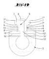
- the slider has an arc section 5, which forms an eyelet.
- the two ends of the loop forming the eyelet 5 each pass into a spacer leg 10. This forms on its side facing away from the sheet 5 a on a curved line extending edge 10 'from.
- a guide leg 6 is formed in each case. This initially forms a neck 11. The outer walls of the neck 11 are spaced apart by the dimension c and form the bottom 9 'of a guide clearance 9. At the direction away from the bow end of the guide leg 6 each sliding heads 7 are formed on the neck 11. Every attachment head 7 forms a sliding edge 7 ', which is the flank 10' of the spacer leg 10 opposite. The sliding flanks 7 'merge into outer edge edges 7 ", which are spaced apart from one another by the dimension e, the neck width b measured transversely to the ground distance c corresponds approximately to the dimension of the arc spacing c.
- the inner peripheral edges of the neck 11 merge into the inner peripheral edges of the sliding head 7, so that the sliding head 7 has a longitudinal extent measured in the extension direction of the spacer legs 10, which corresponds to the neck width b.
- the longitudinal extent of the spacer legs 10 is greater than the longitudinal extent b of the neck 11 and the sliding heads 7.
- a spacing space 12 which defines a distance between the two necks 11 which is greater than the material thickness of the respective neck 11.
- the connecting web 8 thus closes the U-shaped opening formed by the arcuate eyelet 5 and the adjoining guide legs 6 to a closed eye.
- the connecting web 8 forms a stiffening element, in which it prevents further movement of the outermost ends of the two sliding heads 7 toward one another.
- it forms a spring element 8, which deforms elastically when the two guide legs 6 are moved relative to one another.
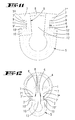
- the connecting web 8 as in the Fig. 11 indicated, bent. But he can also, as in Fig. 8 deliberately exaggerated, sheared.
- the guide legs 6 move against each other such that the diagonal distance d between the outermost edges 11 'of the neck 11, at least in the area near the Distance leg 10 is reduced to the extent of the opening width a of a guide 2 a curtain rail 1.
- the opening width is approx. 6 or approx. 4 mm.
- the material thickness of the connecting web 8 is less than the material thickness of the neck 11.
- the measured in the direction of the longitudinal extent of the sliding head 7 width of the connecting web 8 is less than the longitudinal extension of the sliding head 7, which preferably corresponds to the neck width b.
- the width of the connecting web 8 is about one third to half of the neck width b.
- the length of the connecting web 8, which corresponds to the distance dimension of the spacer space 12, is at least twice as large as the width of the connecting web 8. Based on the elastic properties of the plastic used is the width and the material thickness of the connecting web 8 with respect to its length chosen so that it can perform a sufficient bending or shear, so that the slider can be inserted in the way of a plug-in rotary movement in the guide 2 a curtain rail 1.
- the matching curtain rail 1 has two guide legs 3, which leave a guide groove 2 between them.
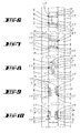
- the design of the back of the guide groove 2 lying space 4 is largely arbitrary. This space 4, for example, according Fig. 1 or according to Fig. 12 be designed.
- the opening width a of the guide groove 2 must be slightly larger than the neck width b or the ground clearance c. However, the opening width a of the guide groove must be slightly smaller than the diagonal distance d between the two outer edges 11 'of the neck 11.
- the opening width a must also be smaller than the diagonal distance d of the outer edges 7 "of the sliding heads 7 , so that the sliding edges 7 'can rest on the guide legs 3.
- the slider described above can in such a curtain rail 1 in the in Fig. 5 and 6 shown rotational position can be used.
- the guide groove has an opening width a of about 6 mm.
- the sliding heads 7 extend transversely to the extension direction of the guide groove 2. If the slider is now rotated by attack on the eyelet 5, the diagonally opposite edges 11 'slide along the mutually facing edges of the guide legs 3. Because of the stiffening effect of the connecting web 8 in the region of the sliding heads 7, the largest reduction of the diagonal distance d takes place in the spacer leg 10 near region of the neck 11. Unless already when turning the slider already the flank 10 'of the spacer leg rests against the guide leg 3, causes the different degrees of deformation or locally different diagonal distance reduction a slide up of the slider in the in Fig. 5 shown position.
- the removal of the slider 1 from the curtain rail 1 is also done by a 90 ° rotation.
- the connecting web 8 is straight in the non-loaded state and is bent or sheared only in its action as a return spring, has the connecting web 8 in the in the Fig. 13 illustrated second embodiment, a slight curvature to the outside. This curvature reduces the stiffening effect of the connecting web 8. According to this curvature can in the in the Fig. 13 shown slider to move the extreme ends of the guide legs 6 to each other. This is associated with an increase in the curvature of the connecting web 8.
- the Indian Fig. 14 shown slider 1 is designed to be used in a guide groove 2 of a curtain rail can, whose opening width is 4 mm. Accordingly closely the two guide legs 6 are adjacent to each other.
- the connecting web 8 may be formed as a stiffening web.
- the connecting web 8 has an outwardly directed curvature, so that the two sliding heads 7 can also move toward one another during rotation of the slider.
- the two spacer legs 10 are connected to each other at a mean distance 10 ".
- Fig. 13 good to recognize, rectangular body formed in the form of a small plate.
- the eyelet 5 which may also be formed as a hook, and on the other side the two spaced apart guide leg 6 from.
- a distance space 12 extends between the two guide legs 6.
- the two guide legs also form a guide clearance 9 here, which is flanked by two flanks 7 ', 10'.
- the guide flank 10 'facing the eyelet 5 is formed by the rectangular section 10.
- the edge of this 10 'opposite Flank 7 ' is formed by a sliding head 7.
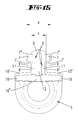
- the two free ends of the two sliding heads 7 are connected to a web 8 with each other.
- the web 8 extends arcuately over the distance space 12 and extends - as from the FIGS. 16 and 17 it can be seen - over the entire neck width b.
- the one-piece slider is made of such a material that the guide clearances can move towards each other.
- the guide legs 6 thus have sufficient elasticity that the diagonal dimension d can be reduced by deformation such that it is smaller than the distance a of the two edges of the guide groove 2 Fig. 15 -17 shown slider can thus in the in the Fig. 6-10 shown manner are screwed into a guide groove 2 of a curtain rail. In this case, essentially a deflection of the guide legs 6 takes place toward each other.
- the extending over the entire neck width web 8 and the connection of the two guide legs 6 via the intermediate portion 10 "prevents shearing.
- the flanks 10 ' may extend slightly inclined roof-like to the distance space 12. Also in a transverse direction to the flanks and the intermediate portion may have a slope.
- the intermediate sections 10 "preferably have the same material thickness as the flanks 10 'in the region of the guide legs 6.
- the object of the in the 15 to 17 embodiment shown also has wedge-shaped mutually tapered flanks 7 ', which are associated with the head 7. These flanks 7 'are approximately half the length of the spacer space 12.
- the spacer space 12 forms a bending escape space for the guide legs 6, since the guide legs 6 on the one hand around the connecting web 8 and on the other hand around its root area, where the flanks 10', can bend.
- the guide legs (6) form mounting legs, with which the slider is mounted in the guide groove 2.
Landscapes
- Curtains And Furnishings For Windows Or Doors (AREA)
Applications Claiming Priority (2)
| Application Number | Priority Date | Filing Date | Title |
|---|---|---|---|
| DE102009003349 | 2009-01-14 | ||
| DE102009025771A DE102009025771A1 (de) | 2009-01-14 | 2009-05-08 | Gleiter für Gardinenschienen |
Publications (2)
| Publication Number | Publication Date |
|---|---|
| EP2208447A2 true EP2208447A2 (fr) | 2010-07-21 |
| EP2208447A3 EP2208447A3 (fr) | 2011-08-10 |
Family
ID=41667966
Family Applications (1)
| Application Number | Title | Priority Date | Filing Date |
|---|---|---|---|
| EP10150294A Withdrawn EP2208447A3 (fr) | 2009-01-14 | 2010-01-08 | Coulisseau pour rails de voilage |
Country Status (2)
| Country | Link |
|---|---|
| EP (1) | EP2208447A3 (fr) |
| DE (1) | DE202009012514U1 (fr) |
Families Citing this family (1)
| Publication number | Priority date | Publication date | Assignee | Title |
|---|---|---|---|---|
| DE102010021773A1 (de) * | 2010-05-27 | 2011-12-01 | Mhz Hachtel Gmbh & Co. Kg | Gardinengleiter |
Citations (3)
| Publication number | Priority date | Publication date | Assignee | Title |
|---|---|---|---|---|
| CH657511A5 (en) | 1984-04-18 | 1986-09-15 | Hanspeter Mueller | Device for hanging a sliding curtain comprising a fixed rail and runners |
| DE4200483C2 (de) | 1992-01-10 | 1993-12-23 | Gerhard Baxmeier | Gleiter für Gardinenschienen |
| DE9301040U1 (de) | 1993-01-27 | 1994-06-01 | Nodeko GmbH Handels- und Vertriebsgesellschaft, 59872 Meschede | Gleiter |
Family Cites Families (1)
| Publication number | Priority date | Publication date | Assignee | Title |
|---|---|---|---|---|
| NL9200489A (nl) * | 1992-03-16 | 1993-10-18 | Bosgoed Groothandel B V | Gordijnophangstelsel, herinpasbaar gordijnophangorgaan, rail geschikt voor het stelsel en werkwijze voor het buigen van de rail. |
-
2009
- 2009-05-08 DE DE202009012514U patent/DE202009012514U1/de not_active Expired - Lifetime
-
2010
- 2010-01-08 EP EP10150294A patent/EP2208447A3/fr not_active Withdrawn
Patent Citations (3)
| Publication number | Priority date | Publication date | Assignee | Title |
|---|---|---|---|---|
| CH657511A5 (en) | 1984-04-18 | 1986-09-15 | Hanspeter Mueller | Device for hanging a sliding curtain comprising a fixed rail and runners |
| DE4200483C2 (de) | 1992-01-10 | 1993-12-23 | Gerhard Baxmeier | Gleiter für Gardinenschienen |
| DE9301040U1 (de) | 1993-01-27 | 1994-06-01 | Nodeko GmbH Handels- und Vertriebsgesellschaft, 59872 Meschede | Gleiter |
Also Published As
| Publication number | Publication date |
|---|---|
| EP2208447A3 (fr) | 2011-08-10 |
| DE202009012514U1 (de) | 2010-02-11 |
Similar Documents
| Publication | Publication Date | Title |
|---|---|---|
| EP2459105B1 (fr) | Attache orthodontique auto-ligaturante | |
| EP3201050B1 (fr) | Languette de boucle munie d'une barre de torsion | |
| EP3452734B1 (fr) | Clip servant à fixer un premier élément à un deuxième élément | |
| DE2941008B1 (de) | Gestell | |
| WO2008116817A1 (fr) | Dispositif de fixation et outil de verrouillage d'un élément de fixation | |
| DE202009016230U1 (de) | Haltevorrichtung für Raffrollo-Perlenraffseile | |
| EP3839275B1 (fr) | Pince de maintien d'une fermeture rapide, fermeture rapide ainsi que raccord de composant doté d'une telle fermeture rapide | |
| EP3478975B1 (fr) | Clip doté d'une tête et d'une tige s'étendant le long d'un axe longitudinal à partir de la tête | |
| EP2420685A1 (fr) | Connecteur de raccordement de rainures profilées ainsi qu'agencement doté de ce type de connecteur | |
| DE20204175U1 (de) | Scharnier für Türen, Fenster u.dgl. | |
| DE102009025771A1 (de) | Gleiter für Gardinenschienen | |
| WO2017001226A1 (fr) | Joint d'abaissement | |
| EP2208447A2 (fr) | Coulisseau pour rails de voilage | |
| DE2212894A1 (de) | Rafflamellenjalousie mit trag und wendeschnueren | |
| EP2385200B1 (fr) | Elément de ferrure pour la fixation dans une rainure de ferrure en forme de C | |
| DE202011000977U1 (de) | Befestigungselement für eine Vorhangträgerleiste | |
| CH698346A2 (de) | Schlaufengleiter mit Einfädelschlitz. | |
| DE2625717C2 (de) | Grund- bzw. Verstellplatte | |
| EP1626150B1 (fr) | Dispositif d'étanchéité | |
| DE2015723C3 (de) | Befestigung einer Eckumlenkung für Treibstangen von Treibstangenverschlüssen, insbesondere von Kipp-Schwenkflügel-Beschlägen, für Fenster, Türen o.dgl | |
| DE102008008695A1 (de) | Profilverbinder | |
| EP2543803B1 (fr) | Bielle pour une ferrure de bielle | |
| EP3153891B1 (fr) | Porte comprenant un écarteur réglable en longueur et son procédé de montage | |
| DE202010009367U1 (de) | Pfostenverbinder | |
| DE2420417C3 (de) | Verbindungsvorrichtung für zwei zusammenstoßende, einen Winkel einschließende Hohlprofilstäbe eines Fensters o.dgl |
Legal Events
| Date | Code | Title | Description |
|---|---|---|---|
| PUAI | Public reference made under article 153(3) epc to a published international application that has entered the european phase |
Free format text: ORIGINAL CODE: 0009012 |
|
| AK | Designated contracting states |
Kind code of ref document: A2 Designated state(s): AT BE BG CH CY CZ DE DK EE ES FI FR GB GR HR HU IE IS IT LI LT LU LV MC MK MT NL NO PL PT RO SE SI SK SM TR |
|
| AX | Request for extension of the european patent |
Extension state: AL BA RS |
|
| PUAL | Search report despatched |
Free format text: ORIGINAL CODE: 0009013 |
|
| AK | Designated contracting states |
Kind code of ref document: A3 Designated state(s): AT BE BG CH CY CZ DE DK EE ES FI FR GB GR HR HU IE IS IT LI LT LU LV MC MK MT NL NO PL PT RO SE SI SK SM TR |
|
| AX | Request for extension of the european patent |
Extension state: AL BA RS |
|
| RIC1 | Information provided on ipc code assigned before grant |
Ipc: A47H 15/04 20060101AFI20110701BHEP |
|
| STAA | Information on the status of an ep patent application or granted ep patent |
Free format text: STATUS: THE APPLICATION IS DEEMED TO BE WITHDRAWN |
|
| 18D | Application deemed to be withdrawn |
Effective date: 20120211 |