EP2208568A1 - Vorrichtung und Verfahren zur Verarbeitung von Material mittels Laser - Google Patents
Vorrichtung und Verfahren zur Verarbeitung von Material mittels Laser Download PDFInfo
- Publication number
- EP2208568A1 EP2208568A1 EP09405013A EP09405013A EP2208568A1 EP 2208568 A1 EP2208568 A1 EP 2208568A1 EP 09405013 A EP09405013 A EP 09405013A EP 09405013 A EP09405013 A EP 09405013A EP 2208568 A1 EP2208568 A1 EP 2208568A1
- Authority
- EP
- European Patent Office
- Prior art keywords
- laser
- laser beam
- liquid jet
- nozzle
- jet
- Prior art date
- Legal status (The legal status is an assumption and is not a legal conclusion. Google has not performed a legal analysis and makes no representation as to the accuracy of the status listed.)
- Withdrawn
Links
- 239000000463 material Substances 0.000 title claims abstract description 25
- 238000000034 method Methods 0.000 title claims abstract description 17
- 239000007788 liquid Substances 0.000 claims abstract description 71
- 230000003287 optical effect Effects 0.000 claims description 16
- 230000001902 propagating effect Effects 0.000 claims description 4
- XLYOFNOQVPJJNP-UHFFFAOYSA-N water Substances O XLYOFNOQVPJJNP-UHFFFAOYSA-N 0.000 description 25
- 239000013307 optical fiber Substances 0.000 description 19
- 238000010168 coupling process Methods 0.000 description 11
- 230000008878 coupling Effects 0.000 description 10
- 238000005859 coupling reaction Methods 0.000 description 10
- 238000005516 engineering process Methods 0.000 description 4
- 239000000835 fiber Substances 0.000 description 3
- 230000015572 biosynthetic process Effects 0.000 description 2
- 230000003111 delayed effect Effects 0.000 description 2
- 230000036278 prepulse Effects 0.000 description 2
- 238000002310 reflectometry Methods 0.000 description 2
- 238000010521 absorption reaction Methods 0.000 description 1
- 239000002826 coolant Substances 0.000 description 1
- 230000000694 effects Effects 0.000 description 1
- 238000005286 illumination Methods 0.000 description 1
- 238000003754 machining Methods 0.000 description 1
- 230000003019 stabilising effect Effects 0.000 description 1
- 238000002834 transmittance Methods 0.000 description 1
Images

Classifications
-
- B—PERFORMING OPERATIONS; TRANSPORTING
- B23—MACHINE TOOLS; METAL-WORKING NOT OTHERWISE PROVIDED FOR
- B23K—SOLDERING OR UNSOLDERING; WELDING; CLADDING OR PLATING BY SOLDERING OR WELDING; CUTTING BY APPLYING HEAT LOCALLY, e.g. FLAME CUTTING; WORKING BY LASER BEAM
- B23K26/00—Working by laser beam, e.g. welding, cutting or boring
- B23K26/02—Positioning or observing the workpiece, e.g. with respect to the point of impact; Aligning, aiming or focusing the laser beam
- B23K26/06—Shaping the laser beam, e.g. by masks or multi-focusing
- B23K26/0604—Shaping the laser beam, e.g. by masks or multi-focusing by a combination of beams
- B23K26/0613—Shaping the laser beam, e.g. by masks or multi-focusing by a combination of beams having a common axis
-
- B—PERFORMING OPERATIONS; TRANSPORTING
- B23—MACHINE TOOLS; METAL-WORKING NOT OTHERWISE PROVIDED FOR
- B23K—SOLDERING OR UNSOLDERING; WELDING; CLADDING OR PLATING BY SOLDERING OR WELDING; CUTTING BY APPLYING HEAT LOCALLY, e.g. FLAME CUTTING; WORKING BY LASER BEAM
- B23K26/00—Working by laser beam, e.g. welding, cutting or boring
- B23K26/02—Positioning or observing the workpiece, e.g. with respect to the point of impact; Aligning, aiming or focusing the laser beam
- B23K26/06—Shaping the laser beam, e.g. by masks or multi-focusing
- B23K26/0604—Shaping the laser beam, e.g. by masks or multi-focusing by a combination of beams
-
- B—PERFORMING OPERATIONS; TRANSPORTING
- B23—MACHINE TOOLS; METAL-WORKING NOT OTHERWISE PROVIDED FOR
- B23K—SOLDERING OR UNSOLDERING; WELDING; CLADDING OR PLATING BY SOLDERING OR WELDING; CUTTING BY APPLYING HEAT LOCALLY, e.g. FLAME CUTTING; WORKING BY LASER BEAM
- B23K26/00—Working by laser beam, e.g. welding, cutting or boring
- B23K26/14—Working by laser beam, e.g. welding, cutting or boring using a fluid stream, e.g. a jet of gas, in conjunction with the laser beam; Nozzles therefor
- B23K26/146—Working by laser beam, e.g. welding, cutting or boring using a fluid stream, e.g. a jet of gas, in conjunction with the laser beam; Nozzles therefor the fluid stream containing a liquid
Definitions
- the invention relates to an apparatus for processing material by the means of liquid jet guided laser.
- Said apparatus comprises
- the invention relates to a method for material processing and to a method of aligning said apparatus.
- the main elements of the so called LMJ® technology consist in a lens system focussing the laser beam, a relatively thin high-pressure water chamber (also called coupling unit) and a nozzle with a small diameter.
- a typical nozzle diameter is 20 to 150 micrometers.
- the water jet serves as a cooling medium for the machined part of the work piece and removes in a very efficient way the ablated material, leading to very good machining quality.
- the solution of the problem is achieved according to the claim 1 by an apparatus comprising at least two laser beam entries and a beam combiner for superposing two laser beams entering through the at least two laser beam entries to a superposed laser beam. Said superposed laser beam is fed into the focussing unit and therefore coupled into the liquid jet.
- the two beams are exactly overlapping in space or in time, but that the two beams are coupled into the liquid jet.
- the method for material processing according to the invention uses laser beams guided in a liquid jet whereas at least two laser beams are coupled into the liquid jet.
- the invention comprises a method for aligning said apparatus whereas a beam combining element is used to combine at least two laser beams to form a combined laser beam, a lens system is used for focusing the superposed laser beams into the liquid jet and a light source and an observation tool is used to align the laser beams.
- the method comprises the following steps:
- the method could comprise the following steps: a) a first laser beam is switch on and focused into the liquid jet and b) a second laser beam is switched on and focused into the liquid jet.
- the material processing can be improved because different lasers can take part in different tasks of the material processing. These tasks can be done either simultaneously or temporally delayed.
- a laser pulse of the first laser can be used as a pre-pulse for a laser pulse of the second laser.
- the beam combiner does not have to overlap both beams exactly in space. Once they are coupled into the liquid jet, the two laser beams fill out the whole cross section of the liquid jet and therefore working spots of the two lasers are exactly the same. This is in opposite to direct laser processing with two lasers, where a beam combiner has to combine the laser beams exactly in space or more than one working spot of the lasers will be the result.
- the apparatus comprises all the advantages of the liquid jet guided laser technology.
- each of the laser beam entries defines a beam path with an optical axis that is parallel to a jet axis of the liquid jet.
- the optical axis of at least one of the laser beam entries can be at an angle, in particular orthogonal, to the optical axis of the other laser beam and therefore also at an angle with respect to the jet axis. This might reduce the number of optical mirrors in the apparatus. Generally speaking, it is not mandatory that each one of the laser beam entries is parallel to the jet axis of the liquid jet.
- the optical axis of one of the laser beam entries is on the axis of the liquid jet. This has the advantage of limiting the use of guiding optics, especially tilted mirrors to guide the laser to the focussing unit for focussing the laser through the entry window into the nozzle.
- none of the optical axis of the laser beam entries is on the axis of the liquid jet.
- the beam combiner comprises a tilted mirror, which is transparent for a first laser beam propagating in a first of the beam paths and reflecting for a second laser beam propagating in a second of the beam paths.
- a tilted mirror with a selective characteristic in respect to laser light is a simple way to superpose two laser beams. In this way the laser beam paths of the different laser beam entries are overlapping after the beam combiner.
- the said tilted mirror might be selective in polarisation, i. e. the mirror might be high reflective for examples for s-polarised light and high transparent for p-polarised light.
- the said mirror might be a dichroic mirror as well, which is selective concerning the wavelength, i. e. the dichroic mirror has a high reflectivity for one wavelength and a high transmittance for another wavelength under a certain angle of incidence, particularly under an angle of incidence of 45°.
- beam combiner based on the different type of beam splitters are possible.
- a beam combiner could comprise a rotating mirror which alternatively reflects the first and the second laser beam onto the focussing unit.
- More laser beams can be combined by one or more beam combiner.
- the different laser beam entry might be positioned star like around the beam combiner, as well.
- the apparatus comprises two additional tilted mirrors arranged after said beam combiner for introducing the superposed laser beams into the focussing unit.
- the two tilted mirrors provide a simple means for aligning the superposed laser beam into the focussing unit.
- the superposed laser beam after passing the beam combiner can propagate along the jet axis.
- tilted mirrors are used before the beam combiner or the laser beam entries comprise a mechanism, in particular translation and tilting means, for aligning the laser beams.
- the apparatus comprises a camera which is arranged parallel to the optical axis of the laser beam entries. Said camera supervises the coupling in of the superposed laser beams into the liquid jet. This enables a direct view on the coupling process, where the focussing of the laser beams into the entrance of the nozzle can be supervised. Therefore a real-time adjusting system is provided.
- the camera can be placed at different places, in particular behind any of the tilted mirrors. Further it is imaginable as well that the alignment is done in a different way.
- the apparatus comprises a light source which is arranged along the jet axis of the liquid jet.
- the light source can be placed around the second beam entry.
- the light source can be place behind the second tilted mirror. Placing a light source close to the jet axis has the advantage of illuminating the jet axis as well as an entrance of the nozzle, thus helping the observation by the camera of coupling the laser beam into liquid jet.
- the light source for illumination the entrance of the nozzle can be omitted.
- different positions of the light source are imaginable.
- the light source might be placed in such a way that the beam combiner is illuminated as well.
- the light source is placed behind the second additional tilted mirror on the jet axis.
- This has the advantage that the entrance of the nozzle is directly illuminated and back-reflections of the light of the light source from the entrance of the nozzle are reflected into the camera by the second additional tilted mirror.
- the light source is placed around the first laser beam entry which is in line with the jet axis.
- This has the advantage that in the case that two additional tilted mirrors are used after the beam combiner the entrance of the nozzle is also directly illuminated. Back-reflections of the light of the light source from the entrance of the nozzle are reflected into the camera by the beam combiner.
- the apparatus comprises an adjustment mechanics for moving the focussing unit relative to the beam combiner. This allows separating the aligning of the beam combiner for superposing the laser beams and focussing the superposed laser beam into the focusing system.
- the simplest case would be two tilted mirrors after the beam combiner.
- the beam combiner and/or the laser beam entries can comprise an adjustment mechanics for adjusting the superposed laser beam into the focussing system.
- the machine head is provided with a gas application chamber for applying a gas jacket to the liquid jet ejected by the nozzle.
- a gas application chamber for applying a gas jacket to the liquid jet ejected by the nozzle.
- the method comprises two laser beams which are different with respect to wavelength, continuous/pulse mode and/or energy level.
- This has the advantage that different characteristics of the laser sources can be used for material processing. Without realigning the machine different work can be done on the material either at the same time or temporally delayed. For examples if laser in pulsed mode are used, then a pulse of one laser can be used as a pre-pulse for a pulse of the second laser.
- the laser beams can only differ in polarisation or they might be identical.
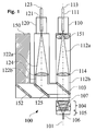
- Figure 1 shows a first apparatus 100 of the apparatus of the invention, where a first laser beam entry 110 is in line with a jet axis 101 of a liquid jet.
- the liquid jet is a water jet 106.
- the first laser beams entry 110 is formed in such a way that a first optical fibre 111 can be connected to it.
- An output beam of e. g. a Nd:YAG laser (not shown), emitting laser light at a wavelength of 1064 nm, is coupled into the optical fibre 111.
- the first laser beam entry 110 has translation and tilting means for adjusting a first laser beam 112a emitted by the first optical fibre 111.
- the first laser beam 112a is adjusted along a first optical axis 113 which is in line with the jet axis 101.
- a first collimating lens 114 collimates the divergent first laser beam 112a of the optical fibre 111 to a first collimated laser beam 112b. After the first collimating lens 114 the first collimated laser beam 112b enters a focussing lens system 104, where the first collimated laser beam 112b is focussed through a coupling unit 105 into the water jet 106.
- the technical details of a machine head comprising the focusing lens system 104 and the coupling unit 105 producing a water jet 106 are known from document US 5,902,499 (Synova ) which is incorporated herein by reference.
- the coupling unit 105 mainly comprises a window (not shown) for the laser beam to enter into a stagnation free water chamber (not shown) and a nozzle (not shown) for producing a water jet 106.
- a laser beam is coupled into the water jet 106 by focussing on an entrance of the nozzle. Further due to the absence of a retaining chamber in an area surrounding the entrance of the nozzle, a sufficiently high flow speed of the liquid in this area makes sure that a formation of a thermal lens in the water is suppressed.
- a beam combiner formed as a tilted dichroic mirror 103, is inserted under an angle of incidence of 45°.
- the dichroic mirror 103 is highly transparent for light at a wavelength of 1064 nm and highly reflecting for light at a wavelength of 532 nm under an angle of incidence of 45°. Mirrors with such features are well known to a person skilled in the art.
- a second laser beam entry 120 in the form of a fibre holder is placed.
- a second optical fibre 121 is connected to the second laser beam entry 120.
- a second output beam of a frequency doubled Nd:YAG laser (not shown) emitting light at a wavelength of 532 nm is coupled into the second optical fibre 121.
- the second laser beam entry 120 has translation and tilting means for adjusting a second laser beam 122a emitted by the second optical fibre 121.
- the second laser beam 122a is adjusted along a second optical axis 123 which is parallel to the liquid jet axis 101.
- a second collimating lens 124 collimates the divergent second laser beam 122a of the second optical fibre 121 to a second collimated laser beam 122b. After the second collimating lens 124 the second collimated laser beam 122b passes a first tilted high reflecting mirror 125, which reflects the second collimated laser beam 122b perpendicular to the liquid jet axis 101 onto the dichroic mirror 103.
- the dichroic mirror 103 is highly reflective for the wavelength of 532 nm the second collimated laser beam 122b is reflected parallel to the jet axis 101, in line with the first collimated laser beam 112b.
- the first and the second collimated laser beam 112b, 122b propagate together as a superposed laser beam 107 towards the coupling unit 106 passing the focussing lens system 104.
- the superposed laser beam 107 is focussed on the entrance of the nozzle 108 and therefore coupled into the water jet 106.
- Figure 3 shows a more detailed drawing of the coupling unit and the nozzle. A detailed description of it, can be found in US 5,902,499 (Synova ), column 6, line 23 to column 8, line 11. It mainly comprises a focussing unit 104, a window 109, a stagnation free water chamber 106a and a nozzle 108. Water flows from a tank (not shown) through the stagnation free water chamber 106a and through the nozzle 108, where a water jet 106 is produced. The focussing unit 104 focus a laser beam through the window 109 onto an entrance of the nozzle 108a.
- a camera 150 for observation is placed next to the second laser beam entry 120, opposite to the first laser beam entry 110. Further the camera 150 is in parallel to the optical axis of the first and second entries 110, 120. Images of the entrance of the nozzle are reflected by the dichroic mirror 103 and a second tilted mirror 152, which is placed behind the first tilted mirror 125, into the camera 150.
- a light source in the form of a ring LED 151 around the first laser beam entry 110 is used to illuminate the entrance of the nozzle.
- the apparatus 100 is aligned with the following steps:
- the first Nd:YAG laser emitting light at 1064 nm is switched on and coupled into the first optical fibre 111, which is connected to the first laser beam entry 110.
- the translation means With the translation means the output of the first optical fibre 111 is positioned on the jet axis 101 whereas with the tilting means the first optical fibre 111 is tilted in such a way that the first output beam 112a is in line with the jet axis 101. Therefore it is focussed by the focussing system 104 onto the entrance of the nozzle 108a and coupled into the water jet 106.
- the second frequency doubled Nd:YAG laser is switched on and coupled into the second optical fibre 121 which is connected to the second laser beam entry 120.
- the second laser beam 122a is adjusted similar to the first laser beam 112a in a such a way that after the beam combiner 103 the second collimated laser beam 122b laser is in line with the first collimated laser beam 112b forming the superposed laser beam 107 which is in line with the liquid jet axis 101. Therefore the second collimated laser beam 122b is coupled into the water jet 106 as well.
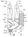
- Figure 2 shows a second embodiment 200 of the invention.
- the arrangement of a first and a second laser beam entries 210, 220, a first and a second optical fibre 211, 221, a first and a second collimated lens 214, 224, a dichroic mirror 203 and a first tilted mirror 225 is the same as in the first embodiment 100, with the exception that a first optical axis 213 of the first laser beam entry 210 is only parallel but not in line with the liquid jet axis 201.
- a first laser beam 212a with a wavelength of 1064 nm is emitted by the first optical fibre 211, collimated as a first collimated laser beam 212b by the first collimating lens 214.
- the first collimated laser beam 212b passes the dichroic mirror 203.
- a second laser beam 222a with a wavelength of 532 nm is emitted by the second optical fibre 221, collimated as a second collimated laser beam 222b by the second collimating lens 224.
- the second collimated laser beam 222b is reflected by the first tilted mirror 225 onto the dichroic mirror 203, which reflects the second collimated laser beam 222b in line with the first collimated laser beam 212b. Both beams propagate together as superposed laser beams 207.
- the superposed laser beam 207 is reflected by a third and a forth tilted mirror 208, 209 before directed through the focussing lens system 204 and focussed on the entrance of the nozzle.
- a camera 250 for observation is placed next to the first laser beam entry 210. Images of the entrance of the nozzle, which are reflected by the forth tilted mirror 209 and by a fifth tilted mirror 255, which is placed behind the third tilted mirror 208, into the camera 250.
- the Nd:YAG laser emitting at 1064 nm is switched on.
- the output laser beam 212a from the first optical fibre 211 is directed through the collimating lens 224 and the dichroic mirror 203.
- the third and forth tilted mirrors 208, 209 are used to direct the collimated beam 222b through the focussing lens system 204 onto the entrance of the nozzle before it is coupled into the water jet 206.
- a LED 256 illuminates the entrance of the nozzle. Therefore the adjustement of the collimated laser beam 212b is observed by the camera 250.
- the second frequency doubled Nd:YAG laser emitting laser light at a wavelength of 532 nm is switched on and coupled into the second optical fibre 223.
- the second laser beam 222a is directed trough the second collimated lens 224, reflected by the first tilted mirror 225 and the dichroic mirror 203.
- the second collimated laser beam 222b is in line with the first collimated laser beam 212b. Therefore the second collimated laser beam 222b is coupled into the water jet 206 as well.
- the embodiments show the superposition of two laser beams, which are coupled into the water jet, the superposition of more than two laser beams are conceivable.
- the method to combine more than two laser beams depends on the used laser sources. For example it is imaginable that twice two laser beams with different wavelength are combined together with a dichroic mirror and that afterwards the two combined beams are superposed by a polarisation depending mirror. Once all laser beams are combined together, they are focused on the entrance of the nozzle and therefore coupled into the liquid jet.
- the different laser beams do not need to overlap after the beam combiner, it is imaginable that more than one focussing system for focusing the laser beam onto the entrance of the nozzle is used.
- the laser beam was delivered from the laser source to the laser beam entry by an optical fibre, it is possible that the laser source is directly placed at the laser beam entry or delivered there by tilted mirrors.
- a dichroic mirror is theoretically 100% reflecting for one wavelength and 100% transparent for the other wavelength, in reality this is not exactly true. Of each wavelength there is always a part of the light, which is passing the dichroic mirror and reflected by the dichroic mirror, respectively. This is true for a normal, high reflecting and tilted mirror as well. Therefore an image of the entrance of the nozzle can be observed by the camera placed behind a tilted mirror.
- the dichroic mirror is high reflecting the wavelength of 532 nm and high transparent for the wavelength at 1064 nm. Dichroic mirror with different reflectivity and transparency at different wavelength are possible according to the different lasers which are used. It is not mandatory that the dichroic mirror is highly reflecting at the SHG, where it is highly transparent. There are dichroic mirrors with well defined ranges, where they are highly reflecting and highly transparent, respectively.
- any liquid for producing the liquid jet is possible as long as the absorption coefficient of the liquid concerning the used wavelengths is small enough that together with a sufficiently high flow speed of the liquid in an area surrounding the entrance of the nozzle a formation of a thermal lens is suppressed.
Landscapes
- Physics & Mathematics (AREA)
- Optics & Photonics (AREA)
- Engineering & Computer Science (AREA)
- Plasma & Fusion (AREA)
- Mechanical Engineering (AREA)
- Laser Beam Processing (AREA)
Priority Applications (1)
| Application Number | Priority Date | Filing Date | Title |
|---|---|---|---|
| EP09405013A EP2208568A1 (de) | 2009-01-20 | 2009-01-20 | Vorrichtung und Verfahren zur Verarbeitung von Material mittels Laser |
Applications Claiming Priority (1)
| Application Number | Priority Date | Filing Date | Title |
|---|---|---|---|
| EP09405013A EP2208568A1 (de) | 2009-01-20 | 2009-01-20 | Vorrichtung und Verfahren zur Verarbeitung von Material mittels Laser |
Publications (1)
| Publication Number | Publication Date |
|---|---|
| EP2208568A1 true EP2208568A1 (de) | 2010-07-21 |
Family
ID=40749610
Family Applications (1)
| Application Number | Title | Priority Date | Filing Date |
|---|---|---|---|
| EP09405013A Withdrawn EP2208568A1 (de) | 2009-01-20 | 2009-01-20 | Vorrichtung und Verfahren zur Verarbeitung von Material mittels Laser |
Country Status (1)
| Country | Link |
|---|---|
| EP (1) | EP2208568A1 (de) |
Cited By (13)
| Publication number | Priority date | Publication date | Assignee | Title |
|---|---|---|---|---|
| CN107470786A (zh) * | 2017-09-14 | 2017-12-15 | 深圳市牧激科技有限公司 | 多激光头装置 |
| US10240254B2 (en) | 2014-11-07 | 2019-03-26 | Element Six Technologies Limited | Method of fabricating plates of super-hard material using a collimated cutting beam |
| JP2019155480A (ja) * | 2014-06-16 | 2019-09-19 | シノヴァ エスアーSynova Sa | 加工ヘッド |
| CN110719696A (zh) * | 2019-10-22 | 2020-01-21 | 东莞三润田智能科技股份有限公司 | Pcb阻焊开窗方法及pcb激光开窗机 |
| EP3685954A1 (de) * | 2019-01-22 | 2020-07-29 | Synova S.A. | Verfahren und vorrichtung zum schneiden eines werkstücks mit einem komplexen fluidstrahlgeführten laserstrahl |
| CN113423532A (zh) * | 2019-02-13 | 2021-09-21 | 大学共同利用机关法人自然科学研究机构 | 激光加工装置及激光加工方法 |
| CN113618232A (zh) * | 2021-07-28 | 2021-11-09 | 中国科学院宁波材料技术与工程研究所 | 一种双光束耦合水导加工头装置及加工方法 |
| EP4209300A1 (de) * | 2022-01-07 | 2023-07-12 | Raytheon Technologies Corporation | Wasserstrahlgeführte lasermaschine mit optischer inline-rückkopplungsregelung |
| GR1010629B (el) * | 2023-10-20 | 2024-02-07 | Στυλιανος Νικολαου Μορες | Συσκευη και μεθοδος κατεργασιας ενος αγωγιμου υλικου |
| CN119159224A (zh) * | 2024-11-22 | 2024-12-20 | 西安晟光硅研半导体科技有限公司 | 一种微射流激光设备的双波段加工头及其聚焦调控方法 |
| CN119187845A (zh) * | 2024-11-26 | 2024-12-27 | 西安晟光硅研半导体科技有限公司 | 一种聚焦物镜和双波段微射流激光设备的加工头 |
| CN119407322A (zh) * | 2024-11-13 | 2025-02-11 | 北京工业大学 | 一种外层焦点旋转辅助高功率激光复合焊接装置 |
| CN121055135A (zh) * | 2025-11-05 | 2025-12-02 | 上海稀光智能科技有限公司 | 多波长激光同时耦合的水导激光产生装置 |
Citations (6)
| Publication number | Priority date | Publication date | Assignee | Title |
|---|---|---|---|---|
| US4839497A (en) * | 1987-09-03 | 1989-06-13 | Digital Equipment Corporation | Drilling apparatus and method |
| US5258989A (en) | 1990-02-12 | 1993-11-02 | Diomed Limited | Solid state laser diode light source |
| US5902499A (en) | 1994-05-30 | 1999-05-11 | Richerzhagen; Bernold | Method and apparatus for machining material with a liquid-guided laser beam |
| WO1999056907A1 (de) * | 1998-04-30 | 1999-11-11 | Synova S.A. | Materialbearbeitungsvorrichtung mit einem in einen flüssigkeitsstrahl eingekoppelten laserstrahl |
| WO2003059567A1 (de) * | 2002-01-16 | 2003-07-24 | Siemens Aktiengesellschaft | Laserbearbeitungsvorrichtung |
| WO2007013293A1 (ja) * | 2005-07-26 | 2007-02-01 | Shibuya Kogyo Co., Ltd. | ハイブリッドレーザ加工装置 |
-
2009
- 2009-01-20 EP EP09405013A patent/EP2208568A1/de not_active Withdrawn
Patent Citations (6)
| Publication number | Priority date | Publication date | Assignee | Title |
|---|---|---|---|---|
| US4839497A (en) * | 1987-09-03 | 1989-06-13 | Digital Equipment Corporation | Drilling apparatus and method |
| US5258989A (en) | 1990-02-12 | 1993-11-02 | Diomed Limited | Solid state laser diode light source |
| US5902499A (en) | 1994-05-30 | 1999-05-11 | Richerzhagen; Bernold | Method and apparatus for machining material with a liquid-guided laser beam |
| WO1999056907A1 (de) * | 1998-04-30 | 1999-11-11 | Synova S.A. | Materialbearbeitungsvorrichtung mit einem in einen flüssigkeitsstrahl eingekoppelten laserstrahl |
| WO2003059567A1 (de) * | 2002-01-16 | 2003-07-24 | Siemens Aktiengesellschaft | Laserbearbeitungsvorrichtung |
| WO2007013293A1 (ja) * | 2005-07-26 | 2007-02-01 | Shibuya Kogyo Co., Ltd. | ハイブリッドレーザ加工装置 |
Cited By (24)
| Publication number | Priority date | Publication date | Assignee | Title |
|---|---|---|---|---|
| JP2019155480A (ja) * | 2014-06-16 | 2019-09-19 | シノヴァ エスアーSynova Sa | 加工ヘッド |
| US10240254B2 (en) | 2014-11-07 | 2019-03-26 | Element Six Technologies Limited | Method of fabricating plates of super-hard material using a collimated cutting beam |
| CN107470786A (zh) * | 2017-09-14 | 2017-12-15 | 深圳市牧激科技有限公司 | 多激光头装置 |
| EP3685954A1 (de) * | 2019-01-22 | 2020-07-29 | Synova S.A. | Verfahren und vorrichtung zum schneiden eines werkstücks mit einem komplexen fluidstrahlgeführten laserstrahl |
| US12280449B2 (en) | 2019-01-22 | 2025-04-22 | Synova S.A. | Method and apparatus for cutting and ablating a workpiece with a complex fluid-jet-guided laser beam |
| WO2020152136A1 (en) * | 2019-01-22 | 2020-07-30 | Synova S.A. | Method and apparatus for cutting or ablating a workpiece with a complex fluid-jet-guided laser beam |
| CN113329838A (zh) * | 2019-01-22 | 2021-08-31 | 辛诺瓦有限公司 | 利用流体射流引导的复合激光束切割或烧蚀工件的方法和设备 |
| JP2022518241A (ja) * | 2019-01-22 | 2022-03-14 | シノヴァ エスアー | 液体噴流でガイドされた合成レーザービームを用いて被加工材を切断または切除する方法および装置 |
| KR102690774B1 (ko) * | 2019-01-22 | 2024-08-05 | 시노바 에스.에이 | 복합 유체 제트 가이드 레이저 빔을 사용하여 공작물을 컷팅하거나 어블레이팅하는 방법 및 장치 |
| CN113423532A (zh) * | 2019-02-13 | 2021-09-21 | 大学共同利用机关法人自然科学研究机构 | 激光加工装置及激光加工方法 |
| CN113423532B (zh) * | 2019-02-13 | 2024-04-02 | 大学共同利用机关法人自然科学研究机构 | 激光加工装置及激光加工方法 |
| CN110719696A (zh) * | 2019-10-22 | 2020-01-21 | 东莞三润田智能科技股份有限公司 | Pcb阻焊开窗方法及pcb激光开窗机 |
| CN113618232A (zh) * | 2021-07-28 | 2021-11-09 | 中国科学院宁波材料技术与工程研究所 | 一种双光束耦合水导加工头装置及加工方法 |
| CN113618232B (zh) * | 2021-07-28 | 2024-03-19 | 中国科学院宁波材料技术与工程研究所 | 一种双光束耦合水导加工头装置及加工方法 |
| EP4209300A1 (de) * | 2022-01-07 | 2023-07-12 | Raytheon Technologies Corporation | Wasserstrahlgeführte lasermaschine mit optischer inline-rückkopplungsregelung |
| US20230219168A1 (en) * | 2022-01-07 | 2023-07-13 | Raytheon Technologies Corporation | Waterjet-guided laser machine with inline optical feedback control |
| GR1010629B (el) * | 2023-10-20 | 2024-02-07 | Στυλιανος Νικολαου Μορες | Συσκευη και μεθοδος κατεργασιας ενος αγωγιμου υλικου |
| CN119407322A (zh) * | 2024-11-13 | 2025-02-11 | 北京工业大学 | 一种外层焦点旋转辅助高功率激光复合焊接装置 |
| CN119159224A (zh) * | 2024-11-22 | 2024-12-20 | 西安晟光硅研半导体科技有限公司 | 一种微射流激光设备的双波段加工头及其聚焦调控方法 |
| CN119159224B (zh) * | 2024-11-22 | 2025-04-25 | 西安晟光硅研半导体科技有限公司 | 一种微射流激光设备的双波段加工头及其聚焦调控方法 |
| WO2026108509A1 (zh) * | 2024-11-22 | 2026-05-28 | 西安晟光硅研半导体科技有限公司 | 一种微射流激光设备的双波段加工头及其聚焦调控方法 |
| CN119187845A (zh) * | 2024-11-26 | 2024-12-27 | 西安晟光硅研半导体科技有限公司 | 一种聚焦物镜和双波段微射流激光设备的加工头 |
| CN119187845B (zh) * | 2024-11-26 | 2025-03-18 | 西安晟光硅研半导体科技有限公司 | 一种聚焦物镜和双波段微射流激光设备的加工头 |
| CN121055135A (zh) * | 2025-11-05 | 2025-12-02 | 上海稀光智能科技有限公司 | 多波长激光同时耦合的水导激光产生装置 |
Similar Documents
| Publication | Publication Date | Title |
|---|---|---|
| US11364572B2 (en) | Laser cutting head with dual movable mirrors providing beam alignment and/or wobbling movement | |
| US7102118B2 (en) | Beam formation unit comprising two axicon lenses, and device comprising one such beam formation unit for introducing radiation energy into a workpiece consisting of a weakly-absorbent material | |
| KR101120471B1 (ko) | 다중 초점 방식의 펄스 레이저를 이용한 취성 재료 절단 장치 | |
| US4123143A (en) | Laser beam aligning apparatus | |
| US20190126395A1 (en) | Laser machining head and laser machining apparatus | |
| US6727462B2 (en) | Laser machining device | |
| TWI457601B (zh) | 偏光方位角調整裝置及雷射加工裝置 | |
| JP7682533B2 (ja) | レーザ処理装置 | |
| CN113305422A (zh) | 一种同轴共焦激光加工系统 | |
| KR20080112691A (ko) | 레이저를 이용한 공작물 가공장치 | |
| US20210394304A1 (en) | Fiber coupled laser with variable beam parameters product | |
| JP7398649B2 (ja) | レーザ加工装置およびレーザ加工方法 | |
| US7088517B2 (en) | Beam splitter device or laser-scanning microscope | |
| JP3595511B2 (ja) | レーザ加工ヘッド及びこれを備えたレーザ加工装置 | |
| JP4690967B2 (ja) | 加工深さを増加したレーザ加工装置 | |
| KR100862522B1 (ko) | 레이저가공 장치 및 기판 절단 방법 | |
| JP2016078073A (ja) | ダイレクトダイオードレーザ光による板金の加工方法及びこれを実行するダイレクトダイオードレーザ加工装置 | |
| JP2000263270A (ja) | レーザ加工装置用光学系 | |
| CN116583376A (zh) | 借助在多芯光纤中引导的激光射束进行激光切割的方法和设备及相关计算机程序产品 | |
| KR101057457B1 (ko) | 드릴링 장치 및 드릴링 방법 | |
| JP2001255491A (ja) | レーザ集光光学系 | |
| JP7411851B1 (ja) | 偏光調整装置及びレーザ加工機 | |
| Ryba et al. | Unique beam delivery and processing tools for high power solid state laser processing | |
| JP7157450B2 (ja) | レーザ加工装置 | |
| JP2000141072A (ja) | 光合成方法及び合成出射光学系 |
Legal Events
| Date | Code | Title | Description |
|---|---|---|---|
| PUAI | Public reference made under article 153(3) epc to a published international application that has entered the european phase |
Free format text: ORIGINAL CODE: 0009012 |
|
| AK | Designated contracting states |
Kind code of ref document: A1 Designated state(s): AT BE BG CH CY CZ DE DK EE ES FI FR GB GR HR HU IE IS IT LI LT LU LV MC MK MT NL NO PL PT RO SE SI SK TR |
|
| AX | Request for extension of the european patent |
Extension state: AL BA RS |
|
| 17P | Request for examination filed |
Effective date: 20110111 |
|
| 17Q | First examination report despatched |
Effective date: 20110202 |
|
| AKX | Designation fees paid |
Designated state(s): CH DE LI |
|
| R17C | First examination report despatched (corrected) |
Effective date: 20110204 |
|
| STAA | Information on the status of an ep patent application or granted ep patent |
Free format text: STATUS: THE APPLICATION IS DEEMED TO BE WITHDRAWN |
|
| 18D | Application deemed to be withdrawn |
Effective date: 20110615 |