EP2208599A1 - Verfahren und gekühlte Vorrichtung zur Abgabe von Polyurethangemischen - Google Patents
Verfahren und gekühlte Vorrichtung zur Abgabe von Polyurethangemischen Download PDFInfo
- Publication number
- EP2208599A1 EP2208599A1 EP10150737A EP10150737A EP2208599A1 EP 2208599 A1 EP2208599 A1 EP 2208599A1 EP 10150737 A EP10150737 A EP 10150737A EP 10150737 A EP10150737 A EP 10150737A EP 2208599 A1 EP2208599 A1 EP 2208599A1
- Authority
- EP
- European Patent Office
- Prior art keywords
- dispensing device
- polyurethane mixture
- meatus
- mixture
- slit
- Prior art date
- Legal status (The legal status is an assumption and is not a legal conclusion. Google has not performed a legal analysis and makes no representation as to the accuracy of the status listed.)
- Withdrawn
Links
- 239000000203 mixture Substances 0.000 title claims abstract description 188
- 229920002635 polyurethane Polymers 0.000 title claims abstract description 116
- 239000004814 polyurethane Substances 0.000 title claims abstract description 116
- 238000000034 method Methods 0.000 title claims description 22
- 239000004088 foaming agent Substances 0.000 claims abstract description 35
- 239000012809 cooling fluid Substances 0.000 claims abstract description 33
- 238000001816 cooling Methods 0.000 claims description 63
- 238000009826 distribution Methods 0.000 claims description 43
- 238000009835 boiling Methods 0.000 claims description 28
- 239000007788 liquid Substances 0.000 claims description 28
- 239000006260 foam Substances 0.000 claims description 27
- 238000006243 chemical reaction Methods 0.000 claims description 23
- 239000012530 fluid Substances 0.000 claims description 16
- 230000015572 biosynthetic process Effects 0.000 claims description 8
- 238000004891 communication Methods 0.000 claims description 8
- 230000003247 decreasing effect Effects 0.000 claims description 2
- 239000007789 gas Substances 0.000 description 30
- 239000000758 substrate Substances 0.000 description 16
- 230000009467 reduction Effects 0.000 description 9
- 238000012360 testing method Methods 0.000 description 9
- 230000008859 change Effects 0.000 description 7
- 238000005187 foaming Methods 0.000 description 7
- 238000010586 diagram Methods 0.000 description 6
- 239000000523 sample Substances 0.000 description 6
- 229920005830 Polyurethane Foam Polymers 0.000 description 5
- 239000000463 material Substances 0.000 description 5
- 239000002184 metal Substances 0.000 description 5
- 239000011496 polyurethane foam Substances 0.000 description 5
- 239000002904 solvent Substances 0.000 description 5
- 238000005406 washing Methods 0.000 description 5
- LYCAIKOWRPUZTN-UHFFFAOYSA-N Ethylene glycol Chemical compound OCCO LYCAIKOWRPUZTN-UHFFFAOYSA-N 0.000 description 4
- 239000003795 chemical substances by application Substances 0.000 description 4
- 238000009472 formulation Methods 0.000 description 4
- 238000004519 manufacturing process Methods 0.000 description 4
- 239000000126 substance Substances 0.000 description 4
- 230000003111 delayed effect Effects 0.000 description 3
- 230000000694 effects Effects 0.000 description 3
- 230000008569 process Effects 0.000 description 3
- 230000002829 reductive effect Effects 0.000 description 3
- XLYOFNOQVPJJNP-UHFFFAOYSA-N water Substances O XLYOFNOQVPJJNP-UHFFFAOYSA-N 0.000 description 3
- 239000000654 additive Substances 0.000 description 2
- 230000033228 biological regulation Effects 0.000 description 2
- 239000003054 catalyst Substances 0.000 description 2
- 230000001276 controlling effect Effects 0.000 description 2
- 230000008021 deposition Effects 0.000 description 2
- 238000011161 development Methods 0.000 description 2
- 230000004907 flux Effects 0.000 description 2
- 238000013012 foaming technology Methods 0.000 description 2
- WGCNASOHLSPBMP-UHFFFAOYSA-N hydroxyacetaldehyde Natural products OCC=O WGCNASOHLSPBMP-UHFFFAOYSA-N 0.000 description 2
- 230000000750 progressive effect Effects 0.000 description 2
- 230000001105 regulatory effect Effects 0.000 description 2
- 229920005989 resin Polymers 0.000 description 2
- 239000011347 resin Substances 0.000 description 2
- 241001311547 Patina Species 0.000 description 1
- 230000005679 Peltier effect Effects 0.000 description 1
- 239000004698 Polyethylene Substances 0.000 description 1
- 229910000831 Steel Inorganic materials 0.000 description 1
- 238000005452 bending Methods 0.000 description 1
- 238000004364 calculation method Methods 0.000 description 1
- 238000004140 cleaning Methods 0.000 description 1
- 230000001010 compromised effect Effects 0.000 description 1
- 238000005094 computer simulation Methods 0.000 description 1
- 239000004020 conductor Substances 0.000 description 1
- 239000006071 cream Substances 0.000 description 1
- 230000007423 decrease Effects 0.000 description 1
- 230000002950 deficient Effects 0.000 description 1
- 230000001934 delay Effects 0.000 description 1
- 230000001804 emulsifying effect Effects 0.000 description 1
- 238000005516 engineering process Methods 0.000 description 1
- 238000010438 heat treatment Methods 0.000 description 1
- 239000011796 hollow space material Substances 0.000 description 1
- 238000003780 insertion Methods 0.000 description 1
- 230000037431 insertion Effects 0.000 description 1
- 239000012948 isocyanate Substances 0.000 description 1
- 150000002513 isocyanates Chemical class 0.000 description 1
- 238000003475 lamination Methods 0.000 description 1
- 230000000670 limiting effect Effects 0.000 description 1
- 238000012423 maintenance Methods 0.000 description 1
- 238000012986 modification Methods 0.000 description 1
- 230000004048 modification Effects 0.000 description 1
- 230000036961 partial effect Effects 0.000 description 1
- 239000002245 particle Substances 0.000 description 1
- 230000000737 periodic effect Effects 0.000 description 1
- 229920003023 plastic Polymers 0.000 description 1
- 239000004033 plastic Substances 0.000 description 1
- -1 polyethylene Polymers 0.000 description 1
- 229920000573 polyethylene Polymers 0.000 description 1
- 238000006116 polymerization reaction Methods 0.000 description 1
- 230000000379 polymerizing effect Effects 0.000 description 1
- 229920005749 polyurethane resin Polymers 0.000 description 1
- 230000002028 premature Effects 0.000 description 1
- 239000000376 reactant Substances 0.000 description 1
- 230000009257 reactivity Effects 0.000 description 1
- 239000007787 solid Substances 0.000 description 1
- 239000010959 steel Substances 0.000 description 1
- 238000013517 stratification Methods 0.000 description 1
- 238000011144 upstream manufacturing Methods 0.000 description 1
Images




Classifications
-
- B—PERFORMING OPERATIONS; TRANSPORTING
- B29—WORKING OF PLASTICS; WORKING OF SUBSTANCES IN A PLASTIC STATE IN GENERAL
- B29C—SHAPING OR JOINING OF PLASTICS; SHAPING OF MATERIAL IN A PLASTIC STATE, NOT OTHERWISE PROVIDED FOR; AFTER-TREATMENT OF THE SHAPED PRODUCTS, e.g. REPAIRING
- B29C44/00—Shaping by internal pressure generated in the material, e.g. swelling or foaming ; Producing porous or cellular expanded plastics articles
- B29C44/34—Auxiliary operations
- B29C44/3415—Heating or cooling
-
- B—PERFORMING OPERATIONS; TRANSPORTING
- B29—WORKING OF PLASTICS; WORKING OF SUBSTANCES IN A PLASTIC STATE IN GENERAL
- B29C—SHAPING OR JOINING OF PLASTICS; SHAPING OF MATERIAL IN A PLASTIC STATE, NOT OTHERWISE PROVIDED FOR; AFTER-TREATMENT OF THE SHAPED PRODUCTS, e.g. REPAIRING
- B29C44/00—Shaping by internal pressure generated in the material, e.g. swelling or foaming ; Producing porous or cellular expanded plastics articles
- B29C44/34—Auxiliary operations
- B29C44/36—Feeding the material to be shaped
- B29C44/46—Feeding the material to be shaped into an open space or onto moving surfaces, i.e. to make articles of indefinite length
- B29C44/461—Feeding the material to be shaped into an open space or onto moving surfaces, i.e. to make articles of indefinite length dispensing apparatus, e.g. dispensing foaming resin over the whole width of the moving surface
- B29C44/462—Feeding the material to be shaped into an open space or onto moving surfaces, i.e. to make articles of indefinite length dispensing apparatus, e.g. dispensing foaming resin over the whole width of the moving surface provided with pre-foaming devices
Definitions
- This invention refers to the production of pre-expanded or frothed polyurethane foams, in which a mixture of reactive chemical components, comprising a low-boiling foaming agent, totally or partially dissolved under pressure into one or more of the reactive chemical components, is fed to a dispensing device suitable for gradually releasing the pressure and the foaming agent into a resulting mixture, and in which the mixture is made to flow along a feeding path to gradually release the pressure and the foaming agent through at least one elongated exit slit, or a number of tubular exit ducts, to output a froth.
- the invention relates to a method and a device for dispensing a reactive polyurethane mixture into a mould or onto a substrate, comprising a low-boiling foaming agent suitable for boiling at ambient pressure and at low temperatures, such as temperatures lower than 15°C, by which it is possible to avoid certain problems inherent in a known dispensing device described in WO 01/10623 , and to improve the dispensing and pouring of said polyurethane mixture in a pre-expanded or frothed state.
- a polyurethane material is obtained by mixing, in a liquid state, two or more chemically reactive resin components, such as a polyole and an isocyanate with possible additives and/or foaming agents dissolved in a solution under pressure, emulsifying gases and/or solid particles.
- Catalysts are also used to stimulate and accelerate the chemical reaction according to a law of controlled development over time; if a more rapid reaction is required, the catalysts are dosed and formulated in a manner that the chemical reaction is accelerated by increasing the temperature of the polyurethane mixture, during the reaction step.
- a liquid polyurethane mixture has a high viscosity equal to 100 cps or even much higher, depending on the formulation, compatibility and adherence to surfaces with which the mixture comes into contact. Therefore, on the contact surfaces along the flow path of the dispensing device, a boundary layer of mixture exists, which tends to polymerise and to form an increasingly hardening layer of reacted material.
- Devices for dispensing pre-expanded polyurethane mixtures basically provided by a bar shaped body comprising a flow path for the mixture which is made to flow along a meatus of a tubular exit ducts or an elongated exit slit which extends parallel to the flow path, are known for example from WO 01/10623 which is considered the closest prior art; other dispensing devices are known for example from EP-A-0645226 and EP-A-0767728 .
- the polymerised boundary layer gradually increases until to create an occlusion which prevents, over the time, a regular pressure drop and release of the foaming agent in the flow of the polyurethane mixture; the longer the reactive mixture is supplied to the dispensing device, the greater will be the thickness of the polymerised layer, until to a complete obstruction.
- This problem is particularly felt in cases in which the polyurethane mixture is supplied for times exceeding one minute, up to a number of hours, particularly in the presence of conduits of small diameter and/or narrow outlet apertures for the polyurethane mixture.
- cooling has been suggested to retard the reaction rate of the foaming mixture on the inner walls of the trough, to better control the expansion and viscosity of the foam
- cooling is not suggested or not made obvious to control the releasing of a low-boiling foaming agent in a very thin boundary layer, to maintain a constant pressure drop and a homogeneous distribution of a frothed polyurethane mixture in a foam dispensing device of the type previously referred to.
- a further problem deriving from the previous one concerns the change in specific flow rate caused by the gradual occlusion of the conduit and/or the outlet meatus, particularly at the distal ends of the dispensing device, where the polyurethane mixture reaches, with a greater delay, a boundary layer which has already reacted and adhered to the contact surfaces.
- the main object of this invention is to provide a method and a device for dispensing a frothed polyurethane mixture comprising a low-boiling foaming agent dissolved under pressure in solution, particularly CO2 or another low-boiling gaseous agent, by which it is possible to avoid the aforementioned problems, that is to control the releasing of gas bubbles of low-boiling foaming agent and considerably delay the formation of hardened or polymerized boundary layers of polyurethane mixture onto contact surfaces, to maintain a constant pressure drop and an homogeneous deposition of a frothed polyurethane foam, over the time in a bar-shaped foam dispensing device.
- a low-boiling foaming agent dissolved under pressure in solution, particularly CO2 or another low-boiling gaseous agent
- a further object of the invention is to provide a method and a device for dispensing a frothed polyurethane mixture as previously described, by which it is possible to differentiate the delivered specific flow rate, thereby improving both distribution of the mixture into a mould, or onto a supporting substrate, and distribution of the time delays between the mixing and deposition, as well as improving the washing efficiency by solvents of non-polymerized mixture which has adhered to the contact surfaces.
- a method for dispensing a pre-expanded polyurethane mixture by a low-boiling foaming agent dissolved in solution, suitable to maintain efficiency and reduce or eliminate the formation of a layer of reacted polyurethane mixture in a dispensing device in which a liquid polyurethane mixture is fed under pressure at a base reaction temperature to a dispensing device comprising a mixture distribution conduit in fluid communication with the meatus of an elongated slit provided by spaced apart facing surfaces longitudinally and orthogonally extending to the distribution conduit, or in fluid communication with the meatus of tubular ducts; in which the elongated slit, or the tubular ducts are provided with a contact surface for a boundary layer of the polyurethane mixture flowing along said slit, or tubular ducts; characterised by the steps of:
- the principle on which this invention is based consists in cooling a boundary layer, as defined further on, of a liquid polyurethane mixture flowing along contact surfaces of a dispensing device, at a temperature lower than a base reaction temperature of the polyurethane mixture fed to the same dispensing device, suitable to maintain the boundary layer at a liquid state preventing adhesion of the mixture to contact surfaces by generating and progressively causing expansion of gas bubbles of a low-boiling foaming agent into the same boundary layer along the meatus of an exit slit or exit tubular ducts.
- Cooling of the boundary layer of the flowing mixture is achieved by appropriately cooling the mixture contact surfaces of the exit slit or ducts of the dispensing device, dimensioned to cause a gradual pressure drop and release of the low-boiling foaming agent, while is flowing along the dispensing device.
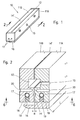
- Figure 1 shows a diagram of the device for dispensing or pouring polyurethane mixtures obtained by mixing, in a per se known manner, two or more chemically reactive liquid components, with possible additives and a foaming agent dissolved in solution, for example CO2 or another low-boiling foaming agent, in a mixing device not shown, immediately upstream the dispensing device.
- a foaming agent dissolved in solution for example CO2 or another low-boiling foaming agent
- the device shown comprises an elongated body 10, for example in the form of a bar which extends along a longitudinal axis, provided by two metal half-bars 11A and 11 B positioned alongside each other and disengageably fastened by bolts or by other connection means to maintaining them rigidly positioned and closed at the ends by plates 12.
- each half-bar 11A, 11 B is provided with a longitudinal slot which, in the assembled condition of figure 2 , contributes to perform a feeding path or conduit 13 for the distribution of a liquid polyurethane mixture along an exit slit 14 having a surface area which extends parallel and orthogonal to the conduit 13; alternatively, the conduit 13 could be performed in only one of the two half-bars 11A and 11 B.
- the conduit 13 is closed at both ends by plates 12 and communicates with a narrow exit slit 14 defining an exit meatus for the mixture which extends parallel to a side of the conduit 13 for a length L.
- Reference number 15 in figures 1 and 2 indicates a central inlet hole for feeding the polyurethane mixture to the distribution conduit 13, while reference number 14' indicates a metal sheet between the two half-bars 11A and 11 B, having a thickness corresponding to the height "H" of the meatus of exit slit 14, necessary for achieving a required hydraulic resistance or pressure drop, whereas reference number 16 indicates a flow deviator to attenuate the speed of the frothed foam outcoming the exit slit 14, to poure it in an homogeneous mode onto a substrate or into an open cavity of a mould.
- the exit slit 14 has substantially planar or facing side surface areas suitable to come into contact with the flowing polyurethane mixture, which extends parallel and orthogonally to the distribution conduit 13.
- meatus means a very restricted flow path, having an height M ranging from some tenths of millimetres to some millimetres, suitable to cause a gradual pressure drop and release of the foaming agent, while maintaining a laminar flow of the polyurethane mixture flowing along said path.
- the liquid polyurethane mixture has a high viscosity, equal to or higher than 100 cps, and a tendency to adhere to the contact surfaces of the exit slit 14, polymerizing and solidifying very rapidly. Therefore, over the time, on the contact surfaces of the dispensing device which are wet by the liquid polyurethane mixture, a layer of solidified mixture will build-up which tends to obstruct the conduit 13 and the exit slit 14; the increasing of the hardened layer over the time causes a progressive reduction of the pressure drop and a non homogeneous distribution of the frothed mixture.
- boundary layer of the polyurethane flowing mixture in conduit 13 and in the meatus of exit slit 14 refers to an ideal zone of the flow where the effects of viscosity and the laminar flow are more marked, i.e. in the close vicinity of the contact surfaces where the speed of the flow is very low.
- This phenomenon is fairly complex and depending from multiple factors which influence the thermal exchange between the cooling means of the dispensing device, and the boundary layer of liquid polyurethane mixture extending along the contact surfaces.
- the base reaction temperature T1 for conventional polyurethane formulations may be between 15° and 60°C, good results have been obtained by cooling the contact surfaces and consequently the boundary layer of liquid mixture, at a temperature from 3° to 70°C lower than T1, not excluding temperatures lower than 0°C, as a function of different process requirements, the formulation and reactivity of the polyurethane mixture, and the nature of the cooling fluid.
- Cooling of the mixture contact surfaces of the dispensing device may be performed by any suitable means, for example by a system of conduits for circulation of a cooling fluid, such as a mixture of water and glycol in appropriate percentages.
- a cooling fluid such as a mixture of water and glycol in appropriate percentages.
- each half-bar 11A and 11 B of the dispensing device may be shaped with at least one circulation conduit for the cooling fluid, which extends longitudinally for the entire length L of bar 10, including the end plates 12.
- each half-bar has a single longitudinal conduit consisting in a tubular pipe 17 fitted into a side open slot 18, subsequently closed by a layer of resin 19.
- the temperature of the contact surfaces of bar 10, and consequently the cooling temperature of the boundary layer of liquid polyurethane mixture may be appropriately controlled through one or more thermal probes threaded into holes 20 of each half-bar 11A, 11 B, on one or on both sides of the exit slit 14, for example between the distribution conduit 13 and the cooling fluid circulation pipe or pipes 17, in which the holes 20 for the insertion of the thermal probes extend up to slit 14.
- each half-bar 11A and 11 B has a single pipe 17 for circulation of the cooling fluid; a second solution is shown in figure 3 , where the same reference numbers have been used to indicate similar or equivalent parts to the example in figure 2 .
- each half-bar 11, for example half-bar 11A, partially shown, has two pipes 17' and 17" for circulation of a cooling fluid, which extend parallel to the slit 14.
- Pipes 17' and 17" may extend for the entire length of bar 10, as explained further on, or may be either independent or communicating with each other.
- Figure 3 also shows how each half-bar, in the specific case half-bar 11A, at its side surface defining the meatus of the slit 14, may be provided with means suitable for generating a turbulence in the flow of the mixture, since this facilitates the release of the foaming agent previously dissolved in the solution; consequently facilitates the formation of pre-expanded foam consisting of a dense cream or "froth".
- Cooling of the bar shaped dispensing device 10 and consequently of the contact surfaces with the polyurethane mixture may be performed constantly for the entire length of the bar as described in the example in figure 2 , or in a differentiated way along specific sections of the same bar, as shown in the examples of figures 4 and 5 , where the same reference numbers have been used as figure 3 to indicate similar or equivalent parts.
- a longitudinal section of half-bar 11A according to line 4-4 of figure 3 is shown; however, what will be said for the half-bar 11A may also be applied to half-bar 11B, for a dispensing device 10 according to the invention.
- the reference number 17' indicates a continuous cooling fluid circulation pipe or duct, now represented as a longitudinal hole which extends for the entire length of the bar, to allow circulation of a cooling fluid at an initial temperature T1.
- the reference number 17" indicates a second cooling fluid circulation pipe or duct, which partially extends on a side of the duct 17, starting from each end of the half-bar, in an intermediate position between internal duct 17' and the external edge of slit 14.
- ducts 17" extend symmetrically for approximately a third of the length of the slit 14, ending at a transversal hole 17"'; however, the length of the ducts 17" could also be different to what shown.
- the cooling fluid which circulates in the duct 17" could have the same temperature T1 of the fluid circulating in duct 17', or a temperature T2 higher or lower than T1. In this way, it is possible to achieve a differentiated cooling, greater at both ends of the bar compared with the central zone, where the phenomenon of polymerisation and premature hardening of the polyurethane mixture in the boundary layer is more critical.
- FIG 4 by reference number 17A has been indicated the possibility of a continuous duct, as for duct 17', as an alternative to two partial ducts 17".
- Figure 5 shows a further embodiment of the dispensing device 10 suitable to provide a differentiated cooling; once again in figure 5 , the same reference numbers have been used to indicate similar or equivalent parts.
- the example in figure 5 differs from the example in figure 4 in that now the first and the second ducts 17' and 17", starting from each end of bar 10, are connected to each other in an intermediate differentiated cooling zone.
- the cooling of the boundary layer should be performed to minimally influence the base temperature of the remaining mixture flowing into the meatus, due to the low thermal conductivity of the polyurethane mixture and the speed of the same mixture flowing along the distribution conduit 13 and the exit slit 14.
- Delaying a gas bubbles release in the boundary layer by cooling allows the mixture to be maintained in the liquid state along the contact surfaces; all this, besides delaying polymerisation of polyurethane mixture on the contact surface of the exit slit or tubular duct, allows also a continuous generation and a gradual expansion of gas bubbles of the low-boiling foaming agent in the boundary layer, along the entire length of the meatus, which cause a detachment of the same boundary layer in a still liquid state, from the contact surface, and the entrainment into the polyurethane mixture flowing along the exit slit, or tubular ducts. All this improves also the washing efficiency of the dispensing device by solvents, usually required after a short working time in a conventional device, the washing operation is facilitated since the solvent finds a boundary layer of unreacted mixture and in a liquid state.
- cooling is obtained by circulation of a chilling fluid; however, cooling may be performed in any other appropriate way, for example through expansion of a gas, or a low-boiling fluid for isenthalpic lamination, or by the use of half-conductor cells with Peltier effect, appropriately positioned in respective seatings.
- a meatus provided by parallel facing surfaces causes a linear pressure drop or pressure reduction along the lenght of the same meatus, corresponding to the dimension measured at a right-angle to the longitudinal extension of the exit slit 14, passing from the pressure existing in mixture within the distribution conduit 13 to ambient pressure.
- both problems may be solved by providing a higher specific flow rate QS of frothed polyurethane mixture at both ends of the bar shaped dispensing device 10, or in specific zones along lenght of the same device, in combination with cooling of the boundary layer of the mixture, as previously specified; figures 9 to 16 show some examples that will be described further on.
- Figure 6 once again shows a dispensing device 10 including two half-bars 11A and 11 B close together, as in figure 2 , defining a mixture distribution conduit 13, and a mixture exit slit 14, comprising a meatus having a constant height H for the entire length L of the slit, and a width B, as shown.
- Figure 8 shows a cross sectional view of the partially foamed polyurethane mixture, or "froth", poured onto a substrate 26 by a dispensing device 10 having the constant meatus of figure 6 ; it may be seen from figure 8 that the partially foamed mixture 25 has a highly tapered section on the sides, due to its expansion beyond the ends of the dispensing device.
- the tapering effect of the partially expanded polyurethane mixture 25 poured onto a substrate or into a mould by increasing the specific flow rate QS of the mixture at the two ends of the dispensing device 10, or by increasing the height H of the meatus of slit 14; this not only allows a distribution of the mixture 25 onto the substrate 26 with a higher cross section at the two ends to compensate the tendency to tapering, but the greater height H of the meatus at the two ends also shortens the time required for flowing the mixture towards the ends of the dispensing device, increasing the average speed and, in combination with the cooling of the boundary layer, decreases the stratification speed of the same boundary layer, and lastly improves the washing effectiveness with solvents of the unreacted polyurethane mixture.
- the two half-bars 11A and 11 B are shaped to define a slit 14 with a meatus of variable height H, including a central section 14A having a first height H1 which extends for a length L1, and a side section 14B at each end, with a second height H2 greater than the first one, which extends for length L2 less than L1.
- H2 may be 2% up to 220% higher than H1.
- L2 may vary between 3% up to 80% of L1.
- Figure 10 shows a graph of the specific flow rate for the dispensing device 10 of figure 9 , from which it may be seen that, at central meatus 14A, there is an initial specific flow rate of QS1, whereas, at the two end sections 14B of the meatus, there is a specific flow rate QS2 higher than the previous one.
- Figure 11 shows the cross sectional view of the frothed polyurethane mixture 25 upon release of the foaming agent, while it is poured onto a substrate 26, in which the foamed mixture has a greater cross section at the two ends 14B. Should the mixture be foamed between two half-moulds or two half-shells or shaped plates, this configuration allows distribution of a specific density which is much more uniform than in the case of fig. 8 .
- the meatus rather than in steps, could also change linearly from H1 to H2 along two end sections of slit 14; this is shown by way of example in figure 12 , where the same reference numbers as in the previous figures have been used once again, to indicate similar or equivalent parts.
- H1 once again indicate the height of the meatus along a central section 14A of the slit, which extends for a length L1
- 14B indicates a divergent meatus, with linear variability from H1 to H2 in the longitudinal direction, along each end section L2.
- Figure 13 shows the gradual variation of the specific flow rate from QS1 to QS2.
- Figures 14 and 15 show another solution in which the exit slit 14 has a meatus comprising several parts of constant height H, having an increasing value from the centre to the ends.
- the exit slit 14 has a meatus comprising several parts of constant height H, having an increasing value from the centre to the ends.
- the ratios between heights H and lengths L of the several portions of the meatus may be anyone, including different to the one shown in the diagram, as a function of specific requirements.
- the ratios between the different heights of the meatus of slit 14 may be any, in particular between 1,02 and 2,2; in figure 15 , a graph is shown of the three different specific flow rates QS1, QS2 and QS3, of increasing value from the centre towards the ends of the dispensing device 10.
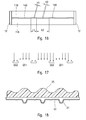
- Figures 16 to 18 show a further solution, in which the same reference numbers as the previous figures have been used to indicate similar or equivalent parts.
- the mixture exit slit in its longitudinal direction comprises several portions or zones 14A of length L1 with height H1 of the meatus, which alternate to portions 14B of length L2 with a meatus of height H2 greater than H1.
- the heights of meatus H1 and H2, like lengths L1 and L2, can be any; the solution in figure 16 is particularly advantageous for obtaining a different distribution of specific flow rates QS1 and QS2, as shown in figure 17 , and consequently increasing or reducing the pouring of the polyurethane mixture into a cavity, for example at ribbing 21 of a shaped metal sheet 22 for foaming panels, figure 18 , or for similar applications.
- FIGS 19 and 20 show another solution in which the same reference numbers as the previous figures have once again been used to indicate similar or equivalent parts.
- figure 19 shows a top view of a half-bar 14A
- figure 20 shows the specific flow rate QS.
- the solution in figure 19 differs from the previous ones, in relation to the different outline and variable width B of the lateral surfaces which define the mixture outlet meatus.
- the meatus had constant width B
- the meatus has a width gradually decreasing from a value B1, at the centre, to a value B2, lower than the previous one at each end. Since, according to the previous formula "1", the specific flow rate QS also depends on width B of the meatus, it follows that the specific flow rate QS will gradually vary from a minimum value QS1 at the centre of the slit, to a maximum value QS2 at the ends of the slit, as shown in figure 20 .
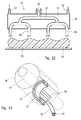
- Figure 21 shows a view similar to figure 6 , in which, as an alternative to slit 14 of device 10, the bar-shaped dispensing device is conformed with a number of small tubular ducts 14D side by side arranged in the longitudinal direction of the device 10, consisting of dispensing ducts of any shape, for example with a circular or half-circular section as shown, triangular, or other one on a half-bar 11A, or on both half-bars of the dispensing device 10.
- Figure 22 shows another embodiment of the dispensing device 10; the solution in figure 22 differs from the previous one, both in the polyurethane mixture dispensing and cooling system.
- the device in figure 22 once again includes a mixture distribution conduit 27 which extends longitudinally to the body of a bar-shaped dispensing device having a central inlet 28 for the polyurethane mixture.
- the distribution conduit 27, from the opposite side to the inlet 28, at each end communicates with two or more tubular ducts 29 for pouring and dispensing the mixture 25 onto a substrate 26.
- the meatus of the tubular ducts 29, like the meatus of slit 14, perform the task of distributing the mixture and controlling the pressure drop ⁇ P and the release of the foaming agent between, in a range between 0.2 and 6 MPa.
- cooling of conduit 27 and ducts 29, and consequently the cooling of the boundary layer of the mixture in the conduit 27 and in each duct 29, is obtained by enclosing said conduit and ducts in a cooling chamber 31 of a box-shaped body 30, in which a cooling fluid is made to circulate between inlet 32 and outlet 33.
- tubular ducts 29 protrude partially from a bottom wall of the box-shaped body 30, as shown.
- Figure 22 shows also the cross section of the partially foamed mixture 25, poured onto the substrate 26.
- the mixture dispensing device 10 is in the form of a straight bar body which extends along a longitudinal axis parallel to a planar substrate, or to metal sheets on which the polyurethane foam is dispensed, in the production of panels, or for similar applications.
- the dispensing device according to the invention could have any other shape or conformation, on the basis of specific requirements in use.
- FIG. 23 An example is shown in figure 23 , in which the dispensing device 10 is in the form of an arc shaped body, in which the exit slit 14 is positioned on a side of device 10.
- This device may be used to supply a pre-foamed foam in a frothed condition by a low-boiling foaming agent, for manufacturing insulated pipes used, for example, for distribution of heating or refrigerating fluids, such as steam water.
- an isolated pipe usually comprises an internal steel pipe 37 and an external sheath 38 of greater diameter, between which a layer of insulating polyurethane material not shown, is injected by an arc shaped dispensing device 10, which is moved inside the annular hollow space between the internal pipe 37 and the external sheath 38.
- the external sheath may be a high-density plastic tube or sheets of polyethylene material or another suitable material, longitudinally wrapped around the internal pipe and the polyurethane foam.
- dispensing device 10 in figure 23 is entirely similar and is cooled in a similar way to device 10 in the previous figures, with the sole difference that the dispensing device now in the form of an arc shaped body with internal and external bending radii corresponding to those of tube 37 and sheath 38.
- reference number 34 indicates also a polyurethane mixture feeding pipe
- reference numbers 35 and 36 indicate the feeding and return pipes for the cooling fluid.
- a bar-shaped dispensing device 10 similar to the one in figure 1 and 2 was used, with a meatus of constant height, obtaining good and unexpected results.
- the base reaction temperature T1 of the polyurethane mixture fed to the dispensing device 10, during the various tests ranged between approximately 18° and 30°C. Consequently, a cooling fluid was circulated at a temperature T0 lower than the basic reaction temperature T1 of the polyurethane mixture, for example between 0°C and a temperature a few degrees lower than the basic reaction temperature T1, for example 5°C.
- the temperature of the contact surfaces of the dispensing device 10, near the boundary layer, was controlled by a temperature detecting system comprising thermal probes and by a closed loop regulation system to change the temperature of the cooling fluid between the values indicated above, to maintain a constant cooling temperature of the dispensing device which is influenced by change in the amount of heat, depending on corresponding changes in the flow rate of the polyurethane mixture.
- the polyurethane mixture partially foamed with CO2 consisted of homogenous cells of good dimensions, less than 0.3 mm, and with homogenous density between 21 and 60 Kg/m 3 .
- the device 10 was opened by separating the two half-bars 11A and 11B; it was discovered that even after a continued use, there was no formation of solidified mixture, but only a viscous patina of unreacted mixture, since the chemical reaction between the polyurethane components in the boundary layer and the generation of gas bubbles of the low-boiling agent has been delayed by cooling continuously removing the unreacted boundary layer along the entire length of the slit.
- the dispensing device 10 could be cleaned completely by washing with solvent, keeping the distribution conduit and the dispensing meatus free from any built-up and blockage.
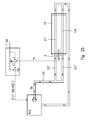
- FIGS 24 and 25 show two possible embodiments of cooling fluid control and circulation systems, although other solutions are possible on the basis of specific requirements and the particular shape of the device for dispensing the polyurethane mixture.
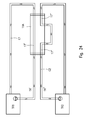
- Figure 24 shows the example of a first cooling system comprising two independent circuits for the cooling media, of the open loop type, in a mixture dispensing device 10 of the type shown in figure 4 .
- the cooling system in figure 24 includes a first circuit C1 for feeding the cooling fluid to conduits 17' of both half-bars, one only shown, connected to a device TR1 for generation and circulation of a fluid cooled to a thermoregulated temperature TR', capable of generating a flow of a cooling fluid, for example a mixture of water and glycol, of the type commonly known as a thermoregulating chillier, for example of type RACA 40 produced by Frigo-system.
- a thermoregulating chillier for example of type RACA 40 produced by Frigo-system.
- the system in figure 24 includes a second circuit C2 for the conduit 17" in each half-bar 11A and 11 B, connected to a second thermoregulated cooling device TR2, similar to the previous one, for circulation of a cooling fluid at a thermoregulated temperature TR" different from TR'.
- the first thermoregulating device TR1 may be set to circulate a cooling fluid at a temperature T1
- the second thermoregulating device TR2 may be set to circulate a cooling fluid at a temperature T2 which may be equal to or different from temperature T1
- both thermoregulating devices TR1 and TR2 may be operated to circulate the cooling fluid in the dispensing device 10 at a temperature of a basically constant value, which may be chosen each time on the basis of the formulation of the polyurethane mixture.
- the control of the temperature of the mixture contact surface of the dispensing device 10 is, through control of the temperature of the fluid by the thermoregulated cooling device TR1 and TR2.
- Figure 25 shows, by way of example, a second temperature control system, of a closed loop type, for a dispensing device 10 in which the conduits 17' and 17A for circulation of the cooling fluid conform to the solution in figure 4 .
- the cooling system includes a cooling and thermoregulating device TR3, connected to a single circuit C3 having two branches C3' and C3" for feeding the cooling fluid to the two conduits 17' and 17A of the dispensing device 10.
- the temperature of the cooling system is regulated by a closed loop control system, which may use two signals:
- the closed loop system also includes one or more probes S for detecting the temperature of device 10, the outlet signal of which is sent to a comparison node N1 of the thermoregulating control device TR3.
- the invention relates to a method and a device suitable for dispensing a frothed polyurethane mixture which has been pre-expanded by means of a low-boiling foaming agent dissolved in solution, in which the polyurethane mixture is fed, under pressure, to a dispensing device comprising a distribution conduit for the polyurethane mixture in fluid communication with the meatus of an elongated dispensing slit provided with spaced apart facing surfaces which extend longitudinally and orthogonally to the distribution conduit, or in fluid communication with the meatus of tubular ducts for dispensing the pre-expanded or frothed mixture.
- the meatus is dimensioned to cause a gradual pressure reduction and a gradual releasing of the low-boiling foaming agent, in a gas form, into the liquid polyurethane mixture of the boundary layer to dispense or pouring a polyurethane froth into a mould or onto a substrate; the elongated slit or the tubular ducts are provided with a contact surface for a boundary layer of liquid polyurethane mixture flowing along the pressure reduction and low-boiling agent releasing meatus, at a base reaction temperature for the chemical components.
- the innovative feature resides in cooling the boundary layer of the polyurethane mixture along the meatus by maintaining the contact surface of the slit or tubular ducts, to a selected cooling temperature lower than the base reaction temperature and consequently to release in a gaseous form, and cause a progressive expansion of bubbles of low-boiling foaming agent into the boundary layer of the polyurethane mixture, for the entire length of the meatus of the elongated slit, or tubular ducts.
- the chemical layer and its adhesion to the contact surface of the slit or tubular duct is therefore drastically reduced and removed for a long time, by the expanding gas-bubbles of the low-boiling agent released along the meatus of the slit, or tubular ducts.
- the meatus of the elongated slit 14 of a bar-shaped dispensing device 10 provide a hydraulic resistance to maintain a high and constant pressure drop, usually in the range of 0,4 to 4 MPa, between the distribution conduit 13 and outside the meatus of the exit slit 14; this pressure drop is suitable to cause over the time an homogeneous distribution and a constant flux of a liquid polyurethane mixture, because makes unaffected any pressure difference along the distribution conduit 13 depending on the drainage of the mixture along the longitudinal extension of the same slit.
- cooling in combination with the pressure drop is suitable to control the releasing and expansion of bubbles of gas B of the low-boiling foaming agent, or emulsified air, from the distribution conduit 13, which develops in the boundary layer BL along the meatus from the distribution conduit 13.
- the cooling has been forseen of the boundary layer of the polyurethane mixture, at a temperature Ts suitable to allow a delayed generation of gas bubbles, substantially for the entire length L of the meatus.
- ⁇ T that is a cooling temperature for the boundary layer, such as the time required for generation of gas bubbles, sufficient to generate at least the 63% of the gas bubbles, in respect to the entire member calculate on the basis of formula "2"
- ⁇ T should be selected between 1,2 and 12 times the average time for the polyurethane mixture to flow along the meatus, in which said average time is provided by ratio L/Vaverage, between the width L of the meatus and the average velocity of the laminar flux, calculated in a conventional mode, in a cross direction of the meatus.
Landscapes
- Engineering & Computer Science (AREA)
- Mechanical Engineering (AREA)
- Manufacture Of Porous Articles, And Recovery And Treatment Of Waste Products (AREA)
- Casting Or Compression Moulding Of Plastics Or The Like (AREA)
- Polyurethanes Or Polyureas (AREA)
Applications Claiming Priority (1)
| Application Number | Priority Date | Filing Date | Title |
|---|---|---|---|
| IT000028A ITMI20090028A1 (it) | 2009-01-14 | 2009-01-14 | Procedimento e dispositivo raffreddato per l'erogazione di miscele poliuretaniche. |
Publications (1)
| Publication Number | Publication Date |
|---|---|
| EP2208599A1 true EP2208599A1 (de) | 2010-07-21 |
Family
ID=41349349
Family Applications (1)
| Application Number | Title | Priority Date | Filing Date |
|---|---|---|---|
| EP10150737A Withdrawn EP2208599A1 (de) | 2009-01-14 | 2010-01-14 | Verfahren und gekühlte Vorrichtung zur Abgabe von Polyurethangemischen |
Country Status (2)
| Country | Link |
|---|---|
| EP (1) | EP2208599A1 (de) |
| IT (1) | ITMI20090028A1 (de) |
Cited By (4)
| Publication number | Priority date | Publication date | Assignee | Title |
|---|---|---|---|---|
| WO2016037842A1 (en) * | 2014-09-11 | 2016-03-17 | Huntsman International Llc | Method of designing and manufacturing a distributor bar for applying a viscous foamable liquid mixture onto a laminator |
| WO2017021463A1 (de) * | 2015-08-04 | 2017-02-09 | Covestro Deutschland Ag | Giessvorrichtung zum auftragen eines aufschäumenden reaktionsgemisches |
| EP3354671A1 (de) | 2017-01-31 | 2018-08-01 | Covestro Deutschland AG | Verfahren zur herstellung von polyurethan (pur) und polyurethan/polyisocyanurat (pur/pir)- hartschaumstoffen |
| WO2024254366A1 (en) * | 2023-06-09 | 2024-12-12 | Dow Global Technologies Llc | Method for producing corrugated laminated panels |
Citations (10)
| Publication number | Priority date | Publication date | Assignee | Title |
|---|---|---|---|---|
| FR1449836A (fr) * | 1965-07-06 | 1966-05-06 | Chausson Usines Sa | Dispositif répartiteur pour produits visqueux, installation le comportant et application de ce dispositif à la répartition de résines synthétiques |
| US4298557A (en) * | 1979-12-12 | 1981-11-03 | The Dow Chemical Company | Method and apparatus for the preparation of foamed structures |
| US4900593A (en) * | 1987-09-02 | 1990-02-13 | Bayer Aktiengesellschaft | Process and device for applying a free-flowing reaction mixture |
| EP0645226A2 (de) | 1993-07-14 | 1995-03-29 | Foaming Technologies Cardio B.V. | Schlagverfahren und System zur kontinuierlichen Herstellung von Polyurethanschaumstoffblocken |
| EP0683027A2 (de) * | 1994-05-17 | 1995-11-22 | Nordson Corporation | Vorrichtung und Verfahren zum Giessen von Schaummaterial |
| US5512222A (en) | 1995-03-15 | 1996-04-30 | Foamex L.P. | Method of using a chilled trough for producing slabs of polyurethane foam |
| EP0767728A1 (de) | 1994-06-28 | 1997-04-16 | Bayer Ag | Verfahren und vorrichtung zur schaumherstellung mittels unter druck gelöstem kohlendioxid |
| EP0800905A2 (de) * | 1996-04-12 | 1997-10-15 | EXTRUSION DIES, Inc. | Extrusionsschlitzdüse für Hartschaumplatten |
| US6147133A (en) * | 1996-05-24 | 2000-11-14 | Hennecke Gmbh | Process and device for producing foam using carbon dioxide dissolved under pressure |
| WO2001010623A1 (en) | 1999-08-09 | 2001-02-15 | Worldwide Polyurethanes B.V. | Process and device for dispensing polyurethane foaming material |
-
2009
- 2009-01-14 IT IT000028A patent/ITMI20090028A1/it unknown
-
2010
- 2010-01-14 EP EP10150737A patent/EP2208599A1/de not_active Withdrawn
Patent Citations (10)
| Publication number | Priority date | Publication date | Assignee | Title |
|---|---|---|---|---|
| FR1449836A (fr) * | 1965-07-06 | 1966-05-06 | Chausson Usines Sa | Dispositif répartiteur pour produits visqueux, installation le comportant et application de ce dispositif à la répartition de résines synthétiques |
| US4298557A (en) * | 1979-12-12 | 1981-11-03 | The Dow Chemical Company | Method and apparatus for the preparation of foamed structures |
| US4900593A (en) * | 1987-09-02 | 1990-02-13 | Bayer Aktiengesellschaft | Process and device for applying a free-flowing reaction mixture |
| EP0645226A2 (de) | 1993-07-14 | 1995-03-29 | Foaming Technologies Cardio B.V. | Schlagverfahren und System zur kontinuierlichen Herstellung von Polyurethanschaumstoffblocken |
| EP0683027A2 (de) * | 1994-05-17 | 1995-11-22 | Nordson Corporation | Vorrichtung und Verfahren zum Giessen von Schaummaterial |
| EP0767728A1 (de) | 1994-06-28 | 1997-04-16 | Bayer Ag | Verfahren und vorrichtung zur schaumherstellung mittels unter druck gelöstem kohlendioxid |
| US5512222A (en) | 1995-03-15 | 1996-04-30 | Foamex L.P. | Method of using a chilled trough for producing slabs of polyurethane foam |
| EP0800905A2 (de) * | 1996-04-12 | 1997-10-15 | EXTRUSION DIES, Inc. | Extrusionsschlitzdüse für Hartschaumplatten |
| US6147133A (en) * | 1996-05-24 | 2000-11-14 | Hennecke Gmbh | Process and device for producing foam using carbon dioxide dissolved under pressure |
| WO2001010623A1 (en) | 1999-08-09 | 2001-02-15 | Worldwide Polyurethanes B.V. | Process and device for dispensing polyurethane foaming material |
Cited By (7)
| Publication number | Priority date | Publication date | Assignee | Title |
|---|---|---|---|---|
| WO2016037842A1 (en) * | 2014-09-11 | 2016-03-17 | Huntsman International Llc | Method of designing and manufacturing a distributor bar for applying a viscous foamable liquid mixture onto a laminator |
| US10328450B2 (en) | 2014-09-11 | 2019-06-25 | Huntsman International Llc | Method of designing and manufacturing a distributor bar for applying a viscous foamable liquid mixture onto a laminator |
| WO2017021463A1 (de) * | 2015-08-04 | 2017-02-09 | Covestro Deutschland Ag | Giessvorrichtung zum auftragen eines aufschäumenden reaktionsgemisches |
| EP3354671A1 (de) | 2017-01-31 | 2018-08-01 | Covestro Deutschland AG | Verfahren zur herstellung von polyurethan (pur) und polyurethan/polyisocyanurat (pur/pir)- hartschaumstoffen |
| WO2018141721A1 (de) | 2017-01-31 | 2018-08-09 | Covestro Deutschland Ag | Verfahren zur herstellung von polyurethan (pur) und polyurethan/polyisocyanurat (pur/pir) – hartschaumstoffen |
| CN110248980A (zh) * | 2017-01-31 | 2019-09-17 | 科思创德国股份有限公司 | 制备聚氨酯(pur)和聚氨酯/聚异氰脲酸酯(pur/pir)硬质泡沫材料的方法 |
| WO2024254366A1 (en) * | 2023-06-09 | 2024-12-12 | Dow Global Technologies Llc | Method for producing corrugated laminated panels |
Also Published As
| Publication number | Publication date |
|---|---|
| ITMI20090028A1 (it) | 2010-07-15 |
Similar Documents
| Publication | Publication Date | Title |
|---|---|---|
| EP2208599A1 (de) | Verfahren und gekühlte Vorrichtung zur Abgabe von Polyurethangemischen | |
| US8709313B2 (en) | Method and apparatus for feeding a polyurethane mixture into hollow bodies | |
| Amon et al. | A study of the dynamics of foam growth: simplified analysis and experimental results for bulk density in structural foam molding | |
| Abate et al. | One-step formation of multiple emulsions in microfluidics | |
| CN103861490B (zh) | 静态混合器 | |
| JP3515762B2 (ja) | 連続鋳造用浸漬ノズル並びに連続鋳造方法 | |
| Bellantone et al. | Evaluation of mold roughness influence on injected thin micro-cavities | |
| JP3156922B2 (ja) | 半固体金属射出成型の方法及び装置 | |
| WO2008054061A1 (en) | Method for preparation of microcellular foam with uniform foaming ratio and extruding and foaming system for the same | |
| JP2008272752A (ja) | 幅広の基体に発泡体を吐出する装置並びに方法 | |
| EP3838567B1 (de) | Verfahren und vorrichtung zum giessen einer spritzerfreien polymermischung | |
| Throne | Structural foam molding parameters | |
| EP0573749B1 (de) | Intermittierende Heizvorrichtung für plastifizierte Fluide in Spritzgiessen oder dergleichen | |
| EP3972802B1 (de) | Verfahren und vorrichtung zur echtzeitsteuerung der injektion von strukturschaumstoffen, farbstoffen und anderen additiven | |
| CN103189174B (zh) | 制备发泡模塑物的方法 | |
| JP2008018677A (ja) | 発泡樹脂成形品の成形方法及び成形装置 | |
| US7575046B2 (en) | Methods for stabilizing flow in channels and systems thereof | |
| EP1216131B1 (de) | Vorrichtung und verfahren zur ausgabe von polyurethanschaummaterial | |
| JP2010162823A (ja) | 発泡樹脂成形品の成形方法及び成形装置 | |
| CA2705297C (en) | Casting system with a device for applying a casting strip | |
| JP2002292722A (ja) | 押出発泡複合体の製造方法及び装置 | |
| JP2009078516A (ja) | 発泡シート製造用tダイ、発泡シート製造装置、発泡シート及び発泡シートの製造方法 | |
| Choudhary et al. | Modeling of three‐dimensional flow and heat transfer in polystyrene foam extrusion dies | |
| CN114248388A (zh) | 成型方法 | |
| Lee et al. | Extrusion of high-density and low-density micro-cellular plastics |
Legal Events
| Date | Code | Title | Description |
|---|---|---|---|
| PUAI | Public reference made under article 153(3) epc to a published international application that has entered the european phase |
Free format text: ORIGINAL CODE: 0009012 |
|
| AK | Designated contracting states |
Kind code of ref document: A1 Designated state(s): AT BE BG CH CY CZ DE DK EE ES FI FR GB GR HR HU IE IS IT LI LT LU LV MC MK MT NL NO PL PT RO SE SI SK SM TR |
|
| STAA | Information on the status of an ep patent application or granted ep patent |
Free format text: STATUS: THE APPLICATION IS DEEMED TO BE WITHDRAWN |
|
| 18D | Application deemed to be withdrawn |
Effective date: 20101123 |