EP2208865A2 - Verfahren zur Reparatur von verformten Bauteilen in einem Gasturbinentriebwerk - Google Patents
Verfahren zur Reparatur von verformten Bauteilen in einem Gasturbinentriebwerk Download PDFInfo
- Publication number
- EP2208865A2 EP2208865A2 EP09250930A EP09250930A EP2208865A2 EP 2208865 A2 EP2208865 A2 EP 2208865A2 EP 09250930 A EP09250930 A EP 09250930A EP 09250930 A EP09250930 A EP 09250930A EP 2208865 A2 EP2208865 A2 EP 2208865A2
- Authority
- EP
- European Patent Office
- Prior art keywords
- component
- identifying
- heat
- behaves
- stiffener
- Prior art date
- Legal status (The legal status is an assumption and is not a legal conclusion. Google has not performed a legal analysis and makes no representation as to the accuracy of the status listed.)
- Granted
Links
Images

Classifications
-
- F—MECHANICAL ENGINEERING; LIGHTING; HEATING; WEAPONS; BLASTING
- F01—MACHINES OR ENGINES IN GENERAL; ENGINE PLANTS IN GENERAL; STEAM ENGINES
- F01D—NON-POSITIVE DISPLACEMENT MACHINES OR ENGINES, e.g. STEAM TURBINES
- F01D25/00—Component parts, details, or accessories, not provided for in, or of interest apart from, other groups
- F01D25/24—Casings; Casing parts, e.g. diaphragms, casing fastenings
-
- B—PERFORMING OPERATIONS; TRANSPORTING
- B23—MACHINE TOOLS; METAL-WORKING NOT OTHERWISE PROVIDED FOR
- B23P—METAL-WORKING NOT OTHERWISE PROVIDED FOR; COMBINED OPERATIONS; UNIVERSAL MACHINE TOOLS
- B23P6/00—Restoring or reconditioning objects
- B23P6/002—Repairing turbine components, e.g. moving or stationary blades, rotors
-
- B—PERFORMING OPERATIONS; TRANSPORTING
- B23—MACHINE TOOLS; METAL-WORKING NOT OTHERWISE PROVIDED FOR
- B23P—METAL-WORKING NOT OTHERWISE PROVIDED FOR; COMBINED OPERATIONS; UNIVERSAL MACHINE TOOLS
- B23P9/00—Treating or finishing surfaces mechanically, with or without calibrating, primarily to resist wear or impact, e.g. smoothing or roughening turbine blades or bearings; Features of such surfaces not otherwise provided for, their treatment being unspecified
-
- F—MECHANICAL ENGINEERING; LIGHTING; HEATING; WEAPONS; BLASTING
- F05—INDEXING SCHEMES RELATING TO ENGINES OR PUMPS IN VARIOUS SUBCLASSES OF CLASSES F01-F04
- F05D—INDEXING SCHEME FOR ASPECTS RELATING TO NON-POSITIVE-DISPLACEMENT MACHINES OR ENGINES, GAS-TURBINES OR JET-PROPULSION PLANTS
- F05D2230/00—Manufacture
- F05D2230/10—Manufacture by removing material
-
- F—MECHANICAL ENGINEERING; LIGHTING; HEATING; WEAPONS; BLASTING
- F05—INDEXING SCHEMES RELATING TO ENGINES OR PUMPS IN VARIOUS SUBCLASSES OF CLASSES F01-F04
- F05D—INDEXING SCHEME FOR ASPECTS RELATING TO NON-POSITIVE-DISPLACEMENT MACHINES OR ENGINES, GAS-TURBINES OR JET-PROPULSION PLANTS
- F05D2230/00—Manufacture
- F05D2230/40—Heat treatment
-
- F—MECHANICAL ENGINEERING; LIGHTING; HEATING; WEAPONS; BLASTING
- F05—INDEXING SCHEMES RELATING TO ENGINES OR PUMPS IN VARIOUS SUBCLASSES OF CLASSES F01-F04
- F05D—INDEXING SCHEME FOR ASPECTS RELATING TO NON-POSITIVE-DISPLACEMENT MACHINES OR ENGINES, GAS-TURBINES OR JET-PROPULSION PLANTS
- F05D2230/00—Manufacture
- F05D2230/80—Repairing, retrofitting or upgrading methods
-
- F—MECHANICAL ENGINEERING; LIGHTING; HEATING; WEAPONS; BLASTING
- F05—INDEXING SCHEMES RELATING TO ENGINES OR PUMPS IN VARIOUS SUBCLASSES OF CLASSES F01-F04
- F05D—INDEXING SCHEME FOR ASPECTS RELATING TO NON-POSITIVE-DISPLACEMENT MACHINES OR ENGINES, GAS-TURBINES OR JET-PROPULSION PLANTS
- F05D2260/00—Function
- F05D2260/94—Functionality given by mechanical stress related aspects such as low cycle fatigue [LCF] of high cycle fatigue [HCF]
-
- F—MECHANICAL ENGINEERING; LIGHTING; HEATING; WEAPONS; BLASTING
- F05—INDEXING SCHEMES RELATING TO ENGINES OR PUMPS IN VARIOUS SUBCLASSES OF CLASSES F01-F04
- F05D—INDEXING SCHEME FOR ASPECTS RELATING TO NON-POSITIVE-DISPLACEMENT MACHINES OR ENGINES, GAS-TURBINES OR JET-PROPULSION PLANTS
- F05D2260/00—Function
- F05D2260/94—Functionality given by mechanical stress related aspects such as low cycle fatigue [LCF] of high cycle fatigue [HCF]
- F05D2260/941—Functionality given by mechanical stress related aspects such as low cycle fatigue [LCF] of high cycle fatigue [HCF] particularly aimed at mechanical or thermal stress reduction
-
- Y—GENERAL TAGGING OF NEW TECHNOLOGICAL DEVELOPMENTS; GENERAL TAGGING OF CROSS-SECTIONAL TECHNOLOGIES SPANNING OVER SEVERAL SECTIONS OF THE IPC; TECHNICAL SUBJECTS COVERED BY FORMER USPC CROSS-REFERENCE ART COLLECTIONS [XRACs] AND DIGESTS
- Y10—TECHNICAL SUBJECTS COVERED BY FORMER USPC
- Y10T—TECHNICAL SUBJECTS COVERED BY FORMER US CLASSIFICATION
- Y10T29/00—Metal working
- Y10T29/49—Method of mechanical manufacture
- Y10T29/49316—Impeller making
- Y10T29/49318—Repairing or disassembling
-
- Y—GENERAL TAGGING OF NEW TECHNOLOGICAL DEVELOPMENTS; GENERAL TAGGING OF CROSS-SECTIONAL TECHNOLOGIES SPANNING OVER SEVERAL SECTIONS OF THE IPC; TECHNICAL SUBJECTS COVERED BY FORMER USPC CROSS-REFERENCE ART COLLECTIONS [XRACs] AND DIGESTS
- Y10—TECHNICAL SUBJECTS COVERED BY FORMER USPC
- Y10T—TECHNICAL SUBJECTS COVERED BY FORMER US CLASSIFICATION
- Y10T29/00—Metal working
- Y10T29/49—Method of mechanical manufacture
- Y10T29/49718—Repairing
- Y10T29/49748—Repairing by shaping, e.g., bending, extruding, turning, etc.
Definitions
- This disclosure relates to engine component repairs involving heat treatment.
- Engine components such as case structures for gas turbine engines, can become worn or damaged during use.
- distorted features like bulges, can develop in case walls and necessitate gas turbine engine case replacement or repair.
- replacement of worn and damaged parts can be expensive, while repairs to existing parts can be more cost-effective.
- known methods for repairing distorted features in annular cases involve heat treatment, which tends to induce new distortions in the part leading to a need for substantial rework. This has made case repairs impractical or uneconomical. It is desired to provide a cost effective and efficient repair method to enable repairs to engine cases with distorted features.
- a method for repairing a gas turbine engine component includes identifying a distorted feature located in a first portion of the component, identifying a second portion of the component that behaves as at least one of a heat sink or a stiffener, removing the second portion of the component from the first portion, cold working the first portion of the component to repair the distorted feature, heat treating the first portion of the component, and metallurgically joining the first portion of the component to the second portion of the component.
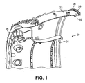
- FIG. 1 is a cross-sectional perspective view of a diffuser case for a gas turbine engine.
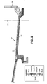
- FIG. 2 is cross-sectional view of an outer diameter wall portion of the diffuser case, shaded to show temperature gradients.
- FIG. 3 is a perspective view of an outer case segment for a gas turbine engine.
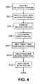
- FIG. 4 is a flow chart of a repair method.
- FIG. 1 is a cross-sectional perspective view of a diffuser case 20 for a gas turbine engine.
- the diffuser case 20 is typically located aft of a compressor section of the engine and has a cross-sectional flow area in the direction that increases in a downstream direction in order to decrease velocity and increase static pressure of fluid passing therethrough, which helps prepare the fluid for mixing with fuel for combustion.
- the general configuration and operation of gas turbine engines is well known in the art, and therefore is not discussed in detail here.
- the diffuser case 20 includes an outer wall 22, an inner wall 24, a plurality of vanes 26 located at a forward end of the case 20, and an aft flange 28 extending from the outer wall 22.
- a plurality of circumferentially spaced bolt holes 30 are formed in the aft flange 28, which enable the diffuser case 20 to be mechanically connected to other components of an engine.
- Undesirable distorted features, such as a bulge 32 can develop in the outer wall 22 (or other locations) during use and necessitate replacement or repair of the diffuser case 20.
- FIG. 2 is cross-sectional view of a portion of the outer wall 22 of the diffuser case 20.
- the portion of the diffuser case 20 shown in FIG. 2 is shaded to show temperature gradients in red, orange, yellow, green, cyan, and blue, where red represents the highest temperature, blue represents the lower temperature and the remaining colors designate intermediate temperatures (with magnitudes that vary between those of red and blue in the order listed).
- the shaded temperature gradients represent heat affected zones in the diffuser case 20 in response to applied heat, such as heat produced during a heat treatment process. Red areas tend to experience greater thermal expansion (or growth), while blue areas tend to experience lesser or the least thermal expansion. Portions of the diffuser case 20 that experience the least thermal expansion in response to applied heat tend to act like heat sinks.
- Heat sinks tend to deflect less than other portions of the diffuser case 20 when heat is applied, which can induce distortion in the diffuser case 20 during a repair heat treatment. Structures that are configured as relatively large concentrations of materials or configured with certain geometric properties, can also behave as stiffeners, which may restrict growth and movement of other heat affected zones during heat treatment. In the illustrated embodiment, the aft flange 28 tends to act as both a heat sink and a stiffener in the diffuser case 20.
- a cut plane 34 can be determined at a relatively low-stress location, and the aft flange 28 can be removed from the rest of the diffuser case 20 at the cut plane 34.
- Known machining processes can be used to remove the aft flange 28.
- the salvaged flange 28 or a new replacement detail configured like the flange 28 can be reattached to the diffuser case 20 with a suitable welding process (e.g., electron beam welding).
- a suitable welding process e.g., electron beam welding
- the replacement material can be the same or different from the parent material of the diffuser case 20.
- Use of a replacement detail of different material is disclosed in our European patent application claiming priority of US 12/356321 . Limited heat treatment, with suitable fixturing, can be performed on the weld joint after the flange 28 (or new replacement detail) is reattached.
- FIG. 3 is a perspective view of an outer case segment 120 for case assembly of a gas turbine engine.
- the case segment 120 is configured to be connected to a plurality of additional case segments in order to form an annular case assembly, in a manner well known in the art.
- the case segment 120 includes an outer case wall 122, and forward, middle and aft flanges 128A, 128B and 128C, respectively.
- Bolt holes 130 are formed in both the forward and aft flanges 128A and 128C.
- the forward, middle and aft flanges 128A, 128B and 128C which each act as both stiffeners and heat sinks, can all be removed from the outer case wall 122 prior to performing cold work and heat treatment on the case segment 120.
- the salvaged flanges 128A-128C or one or more new replacement details configured like the flanges 128A-128C can be reattached to the case segment 120 with a suitable welding process.
- Limited heat treatment, with suitable fixturing can be performed on the weld joint after the flanges 128-128C (or new replacement details) are reattached.
- FIG. 4 is a flow chart of one embodiment of a repair method.
- a first step is to identify a distorted feature or other aspect in need of repair (step 200).
- the distorted feature or other aspect in need of repair can be located in a first portion of the component.
- at least one heat sink and/or stiffener is identified (step 202). Identification of the heat sink and/or stiffener can be performed by visual inspection to locate area of concentration of material. Alternatively, other methods can be used, such as the use of thermal sensing equipment to identify thermal gradients produced as a function of applied heat.
- the heat sink and/or stiffener includes a flange.
- a second portion of the component that includes the heat sink and/or stiffener is removed from the first portion (step 204). Removal can be accomplished using known machining techniques.
- cold work is performed on the first portion of the component to repair the distorted feature or other aspect in need of repair (step 206). Cold work can include any known cold working techniques, which are generally selected to correspond to the particular distorted feature or other aspect in need of repair that is present on a given component, as will be understood by those of ordinary skill in the art.
- the first portion of the component, with the second portion removed can then be placed in a furnace to provide heat treatment (step 208).
- the first portion is metallurgically joined to the second portion (which can be the salvaged material previously removed or a new replacement detail of substantially the same shape as the removed material) (step 210). Electron beam or other welding techniques can be used to weld the first and second portions at this step. Lastly, focused or limited heat treatment can be performed on a region of the weld between the first and second portions, with suitable fixturing to reduce a risk of distortion to the component (step 212). The repaired part can then be reinstalled in the engine and returned to service.
- component walls can grow and otherwise behave differently than they otherwise would during heat treatment. This can help reduce the creation of distortions in the component during heat treatment, thereby reducing the need for rework in conjunction with a repair. Overall this can help reduce repair turnaround time (TAT) and costs, and provide a relatively efficient and effective repair for returning worn or damaged engine components to service.
- TAT repair turnaround time
- repair method can be applied to engine components have different configurations than the exemplary embodiments disclosed herein, and can be performed in conjunction with other repair processes not specifically mentioned.
Landscapes
- Engineering & Computer Science (AREA)
- Mechanical Engineering (AREA)
- General Engineering & Computer Science (AREA)
- Butt Welding And Welding Of Specific Article (AREA)
- Turbine Rotor Nozzle Sealing (AREA)
- Laser Beam Processing (AREA)
Applications Claiming Priority (1)
| Application Number | Priority Date | Filing Date | Title |
|---|---|---|---|
| US12/356,341 US8281487B2 (en) | 2009-01-20 | 2009-01-20 | Control of case wall growth during repair and method |
Publications (3)
| Publication Number | Publication Date |
|---|---|
| EP2208865A2 true EP2208865A2 (de) | 2010-07-21 |
| EP2208865A3 EP2208865A3 (de) | 2013-12-04 |
| EP2208865B1 EP2208865B1 (de) | 2015-12-16 |
Family
ID=42084666
Family Applications (1)
| Application Number | Title | Priority Date | Filing Date |
|---|---|---|---|
| EP09250930.6A Ceased EP2208865B1 (de) | 2009-01-20 | 2009-03-30 | Verfahren zur Reparatur von verformten Bauteilen in einem Gasturbinentriebwerk |
Country Status (2)
| Country | Link |
|---|---|
| US (1) | US8281487B2 (de) |
| EP (1) | EP2208865B1 (de) |
Cited By (1)
| Publication number | Priority date | Publication date | Assignee | Title |
|---|---|---|---|---|
| EP2472070A3 (de) * | 2010-12-30 | 2014-06-04 | Rolls-Royce Corporation | Verfahren zum Herstellen eines Gasturbinenmotorgehäuses und ensprechendes Gehäuse |
Families Citing this family (3)
| Publication number | Priority date | Publication date | Assignee | Title |
|---|---|---|---|---|
| US8763403B2 (en) | 2010-11-19 | 2014-07-01 | United Technologies Corporation | Method for use with annular gas turbine engine component |
| US8968493B2 (en) | 2012-09-07 | 2015-03-03 | Pratt & Whitney Canada Corp. | Gas generator case repair |
| EP3044441B1 (de) * | 2013-09-13 | 2022-07-27 | Raytheon Technologies Corporation | Abschirmungstaschen für gehäuseöffnungen |
Family Cites Families (16)
| Publication number | Priority date | Publication date | Assignee | Title |
|---|---|---|---|---|
| US3741824A (en) | 1970-10-29 | 1973-06-26 | United Aircraft Corp | Method to improve the weldability and formability of nickel-base superalloys |
| US4028787A (en) * | 1975-09-15 | 1977-06-14 | Cretella Salvatore | Refurbished turbine vanes and method of refurbishment thereof |
| US4597258A (en) | 1984-11-26 | 1986-07-01 | United Technologies Corporation | Combustor mount |
| US5333993A (en) | 1993-03-01 | 1994-08-02 | General Electric Company | Stator seal assembly providing improved clearance control |
| US6128820A (en) | 1998-10-20 | 2000-10-10 | General Electric Co. | Method of repairing damaged turbine rotor wheels using differentially controlled temperatures |
| US6173491B1 (en) * | 1999-08-12 | 2001-01-16 | Chromalloy Gas Turbine Corporation | Method for replacing a turbine vane airfoil |
| US6345441B1 (en) * | 2000-07-18 | 2002-02-12 | General Electric Company | Method of repairing combustion chamber liners |
| JP3846169B2 (ja) * | 2000-09-14 | 2006-11-15 | 株式会社日立製作所 | ガスタービンの補修方法 |
| US6892931B2 (en) | 2002-12-27 | 2005-05-17 | General Electric Company | Methods for replacing portions of turbine shroud supports |
| FR2861129A1 (fr) | 2003-10-21 | 2005-04-22 | Snecma Moteurs | Dispositif de joint a labyrinthe pour moteur a turbine a gaz |
| DE102004009109A1 (de) | 2004-02-25 | 2005-09-15 | Borgwarner Turbo Systems Gmbh | Verfahren zum Verbinden eines Blechbauteils wie ein Rohr mit einem Gussmetallbauteil wie eine Öffnung eines Gehäuses, insbesondere für Abgasanlage |
| US7244320B2 (en) | 2004-06-01 | 2007-07-17 | United Technologies Corporation | Methods for repairing gas turbine engine components |
| GB2425079B (en) | 2005-04-11 | 2007-08-22 | Rolls Royce Plc | Method of manufacturing a duct for a gas turbine engine |
| GB0512184D0 (en) * | 2005-06-15 | 2005-07-20 | Rolls Royce Plc | Method and apparatus for the treatment of a component |
| US7854064B2 (en) | 2006-06-05 | 2010-12-21 | United Technologies Corporation | Enhanced weldability for high strength cast and wrought nickel superalloys |
| US8539659B2 (en) * | 2008-04-23 | 2013-09-24 | United Technologies Corporation | Method of repairing an article |
-
2009
- 2009-01-20 US US12/356,341 patent/US8281487B2/en not_active Expired - Fee Related
- 2009-03-30 EP EP09250930.6A patent/EP2208865B1/de not_active Ceased
Cited By (1)
| Publication number | Priority date | Publication date | Assignee | Title |
|---|---|---|---|---|
| EP2472070A3 (de) * | 2010-12-30 | 2014-06-04 | Rolls-Royce Corporation | Verfahren zum Herstellen eines Gasturbinenmotorgehäuses und ensprechendes Gehäuse |
Also Published As
| Publication number | Publication date |
|---|---|
| US8281487B2 (en) | 2012-10-09 |
| EP2208865B1 (de) | 2015-12-16 |
| EP2208865A3 (de) | 2013-12-04 |
| US20100181366A1 (en) | 2010-07-22 |
Similar Documents
| Publication | Publication Date | Title |
|---|---|---|
| EP2208866B1 (de) | Auswechseln von inhomogener Werkstoffbauteile eines Teils vom Gasturbinenmotorgehäuse | |
| US7959409B2 (en) | Repaired vane assemblies and methods of repairing vane assemblies | |
| EP2025864B1 (de) | Turbinenschaufelaustauschreparatur | |
| EP2116691B1 (de) | Verfahren zum Reparieren einer Statoranordnung einer Gasturbine sowie Gasturbinenbauteil | |
| US20080216300A1 (en) | Splitter fairing repair | |
| US8257039B2 (en) | Gas turbine engine case with replaced flange and method of repairing the same using cold metal transfer | |
| EP1174209A1 (de) | Verfahren zum Reparieren von Brennkammermanteln | |
| US6173491B1 (en) | Method for replacing a turbine vane airfoil | |
| EP2535512B1 (de) | Verfahren zur Reparatur eines Turbinendüsenabschnitts in einem Turbinenmotor | |
| EP2208865B1 (de) | Verfahren zur Reparatur von verformten Bauteilen in einem Gasturbinentriebwerk | |
| US8230569B2 (en) | Repair of case flange with bolt holes | |
| US6901758B2 (en) | Method for repairing an air cooled combustor liner segment edge portion and repaired segment | |
| EP1967697A2 (de) | Turbinendüsensegment und Reparaturverfahren | |
| EP2823149B1 (de) | Schaufel eines turbinenleitapparates, leitapparatanordnung und zugehöriges reparaturverfahren | |
| CN112204227A (zh) | 使用局部套环的涡轮排气件裂纹减轻 | |
| EP2551457A2 (de) | Schaufelanordnung und Verfahren zur Ausbildung einer Schaufelanordnung für einen Gasturbinenmotor | |
| JP5149611B2 (ja) | 燃焼器ライナ交換用パネル | |
| JP4974114B2 (ja) | 燃焼器ライナを修理する方法 | |
| US20170023249A1 (en) | Gas turbine engine combustor and method of forming same | |
| US12042875B2 (en) | Weld-brazing techniques | |
| JP5149612B2 (ja) | 燃焼器ライナ交換用パネルを製造する方法 | |
| JP2009543968A (ja) | ジェットエンジンのガイド翼セグメントの補修方法 | |
| US20170120399A1 (en) | Power nozzle repair with cooling hardware installed |
Legal Events
| Date | Code | Title | Description |
|---|---|---|---|
| PUAI | Public reference made under article 153(3) epc to a published international application that has entered the european phase |
Free format text: ORIGINAL CODE: 0009012 |
|
| AK | Designated contracting states |
Kind code of ref document: A2 Designated state(s): AT BE BG CH CY CZ DE DK EE ES FI FR GB GR HR HU IE IS IT LI LT LU LV MC MK MT NL NO PL PT RO SE SI SK TR |
|
| AX | Request for extension of the european patent |
Extension state: AL BA RS |
|
| PUAL | Search report despatched |
Free format text: ORIGINAL CODE: 0009013 |
|
| AK | Designated contracting states |
Kind code of ref document: A3 Designated state(s): AT BE BG CH CY CZ DE DK EE ES FI FR GB GR HR HU IE IS IT LI LT LU LV MC MK MT NL NO PL PT RO SE SI SK TR |
|
| AX | Request for extension of the european patent |
Extension state: AL BA RS |
|
| RIC1 | Information provided on ipc code assigned before grant |
Ipc: F01D 25/24 20060101AFI20131029BHEP |
|
| 17P | Request for examination filed |
Effective date: 20140604 |
|
| RBV | Designated contracting states (corrected) |
Designated state(s): AT BE BG CH CY CZ DE DK EE ES FI FR GB GR HR HU IE IS IT LI LT LU LV MC MK MT NL NO PL PT RO SE SI SK TR |
|
| AKX | Designation fees paid |
Designated state(s): DE GB |
|
| GRAP | Despatch of communication of intention to grant a patent |
Free format text: ORIGINAL CODE: EPIDOSNIGR1 |
|
| INTG | Intention to grant announced |
Effective date: 20150727 |
|
| GRAS | Grant fee paid |
Free format text: ORIGINAL CODE: EPIDOSNIGR3 |
|
| GRAA | (expected) grant |
Free format text: ORIGINAL CODE: 0009210 |
|
| AK | Designated contracting states |
Kind code of ref document: B1 Designated state(s): DE GB |
|
| REG | Reference to a national code |
Ref country code: GB Ref legal event code: FG4D |
|
| REG | Reference to a national code |
Ref country code: DE Ref legal event code: R096 Ref document number: 602009035215 Country of ref document: DE |
|
| REG | Reference to a national code |
Ref country code: DE Ref legal event code: R097 Ref document number: 602009035215 Country of ref document: DE |
|
| PLBE | No opposition filed within time limit |
Free format text: ORIGINAL CODE: 0009261 |
|
| STAA | Information on the status of an ep patent application or granted ep patent |
Free format text: STATUS: NO OPPOSITION FILED WITHIN TIME LIMIT |
|
| RAP2 | Party data changed (patent owner data changed or rights of a patent transferred) |
Owner name: UNITED TECHNOLOGIES CORPORATION |
|
| 26N | No opposition filed |
Effective date: 20160919 |
|
| REG | Reference to a national code |
Ref country code: DE Ref legal event code: R082 Ref document number: 602009035215 Country of ref document: DE Representative=s name: SCHMITT-NILSON SCHRAUD WAIBEL WOHLFROM PATENTA, DE |
|
| REG | Reference to a national code |
Ref country code: DE Ref legal event code: R082 Ref document number: 602009035215 Country of ref document: DE Representative=s name: SCHMITT-NILSON SCHRAUD WAIBEL WOHLFROM PATENTA, DE Ref country code: DE Ref legal event code: R081 Ref document number: 602009035215 Country of ref document: DE Owner name: UNITED TECHNOLOGIES CORP. (N.D.GES.D. STAATES , US Free format text: FORMER OWNER: UNITED TECHNOLOGIES CORPORATION, HARTFORD, CONN., US |
|
| PGFP | Annual fee paid to national office [announced via postgrant information from national office to epo] |
Ref country code: GB Payment date: 20220225 Year of fee payment: 14 Ref country code: DE Payment date: 20220217 Year of fee payment: 14 |
|
| REG | Reference to a national code |
Ref country code: DE Ref legal event code: R081 Ref document number: 602009035215 Country of ref document: DE Owner name: RAYTHEON TECHNOLOGIES CORPORATION (N.D.GES.D.S, US Free format text: FORMER OWNER: UNITED TECHNOLOGIES CORP. (N.D.GES.D. STAATES DELAWARE), FARMINGTON, CONN., US |
|
| REG | Reference to a national code |
Ref country code: DE Ref legal event code: R119 Ref document number: 602009035215 Country of ref document: DE |
|
| GBPC | Gb: european patent ceased through non-payment of renewal fee |
Effective date: 20230330 |
|
| PG25 | Lapsed in a contracting state [announced via postgrant information from national office to epo] |
Ref country code: GB Free format text: LAPSE BECAUSE OF NON-PAYMENT OF DUE FEES Effective date: 20230330 |
|
| PG25 | Lapsed in a contracting state [announced via postgrant information from national office to epo] |
Ref country code: GB Free format text: LAPSE BECAUSE OF NON-PAYMENT OF DUE FEES Effective date: 20230330 Ref country code: DE Free format text: LAPSE BECAUSE OF NON-PAYMENT OF DUE FEES Effective date: 20231003 |