EP2208904A2 - Couplage élastique radial - Google Patents
Couplage élastique radial Download PDFInfo
- Publication number
- EP2208904A2 EP2208904A2 EP10150751A EP10150751A EP2208904A2 EP 2208904 A2 EP2208904 A2 EP 2208904A2 EP 10150751 A EP10150751 A EP 10150751A EP 10150751 A EP10150751 A EP 10150751A EP 2208904 A2 EP2208904 A2 EP 2208904A2
- Authority
- EP
- European Patent Office
- Prior art keywords
- jibs
- braces
- radially
- brace
- elastic coupling
- Prior art date
- Legal status (The legal status is an assumption and is not a legal conclusion. Google has not performed a legal analysis and makes no representation as to the accuracy of the status listed.)
- Withdrawn
Links
- 230000008878 coupling Effects 0.000 title claims abstract description 62
- 238000010168 coupling process Methods 0.000 title claims abstract description 62
- 238000005859 coupling reaction Methods 0.000 title claims abstract description 62
- 238000005452 bending Methods 0.000 claims description 5
- 230000005540 biological transmission Effects 0.000 abstract description 14
- 238000010276 construction Methods 0.000 abstract description 2
- 238000006073 displacement reaction Methods 0.000 description 4
- 238000009434 installation Methods 0.000 description 3
- 238000012986 modification Methods 0.000 description 2
- 230000004048 modification Effects 0.000 description 2
- 230000000694 effects Effects 0.000 description 1
- 230000005489 elastic deformation Effects 0.000 description 1
- 230000002349 favourable effect Effects 0.000 description 1
Images


Classifications
-
- F—MECHANICAL ENGINEERING; LIGHTING; HEATING; WEAPONS; BLASTING
- F16—ENGINEERING ELEMENTS AND UNITS; GENERAL MEASURES FOR PRODUCING AND MAINTAINING EFFECTIVE FUNCTIONING OF MACHINES OR INSTALLATIONS; THERMAL INSULATION IN GENERAL
- F16D—COUPLINGS FOR TRANSMITTING ROTATION; CLUTCHES; BRAKES
- F16D3/00—Yielding couplings, i.e. with means permitting movement between the connected parts during the drive
- F16D3/50—Yielding couplings, i.e. with means permitting movement between the connected parts during the drive with the coupling parts connected by one or more intermediate members
- F16D3/78—Yielding couplings, i.e. with means permitting movement between the connected parts during the drive with the coupling parts connected by one or more intermediate members shaped as an elastic disc or flat ring, arranged perpendicular to the axis of the coupling parts, different sets of spots of the disc or ring being attached to each coupling part, e.g. Hardy couplings
- F16D3/79—Yielding couplings, i.e. with means permitting movement between the connected parts during the drive with the coupling parts connected by one or more intermediate members shaped as an elastic disc or flat ring, arranged perpendicular to the axis of the coupling parts, different sets of spots of the disc or ring being attached to each coupling part, e.g. Hardy couplings the disc or ring being metallic
-
- F—MECHANICAL ENGINEERING; LIGHTING; HEATING; WEAPONS; BLASTING
- F16—ENGINEERING ELEMENTS AND UNITS; GENERAL MEASURES FOR PRODUCING AND MAINTAINING EFFECTIVE FUNCTIONING OF MACHINES OR INSTALLATIONS; THERMAL INSULATION IN GENERAL
- F16D—COUPLINGS FOR TRANSMITTING ROTATION; CLUTCHES; BRAKES
- F16D3/00—Yielding couplings, i.e. with means permitting movement between the connected parts during the drive
- F16D3/50—Yielding couplings, i.e. with means permitting movement between the connected parts during the drive with the coupling parts connected by one or more intermediate members
- F16D3/60—Yielding couplings, i.e. with means permitting movement between the connected parts during the drive with the coupling parts connected by one or more intermediate members comprising pushing or pulling links attached to both parts
- F16D3/62—Yielding couplings, i.e. with means permitting movement between the connected parts during the drive with the coupling parts connected by one or more intermediate members comprising pushing or pulling links attached to both parts the links or their attachments being elastic
Definitions
- the present invention relates to a radially elastic coupling which is suitable for connecting rotating machine parts.
- Such a coupling is known from DE 1 800 613 A .
- This coupling comprises two radial braces with a total of four jibs. Two jibs each are formed on one brace.
- one jib of one brace can be coupled to a driving machine part and the other jib to a driven machine part.
- two connections each are available on the driving side and the output side.
- Such a design is only sufficient for couplings which are subject to low demands on the magnitude of torque to be transmitted and on the uniformity of the torque transmission.
- the object of the present invention is creating a radially elastic coupling that is able to transmit high torques and offers substantially uniform torque transmission while simultaneously providing a high radial misalignment capacity.
- the coupling according to the invention comprises several radial braces, each comprising a radially inner end portion and a radially outer end portion, as well as a plurality of jibs bent towards the braces, which in turn each comprise a bound end portion and a free end portion.
- the inner end portions of the braces are connected to one another, whereas the bound end portion of each jib is connected to an outer end portion of a brace.
- the free end portions of a first group of jibs serve for connection to a first rotating machine part.
- the free end portions of a second group of jibs are formed for connection to a second rotating machine part, so that torque transmission between the machine parts by means of the coupling becomes possible.
- All the braces and jibs are arranged in a common plane and made of one piece.
- the coupling according to the invention is particularly characterized by the fact that the jibs of adjacent braces pointing towards one another are radially interlaced.
- the coupling according to the invention also permits fast compensation of axial displacements. Moreover, angular compensation is possible to a certain extent.
- the coupling according to the invention can be radially inserted between two machine parts on account of its flat structure. This is advantageous especially in cases when owing to structural conditions, it is not possible to separate the machine parts from each other and dismantling of the machine would involve too much effort.
- the coupling can thus be installed or dismantled without great effort.
- every brace can have one jib of the first group and one jib of the second group.
- the jibs of a brace can be arranged on opposite sides of the relevant brace.
- a jib of the first group, which is formed on a first brace, and a jib of the second group, which is formed on one of the braces adjacent to the first brace are arranged radially displaced with respect to one another, as a result of which radial interlacing can be achieved in a simple manner.
- a jib and its associated brace can delimit a substantially triangular space, into which a jib of an adjacent brace extends.
- the jibs of adjacent braces that point to one another can be arranged in parallel or substantially in parallel to one another.
- these jibs are spaced apart by a free intermediate space, with the intermediate space being preferably dimensioned in such a way that with radial deflection, the parallel or substantially parallel jibs do not contact each other.
- the inner end portions of the braces can be connected radially in the center of the coupling. It is, however, also possible to connect the inner end portions of the braces to one another by means of a ring, so that a through-opening is formed in the center of the coupling.
- radially inner jibs extend to an adjacent brace and are spaced from it in the circumferential direction only by a gap.
- long jibs can be achieved despite a compact design. This works in favor of significant radial compensation by the coupling.
- the free bending length of a brace between the branching of the jibs and a middle part connecting the braces is greater than the radial width of a jib.
- the free bending length can be two to twenty times the radial width. This works in favor of a high elasticity in the circumferential direction and is advantageous for great radial compensation.
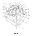
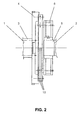
- the first exemplary embodiment shown in figures 1 and 2 illustrates a radially elastic coupling 10 for connecting two rotating machine parts 1 and 2.
- figure 2 shows for the first machine part 1 an engine shaft 3 with a flywheel 4.
- the second machine part 2 is formed by a torsionally flexible coupling 6, which is fitted on an output shaft 5.
- the radially elastic coupling 10 comprises four braces 11, each extending in the radial direction.
- the radially inner end portions 12 of the braces 11 are connected radially to one another at the centre Z of the coupling by means of a middle part 28.
- the radially elastic coupling 10 comprises two groups of two or more than two jibs 13 and 14 each.
- a connection to the rotating machine parts 1 and 2 is accomplished through the free end portions 16 and 17 of the jibs 13 and 14.
- four first jibs 13 and four second jibs 14 each are present, which results in a higher uniformity of the torque transmission.
- the jibs 13 and 14 each connect at one bound end portion 18 or 19 to radially outer end portions 15 of the braces 11, wherein at each brace 11, one jib 13 of the first group and one jib 14 of the second group are provided.
- the free end portions 16 of the first group of jibs 13 are connected to the first machine part 1
- the free end portions 17 of the second group of jibs 14 are formed for connection to the second rotating machine part 2.
- corresponding fastening openings 20 or 21 can be formed, so that the jibs 13 and 14 can be flanged onto the relevant machine parts 1 and 2 by means of bolts.
- All the braces 11 and jibs 13 and 14 are arranged in a common plane, so that a flat, plate-type component is obtained, which is made of one piece and usually will have a substantially constant thickness.
- the jibs 13 and 14 of a brace 11 are located on opposite sides of the brace and between each other include an angle of approximately 90 degrees.
- the jibs 13 and 14 of adjacent braces 11 are radially interlaced and proceed in parallel or at least substantially in parallel to one another, wherein in the present case, the first jibs 13 are disposed radially further outside than the jibs 14 of the second group.
- a radial intermediate space 22 is kept free, so that the jibs 13 and 14 do not contact each other in case of a deflection of the overall structure as a consequence of radial displacement between the machine parts 1 and 2.
- the radial deflection of the jibs 13 and 14 as well as the deflection of the braces 11 in the circumferential direction can be adjusted as required by means of longitudinal slits 23 and 24.
- the jibs 13 and 14 are able to deflect in the axial direction, i.e. vertically to the main plane of extent, i.e. the plane shown in Fig. 1 , of the coupling 10, as a result of which in addition to a radial compensation, an easy axial compensation is made possible.
- the radially inner jibs 14 each extend to an adjacent brace 11 and are spaced from it in the circumferential direction only by a small gap 27. Depending on the size of the coupling, the gap 27 has a width of 1 to 20 mm. Owing to the long jibs 14, high radial compensation by the coupling is possible.
- the jibs 13 located radially further outside extend similarly up to the height of an adjacent brace 11.
- a large free bending length of the braces 11 contributes to high radial compensation. This should be understood to be the distance between the branching of the jibs 13, 14 and a middle part 28 connecting the braces 11, as it is illustrated in figure 1 .
- the free bending length 1 of the braces 11 is greater than the radial width b of a jib 13 or 14. It is preferably at least twice the width b or a multiple thereof.
- the braces 11 can be thinner than the jibs 13, 14, i.e. the maximum width s of the braces 11 is less than b.
- the number of radial braces 11 can be varied upwards or downwards, wherein the jibs 13 or 14 with the braces 11 can also include angles different from the one shown in figure 1 .
- brace 11 can be provided for each jib 13 or 14. Furthermore, for each jib 13 or 14, a separate brace 11 can be provided.
- Figures 3 and 4 show another variation of the radially elastic coupling 10 in an alternative installation situation, in which the torsionally flexible coupling 6 is disposed on the engine side.
- the inner end portions 12 of the braces 11 are connected to one another by means of a middle part 28 that is formed as a ring 25.
- the ring 25 comprises a through-opening 26 in the center Z of the coupling.
- FIG. 5 shows an example of a variant of a radially elastic coupling 10 with five braces 11, which are connected radially to one another in the center Z.
- Each brace 11 in turn has a first jib 13 and a second jib 14, which include an angle of approximately 90 degrees between each other.
- the first jibs 13 are connected with their free ends to a first machine part and the second jibs 14 are connected with their free ends to a second machine part.
- the jibs 13 and 14 of directly adjacent braces 11 pointing to one another are radially interlaced, wherein a jib 13 and its associated brace 11 delimit a substantially triangular free space.
- a jib 14 of an adjacent brace 11 extends into this free space, so that the jibs 13 and 14 overlap if viewed in the radial direction.
- the jib 14, which is situated radially further inside, proceeds up to the adjacent brace 11 and in the circumferential direction, is only spaced by a gap 27 from it, so that it may have a great length.
Landscapes
- Engineering & Computer Science (AREA)
- General Engineering & Computer Science (AREA)
- Mechanical Engineering (AREA)
- Jib Cranes (AREA)
- Steering Controls (AREA)
- Tires In General (AREA)
- Springs (AREA)
- Peptides Or Proteins (AREA)
- Motor Power Transmission Devices (AREA)
- Mechanical Operated Clutches (AREA)
Applications Claiming Priority (1)
| Application Number | Priority Date | Filing Date | Title |
|---|---|---|---|
| DE102009005561 | 2009-01-20 |
Publications (2)
| Publication Number | Publication Date |
|---|---|
| EP2208904A2 true EP2208904A2 (fr) | 2010-07-21 |
| EP2208904A3 EP2208904A3 (fr) | 2012-05-02 |
Family
ID=42111863
Family Applications (1)
| Application Number | Title | Priority Date | Filing Date |
|---|---|---|---|
| EP10150751A Withdrawn EP2208904A3 (fr) | 2009-01-20 | 2010-01-14 | Couplage élastique radial |
Country Status (6)
| Country | Link |
|---|---|
| US (1) | US20100184520A1 (fr) |
| EP (1) | EP2208904A3 (fr) |
| JP (1) | JP2010169262A (fr) |
| KR (1) | KR20100085874A (fr) |
| CN (1) | CN103075435A (fr) |
| DE (1) | DE102010004773A1 (fr) |
Families Citing this family (6)
| Publication number | Priority date | Publication date | Assignee | Title |
|---|---|---|---|---|
| DE102012107020A1 (de) | 2012-08-01 | 2014-02-06 | Dr. Ing. H.C. F. Porsche Aktiengesellschaft | Radialelastische Wellenkupplung zur Drehmomentübertragung von einer Eingangswelle zu einer Ausgangswelle |
| GB2514386B (en) | 2013-05-22 | 2019-07-31 | Euroflex Trans Limited | Flexible shaft coupling |
| DE102013221430B4 (de) * | 2013-10-22 | 2024-09-19 | Deutsches Zentrum für Luft- und Raumfahrt e.V. | Axialkompensator zum Ausgleich von längs einer gemeinsamen Achse bewegbar angeordneten bzw. längenveränderbaren Komponenten |
| JP6174107B2 (ja) * | 2015-12-21 | 2017-08-02 | 上銀科技股▲分▼有限公司 | 駆動伝達装置 |
| EP4333267A1 (fr) | 2022-08-29 | 2024-03-06 | Walter Henrich GmbH | Arbre de rotor modulaire pourvu de canaux de refroidissement intégrés |
| JP2024110152A (ja) * | 2023-02-02 | 2024-08-15 | 三菱重工業株式会社 | 動力伝達継手 |
Citations (3)
| Publication number | Priority date | Publication date | Assignee | Title |
|---|---|---|---|---|
| DE1800613A1 (de) | 1968-02-26 | 1969-09-04 | Ringspann Maurer Kg A | Wellenkupplung |
| US3625024A (en) | 1969-05-29 | 1971-12-07 | Takefusa Kikuchi | Coupling |
| WO1991016550A1 (fr) | 1990-04-20 | 1991-10-31 | Zero-Max, Inc. | Accouplement articule servant a accoupler un element d'entrainement a un element entraine |
Family Cites Families (7)
| Publication number | Priority date | Publication date | Assignee | Title |
|---|---|---|---|---|
| US2630692A (en) * | 1948-05-04 | 1953-03-10 | Walter E Naugler | Flexible coupling |
| US3685314A (en) * | 1971-03-25 | 1972-08-22 | Kaman Aerospace Corp | Flexible universal joint |
| NL7400886A (nl) * | 1974-01-23 | 1975-07-25 | Philips Nv | Flexibele askoppeling. |
| US4321805A (en) * | 1979-06-01 | 1982-03-30 | Kaman Aerospace Corporation | Rotary drive flexible coupling |
| US5221232A (en) * | 1989-01-12 | 1993-06-22 | Zero-Max, Inc. | Flexible disc-like coupling element |
| WO1996012116A1 (fr) * | 1994-10-13 | 1996-04-25 | Klaus Ehrlenspiel | Accouplements d'arbres, en particulier accouplements compensateurs |
| FR2728636B1 (fr) * | 1994-12-21 | 1997-01-24 | Hispano Suiza Sa | Accouplement flexible pour arbres tournants |
-
2010
- 2010-01-06 JP JP2010001258A patent/JP2010169262A/ja active Pending
- 2010-01-14 DE DE102010004773A patent/DE102010004773A1/de not_active Withdrawn
- 2010-01-14 EP EP10150751A patent/EP2208904A3/fr not_active Withdrawn
- 2010-01-20 KR KR1020100005224A patent/KR20100085874A/ko not_active Ceased
- 2010-01-20 CN CN2010103004523A patent/CN103075435A/zh active Pending
- 2010-01-20 US US12/690,353 patent/US20100184520A1/en not_active Abandoned
Patent Citations (3)
| Publication number | Priority date | Publication date | Assignee | Title |
|---|---|---|---|---|
| DE1800613A1 (de) | 1968-02-26 | 1969-09-04 | Ringspann Maurer Kg A | Wellenkupplung |
| US3625024A (en) | 1969-05-29 | 1971-12-07 | Takefusa Kikuchi | Coupling |
| WO1991016550A1 (fr) | 1990-04-20 | 1991-10-31 | Zero-Max, Inc. | Accouplement articule servant a accoupler un element d'entrainement a un element entraine |
Also Published As
| Publication number | Publication date |
|---|---|
| JP2010169262A (ja) | 2010-08-05 |
| DE102010004773A1 (de) | 2010-07-22 |
| KR20100085874A (ko) | 2010-07-29 |
| US20100184520A1 (en) | 2010-07-22 |
| EP2208904A3 (fr) | 2012-05-02 |
| CN103075435A (zh) | 2013-05-01 |
Similar Documents
| Publication | Publication Date | Title |
|---|---|---|
| US20100184520A1 (en) | Radially elastic coupling | |
| US9523410B2 (en) | Planetary gear mechanism with adjustable ring gear | |
| US7651399B2 (en) | Torsional vibration damper | |
| US8162762B2 (en) | Generator flexible drive coupling | |
| JP2013061068A (ja) | 軸方向力ローディングのためのフレキシブルダイヤフラムカップリング | |
| US20090250301A1 (en) | Clutch unit | |
| CA2263230A1 (fr) | Accouplement flexible muni de colonnes courbes rentrantes permettant de maintenir une grande rigidite en torsion malgre des defauts d'alignement | |
| EP3374633B1 (fr) | Train d'entraînement d'éolienne et procédés avec couplage élastique | |
| CN121241207A (zh) | 空间弹性离合器以及离合器布置 | |
| US5700197A (en) | Flexible shaft coupling having a plurality of driving side leaf spring members, a plurality of driven side leaf spring members and one relay member | |
| US8579589B2 (en) | Mechanism for attenuating torque pulsations between an engine and a rotorcraft rotor driven by the engine | |
| EP2990676B1 (fr) | Couplage | |
| US20090098944A1 (en) | Disk for the transmission of a torque in a torque transmission device of a motor vehicle | |
| KR102234192B1 (ko) | 편심 및 편각 동시 보상이 가능한 디스크 커플링 | |
| EP0583505B1 (fr) | Accouplement d'arbres | |
| KR20210147386A (ko) | 8각 링크유닛을 구비한 커플링 장치 | |
| EP2999896B1 (fr) | Couplage d'arbre flexible | |
| EP3929078A1 (fr) | Hélicoptère | |
| US8317627B2 (en) | Intermediary flange, combined intermediary flange unit and vibration damper | |
| US10100878B2 (en) | Flexible coupling element | |
| CN114641631B (zh) | 驱动系统 | |
| KR102260609B1 (ko) | 축방향 변위 제한 플렉시블 커플링 | |
| JP2003521648A (ja) | 駆動ユニットからハイドロダイナミックコンバーターへのトルク伝達用の駆動ディスク | |
| US9512885B2 (en) | Coupling device, in particular for industrial applications | |
| JP2011094671A (ja) | 軸継ぎ手 |
Legal Events
| Date | Code | Title | Description |
|---|---|---|---|
| PUAI | Public reference made under article 153(3) epc to a published international application that has entered the european phase |
Free format text: ORIGINAL CODE: 0009012 |
|
| AK | Designated contracting states |
Kind code of ref document: A2 Designated state(s): AT BE BG CH CY CZ DE DK EE ES FI FR GB GR HR HU IE IS IT LI LT LU LV MC MK MT NL NO PL PT RO SE SI SK SM TR |
|
| AX | Request for extension of the european patent |
Extension state: AL BA RS |
|
| PUAL | Search report despatched |
Free format text: ORIGINAL CODE: 0009013 |
|
| AK | Designated contracting states |
Kind code of ref document: A3 Designated state(s): AT BE BG CH CY CZ DE DK EE ES FI FR GB GR HR HU IE IS IT LI LT LU LV MC MK MT NL NO PL PT RO SE SI SK SM TR |
|
| AX | Request for extension of the european patent |
Extension state: AL BA RS |
|
| RIC1 | Information provided on ipc code assigned before grant |
Ipc: F16D 3/79 20060101ALI20120323BHEP Ipc: F16D 3/62 20060101AFI20120323BHEP |
|
| STAA | Information on the status of an ep patent application or granted ep patent |
Free format text: STATUS: THE APPLICATION IS DEEMED TO BE WITHDRAWN |
|
| 18D | Application deemed to be withdrawn |
Effective date: 20121103 |